Installation Manual P/N MMI-20016185, Rev.
Safety and approval information This Micro Motion product complies with all applicable European directives when properly installed in accordance with the instructions in this manual. Refer to the EC declaration of conformity for directives that apply to this product. The EC declaration of conformity, with all applicable European directives, and the complete ATEX Installation Drawings and Instructions are available on the internet at www.micromotion.com/atex or through your local Micro Motion support center.
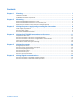
Contents Chapter 1 Planning ......................................................................................................... 1 Installation checklist ................................................................................................................. 1 9739 MVD transmitter components............................................................................................. 2 Chapter 2 Mounting.........................................................................................
Chapter 1 Planning Topics covered in this chapter: ♦ Installation checklist ♦ 9739 MVD transmitter components Installation checklist q Make sure that the transmitter is suitable for the environment in which it will be installed. See the hazardous area specified on the transmitter approval tag. q Locate and mount the transmitter according to the following requirements: − The transmitter must be accessible for service and calibration.
Planning Figure 1-1 Standard housing lockout clamp components (ATEX installations only) A B C D E F A Housing cover B Lip C Mounting screw D Clamp E Threaded hole F Housing base Notes • Before installing the transmitter housing lockout clamp, make sure that you have properly installed the transmitter and the flowmeter has been zeroed. 9739 MVD transmitter components Figure 1-2 shows the 9739 MVD transmitter components.
Planning Figure 1-2 Components of the 9739 MVD transmitter A I B C D H E F G A Removable housing cover B Electronics module C Intrinsically safe sensor wiring terminals D Non–intrinsically-safe output wiring terminals E Conduit opening for sensor wiring F Conduit opening for power supply wiring G Conduit opening for output wiring H Housing base I User interface: with or without display options Installation Manual 3
Chapter 2 Mounting Topics covered in this chapter: ♦ Mount the 9739 MVD transmitter to a wall ♦ Mount the 9739 MVD transmitter to an instrument pole ♦ Rotate the user interface on the electronics module (optional) Mount the 9739 MVD transmitter to a wall Prerequisites • Use four 5/16-inch diameter (or M8) bolts and nuts that can withstand the process environment. Micro Motion does not supply bolts or nuts (appropriate bolts and nuts are available as an option).
Mounting Figure 2-1 Transmitter mounting dimensions (front and side views) A D E C B F A 2.81 inches (71 mm) B 7.31 inches (186 mm) C 4.51 inches (115 mm) D 8.39 inches (213 mm) E 9.19 inches (233 mm) F Figure 2-2 With display: 6.82 inches (173 mm); Without display: 7.28 inches (185 mm) Transmitter mounting dimensions (bottom view) E D A B C A 0.19 inches (5 mm) B 2.38 inches (60 mm) C 2.38 inches (60 mm) D 1.53 inches (39 mm) E With display: 10.46 inches (266 mm); Without display: 11.
Mounting Mount the 9739 MVD transmitter to an instrument pole Prerequisites • Use two 5/16-inch U-bolts for 2-inch pipe, and four matching nuts, that can withstand the process environment. Micro Motion does not supply U-bolts or nuts. • Ensure the instrument pole extends at least 12 inches (305 mm) from a rigid base, and is no more than 2 inches (50.8 mm) in diameter. Procedure Mount the transmitter to an instrument pole, using Figure 2-3 as a guide.
Mounting Rotate the user interface on the electronics module (optional) The user interface on the transmitter electronics module can be rotated 180° from the original position. Procedure 1. Shut off power to the unit. 2. Unscrew and remove the transmitter housing cover. If the transmitter is installed in a hazardous area, be sure you have shut off power to the transmitter before removing the housing cover.
Chapter 3 Wiring the power supply and grounding the transmitter Topics covered in this chapter: ♦ Power supply requirements ♦ Wire the power supply ♦ Ground the 9739 MVD transmitter Power supply requirements The 9739 MVD transmitter can accept either AC or DC power. The transmitter automatically recognizes the source voltage. Table 3-1 lists the AC and DC power requirements for the 9739 MVD transmitter.
Wiring the power supply and grounding the transmitter Figure 3-1 Power supply wiring terminals A B E C D A External ground terminal B Power supply conduit opening C L / L1 for AC; + for DC D N / L2 for AC; – for DC E Power ground terminal 5. Secure the input power connections at the two labeled terminals. For AC-powered transmitters, you may install a switch in the power supply line.
Wiring the power supply and grounding the transmitter Important Follow the plant standards if a separate high-integrity intrinsically safe ground scheme is used. If national standards or plant standards are not in effect, adhere to the following guidelines for grounding: • Use copper wire, 14 AWG (2.5 mm2) or larger wire size. • Keep all ground leads as short as possible, less than 1 Ω impedance. • You can use the internal power ground terminal or the external ground terminal to ground the transmitter.
Chapter 4 Wiring the 9739 MVD transmitter to the sensor Topics covered in this chapter: ♦ Prepare the 9-wire cable ♦ Wire the transmitter to the sensor using jacketed cable ♦ Wire the transmitter to the sensor using shielded or armored cable ♦ Sensor and transmitter terminals ♦ Micro Motion 9-wire cable types and usage Prepare the 9-wire cable The type of cable you are using to install the 9739 MVD transmitter determines how you prepare the 9-wire cable.
Wiring the 9739 MVD transmitter to the sensor Figure 4-1 12 Preparing jacketed cable Micro Motion 9739 MVD Transmitters
Wiring the 9739 MVD transmitter to the sensor Figure 4-2 Preparing shielded or armored cable Installation Manual 13
Wiring the 9739 MVD transmitter to the sensor Wire the transmitter to the sensor using jacketed cable Prerequisites For ATEX installations, the jacketed cable must be installed inside a user-supplied sealed metallic conduit that provides 360° termination shielding for the enclosed cable. Sensor wiring is intrinsically safe. To keep sensor wiring intrinsically safe, keep the sensor wiring separated from power supply wiring and output wiring.
Wiring the 9739 MVD transmitter to the sensor Table 4-2 Sensor and transmitter terminal designations Wire color Sensor terminal Transmitter terminal Function Black No connection 0 Drain wires Brown 1 1 Drive + Red 2 2 Drive − Orange 3 3 Temperature − Yellow 4 4 Temperature return Green 5 5 Left pickoff + Blue 6 6 Right pickoff + Violet 7 7 Temperature + Gray 8 8 Right pickoff − White 9 9 Left pickoff − e. Tighten the screws to hold the wire in place. f.
Wiring the 9739 MVD transmitter to the sensor Figure 4-3 Cable gland and cable (exploded view) B A C F D E G H I A Cable B Sealing nut C Compression nut D Brass compression ring E Braided shield F Cable G Tape or heat-shrink tubing H Clamp seat (shown as integral to nipple) I 16 Nipple 3. Unscrew the nipple from the compression nut. 4. Screw the nipple into the conduit opening for the 9-wire cable. Tighten it to one turn past hand-tight. 5.
Wiring the 9739 MVD transmitter to the sensor Figure 4-4 Cross-section of assembled cable gland with cable A B D C G A E F A Cable B Sealing nut C Seal D Compression nut E Braided shield F Brass compression ring G Nipple 10. Remove the junction-box cover or transmitter housing cover. 11. At both the sensor and transmitter, connect the cable according to the following procedure: a.
Wiring the 9739 MVD transmitter to the sensor Table 4-3 Sensor and transmitter terminal designations continued Wire color Sensor terminal Transmitter terminal Function Violet 7 7 Temperature + Gray 8 8 Right pickoff − White 9 9 Left pickoff − b. Tighten the screws to hold the wires in place. c. Ensure integrity of gaskets, grease all O-rings, then replace the junction-box and transmitter housing covers and tighten all screws, as required.
Wiring the 9739 MVD transmitter to the sensor Figure 4-6 F-Series, Model D, and Model DL sensor terminals Figure 4-7 Model DT sensor terminals (user-supplied metal junction box with terminal block) 1 2 3 4 5 6 7 8 9 A A Earth ground Figure 4-8 9739 MVD transmitter terminals Installation Manual 19
Wiring the 9739 MVD transmitter to the sensor Micro Motion 9-wire cable types and usage Cable types Micro Motion supplies three types of 9-wire cable: jacketed, shielded, and armored. Note the following differences between the cable types: • Armored cable provides mechanical protection for the cable wires. • Jacketed cable has a smaller bend radius than shielded or armored cable. • If ATEX compliance is required, the different cable types have different installation requirements.
Wiring the 9739 MVD transmitter to the sensor Table 4-6 Bend radii of shielded cable Jacket material Outside diameter Minimum bend radii Static (no load) condition Under dynamic load PVC 0.2 inches (14 mm) 4–1/4 inches (108 mm) 8–1/2 inches (216 mm) Teflon FEP 0.425 inches (11 mm) 3–1/4 inches (83 mm) 6–3/8 inches (162 mm) Table 4-7 Bend radii of armored cable Jacket material Outside diameter Minimum bend radii Static (no load) condition Under dynamic load PVC 0.
Wiring the 9739 MVD transmitter to the sensor Figure 4-10 Cross-section view of shielded cable A B C (1) D E (4) G (5) F (4) A Outer jacket B Tin-plated copper braided shield C Foil shield (1 total) D Inner jacket E Drain wire (4 total) F Foil shield (4 total) G Filler (5 total) 22 Micro Motion 9739 MVD Transmitters
Wiring the 9739 MVD transmitter to the sensor Figure 4-11 Cross-section view of armored cable A B C (1) D E (4) G (5) F (4) A Outer jacket B Stainless steel braided shield C Foil shield (1 total) D Inner jacket E Drain wire (4 total) F Foil shield (4 total) G Filler (5 total) Installation Manual 23
Chapter 5 Wiring the outputs Topics covered in this chapter: ♦ Analog output terminals ♦ Wire the primary and secondary mA outputs ♦ Wire the frequency/pulse output ♦ Wire the discrete output ♦ Wire the discrete input ♦ Wire to a pressure transmitter Analog output terminals Use the upper and lower terminal blocks on the right side of the partition on the 9739 MVD transmitter electronics module for analog output wiring connections. Use twisted-pair, shielded cable for all I/O connections.
Wiring the outputs Figure 5-1 Analog output terminals Table 5-8 Analog output wiring terminal designations Terminal Function 14 Frequency output, DC supply voltage (+) 15 and 16 Frequency/pulse output (+) 16 Return 17 Primary variable (PV+) mA output 18 Primary variable (PV–) mA output 19 Secondary variable (SV+) mA output 20 Secondary variable (SV–) mA output 21 and 16 Discrete input (Zero) (+) 22 and 16 Discrete output (Control output) 23 Signal ground 24 and 23 Temperature out
Wiring the outputs Wire the primary and secondary mA outputs Use terminals 17 and 18 for the primary mA output. Use terminals 19 and 20 for the secondary mA output. The mA outputs produce a user-selected 0–20 mA or 4–20 mA current. When configured as 4–20 mA outputs, the mA outputs can supply loop-powered process indicators. The primary mA output can also be configured for HART®/Bell 202 communications. Procedure 1.
Wiring the outputs Figure 5-3 Wiring the primary mA output for HART communications A R1 PV+ 17 B PV- R3 R2 C 18 A HART communications tool, ProLink II, or AMS modem B Communicator loops or PV (Primary Variable) terminals C DCS or PLC with internal resistor Notes • If necessary, add resistance in the loop by installing a resistor R1. SMART FAMILY® devices require a minimum loop resistance of 250 Ω. Loop resistance must not exceed 1000 Ω, regardless of the communication setup.
Wiring the outputs Figure 5-4 Wiring the frequency/pulse output A C B A FREQ+ B RETURN C PLC or pulse counter • To configure the output for increased current, add a 1 to 3 kΩ resistor across terminals 14 and 15 (see Figure 5-5).
Wiring the outputs Figure 5-6 Wiring the frequency/pulse output for constant current A D C B A FREQ+ B RETURN C 100 to 250 Ω resistor D PLC or pulse counter • To wire the output to use external power, see Figure 5-7. For recommended resistor versus supply voltage, see Figure 5-8. Do not exceed 30 VDC input. Excessive current will damage the transmitter. Terminal current must be less than 500 mA.
Wiring the outputs Figure 5-7 Wiring the frequency/pulse output for external power A E B C D A FREQ+ B RETURN C A pull-up resistor, which must be of sufficient value to limit loop current to less than 500 mA depending on the total loop resistance at the transmitter D 3 to 30 VDC power supply E PLC or pulse counter Figure 5-8 30 Recommended pull-up resistor versus supply voltage (external power) Micro Motion 9739 MVD Transmitters
Wiring the outputs Wire the discrete output The discrete output can indicate the flow direction, transmitter zeroing in progress, pressure input failure, faults, event 1 or event 2. You can wire the discrete output to use internal or external power. See Micro Motion 9739 MVD Transmitters: Configuration and Use Manual for more information on configuring the discrete output for events. Procedure Use terminals 22 and 16 for the discrete output.
Wiring the outputs Figure 5-10 Wiring the discrete output for external power A B A A pull-up resistor, which must be of sufficient value to limit loop current to less than 500 mA depending on total loop resistance at the transmitter B 3 to 30 VDC power supply Figure 5-11 Recommended pull-up resistor versus supply voltage (external power) Wire the discrete input Procedure Use terminals 21 and 16 for the discrete input. See Figure 5-12 for wiring the discrete input.
Wiring the outputs Figure 5-12 Wiring the discrete input A - + A Remote switch Wire to a pressure transmitter The 9739 MVD transmitter accepts inputs from a pressure transmitter for pressure compensation. Because the pressure transmitter wiring is not intrinsically safe, keep the pressure transmitter wiring separated from the power supply wiring, intrinsically safe sensor wiring, and any other intrinsically safe wiring.
Wiring the outputs • If the pressure transmitter requires a power supply greater than 13.6 V, or if other loop devices are required, you can use an external source to power the pressure transmitter. Use terminals S and 23 (see Figure 5-14).
Wiring the outputs Figure 5-15 Wiring to a pressure transmitter — digital communications A B C 24 VDC D A Pressure transmitter, with HART only B 250 Ω ±5 %, 0.5 W C 250 Ω ±5 %, 0.
Chapter 6 Wiring digital communications Topics covered in this chapter: ♦ Wire the transmitter to an RS-485 multidrop network ♦ Wire the transmitter to a Bell 202 multidrop network Wire the transmitter to an RS-485 multidrop network Prerequisites Use twisted-pair, shielded cable that consists of 24 AWG (0.25 mm2) or larger wire between the 9739 MVD transmitter and the RS-485 communication device. Maximum cable length is 4000 ft (1200 m).
Wiring digital communications Choose from the following options for wiring the RS-485 network: • To connect one transmitter to a host controller for the RS-485 serial communication, see Figure 6-1. Figure 6-1 Wiring a 9739 MVD transmitter to a host controller RS-485 A 26 B 27 9739 • To connect multiple transmitters to a host controller for the RS-485 serial communication, see Figure 6-2.
Wiring digital communications Figure 6-3 Wiring to a typical HART® network 9739 9739 A PV+ 17 PV+ CN2Z30 PV– 18 PV– CN2D30 B E E F 4-20 mA 4-20 mA C D 24 VDC A HART communications tool, ProLink II, or AMS modem B 250 Ω load C IFT9701 D R-Series E SMART FAMILY® transmitter F DC source required for other HART 4–20 mA passive transmitters Notes • SMART FAMILY devices require a minimum loop resistance of 250 Ω. Loop resistance must not exceed 1000 Ω.
© 2010, Micro Motion, Inc. All rights reserved. P/N MMI-20016185, Rev. AA *MMI-20016185* For the latest Micro Motion product specifications, view the PRODUCTS section of our web site at www.micromotion.com Micro Motion Inc.