Instruction & maintenance leaflet IP2046IM, Rev. AA November 2006 MSP400RH Mobrey MSP400RH Series Level Transmitter www.mobrey.
CONTENTS Page 1. Introduction 3 2. 2.1 2.2 2.3 The MSP400RH ultrasonic level transmitter Type numbering system Pressure Equipment Directive Specifications 3 3 4 4 3. 3.1 3.1.1 3.1.2 3.1.3 3.1.4 3.2 3.3 3.4 Installation Location of the MSP400RH transmitter General considerations Liquid surface conditions In-tank / well effects Open Channel Flow installations Mounting the transmitter above the liquid surface Wiring Additional components in the 2 wire loop 6 6 6 7 8 8 10 11 12 4. 4.1 4.2 4.3 4.4 4.
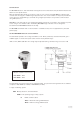
1.0 Introduction The MSP400 ultrasonic level transmitter is designed to be mounted above a liquid and will measure the distance to the liquid surface. When programmed with details of the vessel, sump or open channel, the MSP400 will compute level, contents or flow and give a 4-20mA signal proportional to the chosen variable. 2 relays are provided for control functions. Programming is achieved using integral push buttons or by remote communication using HART protocol.
2.2 Pressure Equipment Directive The MSP400RH transmitter does not fall within the PED definition as enclosing a pressurised fluid, so is therefore outside the scope of the Directive. Accordingly, the Declaration of Conformity does not list the Pressure Equipment Directive. 2.
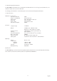
-40 / +158°F Ø 144 (5.7") -40 / +70°C IP66 / IP67 Ambient 2 x M20 conduit connections 1 x cable gland 1 x blanking plug 135 (5.3") 60mm A/F (2.4") 65 (2.6") MSP400RH-B28 : 2" BSPT MSP400RH-N28 : 2" NPT -30 / +70°C -22 / +158°F -0,25 / +3,0bar -4 / +44psi MIN : 0.45m (18”) MAX : 11.0m (433”) Wetside b.
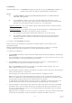
3.0 Installation Important safety notice : The MSP400 is designed for safe area use only, and must not be installed in a hazardous area, even if the power is supplied through a barrier device. General a. b. Installation must be carried out by suitably trained personnel in accordance with the applicable code of practice.
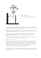
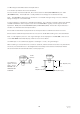
Max 3° (1.3"/ft) i.e. 0,11m/m C D Min = 0.45m (18”) D Max = 11m (433”) C = 0.3m (12”) min to 0.88m (36”) D • If the transmitter is mounted in an enclosed tank, avoid mounting the transmitter in the centre of the tank roof as this could act as a parabolic reflector and create unwanted echoes. Avoid applications where heavy condensation could form on the transducer face.
3.1.3 In-tank effects • Stirrers or agitators can cause a vortex. Always try to mount the transmitter off-centre of any vortex to maximise the return echo. As stirrer blades become uncovered they will create echoes as they pass through the ultrasonic beam. The transmitter can be tuned to ignore these false echoes on site. • In non-linear tanks with rounded or conical bottoms, always mount the transmitter off-centre.
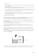
Transmitter front face Flow Channel invert Primary device (eg. flume, weir) invert In addition to the above, when setting the bottom reference on a ‘V’ notch weir it is important that the true invert of the weir is taken and not the meniscus liquid level, which may be 3 to 4mm (1/8”) above the true invert. Transmitter bottom reference Meniscus True invert • The liquid surface at the point of measurement must have a stable, smooth surface and uniform approach velocity.
3.2 Mounting the transmitter above the liquid surface. A 2” thread is provided to mount the transmitter. The user should check the thread form, which will be either 2” BSPT (MSP400RH-B28) or 2” NPT (MSP400RH-N28). The thread form is clearly marked on the hexagon of the transducer body. Note : The MSP400 is designed to be mounted in a non-metallic fitting or flange. The use of metallic fittings or flanges is not recommended. To help installation, a bracket kit is available from Mobrey.
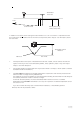
3.3 Wiring The transmitter is supplied with cable gland suitable for cable sizes 4-8mm diameter. Terminal 1 2 3 4 5 6 7 8 : : : : : : : : +24V dc 0v dc RL1 (SPST) RL1 (SPST) RL2 (SPST) RL2 (SPST) MSP-RTP temperature probe (if used) MSP-RTP temperature probe (if used) Earth Screen : Connect to a standard earth in the control room. Max 3000m (9845ft) Earth screen in control room only Twisted pair, screened Min 0,22mm2 (25 SWG / 24 AWG) Max 1,5mm2 (17 SWG / 15 AWG) Ø 4 - 8mm (0.15 - 0.
3.3.3 Relays The MSP400RH transmitter has 2 integral relays which may be used for control purposes. These relays are light duty and should be used as signal relays only, with control functions being performed by external control relays. Relay 2 is defaulted as a ‘fault’ relay, normally energised, but may be reconfigured on site as a set point relay if required. 3.4 Additional components in the two wire loop. 3.4.
4.0 Commissioning, programming and operation The MSP400 operates from a menu of parameters, each held in a specific memory location within the instrument. The memory locations may be pictured as a matrix, and the user navigates to each parameter to programme the instrument using ↓ and → steps.
4.2 Power up On power up, the MSP400 will take a few seconds to initialise. The display will run through a set-up routine, first illuminating all display characters then showing the software revision number. Once checks are complete, the display will show the Primary Variable (PV) determined based upon the factory default values in the memory. On a new instrument aimed at a good target, this will be what the MSP400 calculates as a level reading based upon the default value for the bottom reference.
4.4 Setting up for the chosen application - the Main Menu. Refer now to the main menu structure chart in Appendix A. It is important to note that MSP400 programming is most easily accomplished by first selecting the duty the transmitter is to perform. Once a duty is selected (see section 4.4.1), a “mini-wizard” programming assistant is invoked and the user is thereafter only asked for information relevant to the duty chosen.
4.4.2 Selecting the units of measurement Screen display: Factory default setting: MSP400RH-B28 MSP400RH-N28 unitS m ft i) Note that the factory default units of measurement are dictated by the model type, which may be Imperial (ft) or Metric (m). The user can reconfigure a Metric unit to be an Imperial or vice-versa by changing the base units (b.unit) of the MSP400 - refer to section 4.7.
4.4.3 Setting the correct bottom reference Screen display: Factory default value: MSP400RH-B28 MSP400RH-N28 b.rEF 11 36 The MSP400 leaves the factory with the bottom reference pre-programmed to the maximum range of the instrument, either 11m or 36ft. 20/4 ullage b.rEF 4/20 liquid level To change the bottom reference: a) Press the green button ↓ to display the current “b.rEF” menu entry screen. b) Press the blue button → to enter the “b.rEF” menu and to display the current bottom reference in use.
4.4.4 Selecting the correct Profile algorithm. Screen display: Factory default value: ProF Linear This selection is offered only if the user has chosen a duty of Flow or Contents, or is shown when manually navigating the main menu - ignore if duty chosen is Level or Distance. The MSP400 is pre-programmed with a selection of popular profiles which are mathematical formulae to convert a linear level reading to a flow or volumetric PV.
Note: The complete range of options is displayed, regardless of the duty selected earlier. e) Once the desired profile is shown (flashing) on the display, press the blue button → to select this option. It will now stop flashing. f) If the chosen profile is incorrect, the edit sequence for the profile selection can be re-started by pressing the blue button → again. If the profile is correct, press the red button ↵ to save the profile to memory and automatically scroll on to the next main menu option.
If the profile chosen is any other contents profile, press the red button ↵ to save the profile to memory and automatically scroll on to the next main menu option “Cont @ max”, Refer to Section 4.4.9. 4.4.5 Power factor for the chosen flow law. Screen display: Factory default value: P.FACt 1.
To edit the scale factor a) Press the blue button → to enter the “SCALE” menu and to display the current scale factor in use. If this is correct, press the red button ↵ return to the main menu. If the scale factor is to be edited, press the blue button → again to allow editing The leading digit of the current scale factor will now be flashing, indicating it may be changed. b) Use the green button ↓ to edit the value of the leading digit.
4.4.8 Maximum flow entry Screen display Factory default value Flo @ max 1.000 This selection is offered only if the user has chosen a duty of Flow which requires entry of the maximum flow capability of the chosen structure (not the maximum flow expected in the application), or is shown when manually navigating the main menu - ignore if duty chosen is Level, Distance or Contents.
4.4.10 Setting the 4mA point Screen Display: Factory default value: 4 0.000 Enter the value of the PV which you require to be signalled by 4mA The 4mA point may be set above or below the 20mA point to suit the monitoring or control equipment.
4.4.12 Setting the damping applied to the output Screen display Factory default value d 3 The damping value entered is actually a time constant in seconds which is applied as smoothing to the displayed PV and current output. A new value may be entered up to a maximum value of 9999 seconds. A large value will have the effect of smoothing out rapid changes of current output and will also smooth out the effects of turbulence and ripples on the liquid surface.
To change the output current action on alarm condition: a) Press the blue button → to enter the alarm action menu and to display the current selection. If this is correct, press the green button ↓ return to the main menu. b) If the action is to be changed, press the blue button → again to allow editing c) Press the green button ↓ to scroll through the list of available profile options, as given in the table above.
4.4.15 Setting the 4 and 20mA levels using actual liquid levels in the tank Screen display (SEt 4 & SEt 20) Factory default value Hold If you have already programmed the 4 and 20mA levels as above, you do not need to enter this menu. All the programming is now complete and you should press the red button ↵ to exit the programming menu and return to the main PV display.
4.5 Diagnostic data. See also Appendix A2. The MSP400 can display useful diagnostic data which can aid setting up and fault finding. To aid interpretation of the data presented, the data will alternate with suitable text to remind the user what data is being displayed. The user is not able to change or edit any of the data shown in the diagnostic section of the menu. To enter the diagnostic menu, the user should press the blue button → from the main display screen to display the text “diAg”.
4.6 Loop Test : See also Appendix A3 “tESt” The MSP400 has the facility to cycle through it’s programmed operating range without any change in the liquid level, causing the current output and relays to cycle through their normal operation. Also, the MSP400 can be programmed to fix the loop current at any desired value between 4 and 20mA to allow testing of any other loop or control instruments.
4.7 Engineering Set-up menu : See also Appendix A4 “Eng” The proficient user is able to fine tune operation of the MSP400 if site or application conditions are unusual. Users are recommended to leave all operational fine tuning parameters at the factory default settings unless they have a good understanding of the function and capability of the parameters.
4.7.2 Setting the Lost Echo Time Screen display Factory default value “LE” 900 The lost echo time is the time in seconds which the MSP400 will wait before taking the lost echo action as described in 4.4.13. A new value may be entered in the range 0 to 9999. It is recommended that the lost echo time be left at 900 seconds to avoid false trips and alarms due to temporary loss of echo due to transient poor surface conditions.
To edit the dead band: a) Press the blue button → to enter the dead band menu and to display the current value in use. If this is correct, press the red button ↵ return to the main menu. If the dead band is to be edited, press the blue button → again to allow editing The leading digit of the dead band value will now be flashing, indicating it may be changed. b) Use the green button ↓ to edit the value of the leading digit.
4.7.5 Setting the Pulse repetition frequency Screen display Factory default value: “Prf” 1.0 The rate of pulses transmitted by the MSP400 is set at a factory default value of once per second. The MSP400 may be set to transmit faster or more slowly at selected repetition rates between 0.5 and 2.0 times per second. The pulse repetition frequency may be changed to overcome cross talk problems if more than one ultrasonic transmitter is mounted in the same tank.
4.7.7 Setting the Spike rejection Screen display Factory default value: “SPi” 0 (disabled) In applications with high levels of acoustic or electrical noise, a spike could incorrectly trigger the echo detection system. In such cases, the value of SPi can be increased (in the range 0-100) which has the effect of rejecting such spikes. The user may have to try several different values to determine the best option.
If the new temperature is incorrect, the edit sequence can be re-started by pressing the blue button → again. If the temperature is correct, press the red button ↵ to save the new value to memory and automatically scroll on to the next main menu option: The next option will be “t.CAL” if the MSP400 is using the Mobrey remote temperature probe MSP-RTP to monitor the air temperature. If no external temperature probe is connected the next menu option will be “Ld.dEF”. Refer now to Section 4.7.10. 4.7.
To load factory default values: a) Press the blue button → to enter the load defaults menu and display “Ld.dEF” b) Press the blue button → for at least two seconds to flash the screen message “SurE”. c) Press the blue button → again to acknowledge the message and stop the message flashing. The user can now abort by pressing the blue button → again to return to the start of the menu, allowing moving on to “b.unit” (refer to section 4.7.11) or may continue on and load factory defaults.
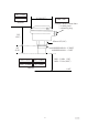
APPENDIX A1 MAIN MENU : PROGRAMMING PV PB1 duty PB1 PB2 Diagnostics PB2 for 2 sec Loop Test PB2&3 for 2 sec PB2 Eng Setup PV PB3 PB3 PB2 PB3 Display Duty PB2 Scroll through distance/level/ contents/flow PB2 Selected Duty PB2 duty PB3 to save unitS PB1 PB2 PB3 Display Units PB2 Scroll through options for chosen duty PB2 Selected Units PB2 unitS PB3 to save PB2 b.rEF PB1 PB3 Display Bottom Ref. PB2 Edit Bottom Ref. PB2 Display Bottom Ref. PB2 b.
APPENDIX A1 Cont’d / ... PB2 r1. On PB1 PB3 Display RL1 On Pt PB2 Edit RL1 On Pt PB2 Display RL1 On Pt PB2 r1. On PB3 to save PB2 r1.OFF PB3 Display RL1 Off Pt PB2 Edit RL1 Off Pt PB2 Display RL1 Off Pt PB2 PB1 r1.OFF PB3 to save PB2 r2. On PB1 PB3 Display RL2 On Pt PB2 Edit RL2 On Pt PB2 Display RL2 On Pt PB2 r2. On PB3 to save PB2 r2.OFF PB3 PB1 Display RL2 Off Pt PB2 Edit RL2 Off Pt PB2 Display RL2 Off Pt PB2 r2.
APPENDIX A2 DIAGNOSTICS MENU PV PB2 Diagnostics PB2 for 2 sec Loop Test PB3 PB2&3 for 2 sec Eng Setup PB2 PV PB3 PB3 PB3 PB1 Distance (diSt) PB1 • • Level (LEUEL) PB1 Display of the value of the diagnostic parameter is preceded by display of the parameter name (then flash for 1 second every 5 seconds) Pressing PB3 from any diagnostic parameter returns the display to the Diagnostics screen. Echo Size (Echo) PB1 No of Echoes (Echo.
APPENDIX A3 COMMISSIONING / LOOP TEST MENU PB2 PV PB3 PB2 for 2 second Diagnostics (diAg) Loop Test (tESt) PB2&3 for 2 sec Eng Setup (Eng) PB2 PV PB1 PB3 PB1 PB2 CyCLE PB1 PB3 PB2 LOOP PB1 PB3 Recall Fixed Current PB2 Set Distance =Bottom Ref PB2 Edit desired current value PB2 Toggle Ramping On/Off Display & output desired value PB2 CyCLE PB2 LOOP Loop Test 39 IP2046/IM Nov 2006
APPENDIX A4 ENGINEERING MENU PB2 PV PB2 for 2 sec Diagnostics Loop Test PB2&3 for 2 sec PB3 PB2 PB1 PB3 PB1 PB2 Display Threshold PB2 Display Threshold PB2 t.HoLd PB3 to save PB2 LE Display Threshold PV PB1 PB3 t.
APPENDIX B DEFAULT VALUE LISTING : MAIN MENU PARAMETERS Default value shown are for the metric model MSP400RH-B28. Where different, values for the imperial model MSP400RH-N28 are shown in brackets.
DEFAULT VALUE LISTING : ENGINEERING PARAMETERS Default value shown are for the metric model MSP400RH-B28. Where different, values for the imperial model MSP400RH-N28 are shown in brackets. PB2 PV Diagnostics PB2 for 2 sec Loop Test PB2&3 for 2 sec Eng Setup PB2 PB1 PB3 PB1 Display Threshold PB2 Site Settings PV PB1 Display Threshold PB2 Display Threshold PB2 t.HoLd Auto PB3 to save PB2 LE PB2 PB3 PB3 t.
APPENDIX C LISTING OF NON-LINEAR PROFILES IN THE MSP400 Screen Display Lin SPEC.P H. CYL.F SPH. H. CYL.D 3/2 5/2 a nnann SPEC.C Description Linear Special (plotted) Horiz. Cyl. (Flat) Spherical Horiz. Cyl.
APPENDIX D HART COMMUNICATIONS WITH THE MSP400 D 1.0 Overview The MSP400 ultrasonic level transmitter supports HART communications, which may be used to programme or interrogate the transmitter remotely from any point on the 2 wire loop. Any HART compatible communication device may be connected across the loop and, if loaded with the Device Description (DD) of the MSP400 transmitter, will have full access to the all of the parameters of the instrument as shown in D 3.
D 3.
IP2046/IM Nov 2006
IP2046/IM Nov 2006
Instruction & maintenance leaflet IP2046IM, Rev. AA November 2006 MSP400RH The Emerson logo is a trade mark and service mark of Emerson Electric Co. Rosemount is a registered trademark of Rosemount Inc. Mobrey is a registered trademark of Mobrey Ltd. All other marks are the property of their respective owners. We reserve the right to modify or improve the designs or specifications of product and services at any time without notice. © 2006 Mobrey Ltd. All rights reserved.