Configuration and Use Manual MMI-20021712, Rev AB April 2013 Micro Motion® Model 1700 Transmitters with Analog Outputs Includes the Chinese-Language Display Option
Safety messages Safety messages are provided throughout this manual to protect personnel and equipment. Read each safety message carefully before proceeding to the next step. Micro Motion customer service Email • Worldwide: flow.support@emerson.com • Asia-Pacific: APflow.support@emerson.com North and South America Europe and Middle East Asia Pacific United States 800-522-6277 U.K.
Contents Contents Part I Getting Started Chapter 1 Before you begin ............................................................................................................2 1.1 1.2 1.3 1.4 Chapter 2 About this manual ....................................................................................................................... 2 Transmitter model code ..............................................................................................................
Contents 6.4 6.5 6.6 Chapter 7 Configure the discrete output ................................................................................................... 93 Configure events ....................................................................................................................... 99 Configure digital communications .......................................................................................... 102 Completing the configuration ...............................................
Contents 10.22 10.23 10.24 10.25 10.26 10.27 10.28 10.29 10.30 Check Frequency Output Fault Action .............................................................................................206 Check Flow Direction .................................................................................................................. 206 Check the cutoffs ....................................................................................................................
Contents iv Micro Motion® Model 1700 Transmitters with Analog Outputs
Getting Started Part I Getting Started Chapters covered in this part: • • Before you begin Quick start Configuration and Use Manual 1
Before you begin 1 Before you begin Topics covered in this chapter: • • • • 1.1 About this manual Transmitter model code Communications tools and protocols Additional documentation and resources About this manual This manual provides information to help you configure, commission, use, maintain, and troubleshoot the Micro Motion transmitter.
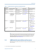
Before you begin Table 1-1: Communications tools, protocols, and related information Communications tool Supported protocols Scope In this manual For more information Display (standard) Not applicable Basic configuration and commissioning Complete user informa- Not applicable tion. See Appendix A. Chinese-language display Not applicable Basic configuration and commissioning Complete user informa- Not applicable tion. See Appendix B.
Before you begin Table 1-2: Additional documentation and resources Topic Document Sensor Sensor documentation Transmitter installation Hazardous area installation See the approval documentation shipped with the transmitter, or download the appropriate documentation from the Micro Motion web site at www.micromotion.com. All documentation resources are available on the Micro Motion web site at www.micromotion.com or on the Micro Motion user documentation CD.
Quick start 2 Quick start Topics covered in this chapter: 2.1 • • • • Power up the transmitter Check flowmeter status Make a startup connection to the transmitter Characterize the flowmeter (if required) • • Verify mass flow measurement Verify the zero Power up the transmitter The transmitter must be powered up for all configuration and commissioning tasks, or for process measurement. 1. Ensure that all transmitter and sensor covers and seals are closed.
Quick start 1. Wait approximately 10 seconds for the power-up sequence to complete. Immediately after power-up, the transmitter runs through diagnostic routines and checks for error conditions. During the power-up sequence, Alarm A009 is active. This alarm should clear automatically when the power-up sequence is complete. 2. Check the status LED on the transmitter. Table 2-1: Transmitter status reported by status LED LED state Description Recommendation Green No alarms are active.
Quick start 2.3 Make a startup connection to the transmitter For all configuration tools except the display, you must have an active connection to the transmitter to configure the transmitter. Follow this procedure to make your first connection to the transmitter. Identify the connection type to use, and follow the instructions for that connection type in the appropriate appendix. Use the default communications parameters shown in the appendix.
Quick start 2.
Quick start 2.4.
Quick start Figure 2-3: Tag on older straight-tube sensor (T-Series) Figure 2-4: Tag on newer straight-tube sensor (T-Series) 2.4.2 Flow calibration parameters (FCF, FT) Two separate values are used to describe flow calibration: a 6-character FCF value and a 4character FT value. They are provided on the sensor tag. Both values contain decimal points. During characterization, these may be entered as two values or as a single 10-character string. The 10-character string is called either Flowcal or FCF.
Quick start Example: Concatenating FCF and FT FCF = x.xxxx FT = y.yy Flow calibration parameter: x.xxxxy.yy Example: Splitting the concatenated Flowcal or FCF value Flow calibration parameter: x.xxxxy.yy FCF = x.xxxx FT = y.yy 2.4.3 Density calibration parameters (D1, D2, K1, K2, FD, DT, TC) Density calibration parameters are typically on the sensor tag and the calibration certificate.
Quick start • Connect to the transmitter with the Field Communicator and read the value for Mass Flow Rate in the Process Variables menu (On-Line Menu > Overview > Primary Purpose Variables). Postrequisites If the reported mass flow rate is not accurate: 2.6 • Check the characterization parameters. • Review the troubleshooting suggestions for flow measurement issues. See Section 10.3.
Quick start b. Run the process fluid through the sensor until the sensor temperature reaches the normal process operating temperature. c. Stop flow through the sensor by shutting the downstream valve, and then the upstream valve if available. d. Verify that the sensor is blocked in, that flow has stopped, and that the sensor is completely full of process fluid. 2. Choose ProLink > Calibration > Zero Verification and Calibration > Verify Zero and wait until the procedure completes. 3.
Quick start b. Run the process fluid through the sensor until the sensor temperature reaches the normal process operating temperature. c. Stop flow through the sensor by shutting the downstream valve, and then the upstream valve if available. d. Verify that the sensor is blocked in, that flow has stopped, and that the sensor is completely full of process fluid. 2. Choose Device Tools > Device Calibration > Zero Verification and Calibration > Verify Zero and wait until the procedure completes. 3.
Quick start Table 2-2: Terminology used with zero verification and zero calibration (continued) Term Definition Zero Time The time period over which the Zero Calibration procedure is performed. Unit = seconds. Field Verification Zero A 3-minute running average of the Live Zero value, calculated by the transmitter. Unit = configured mass flow measurement unit. Zero Verification A procedure used to evaluate the stored zero and determine whether or not a field zero can improve measurement accuracy.
Configuration and commissioning Part II Configuration and commissioning Chapters covered in this part: • • • • • 16 Introduction to configuration and commissioning Configure process measurement Configure device options and preferences Integrate the meter with the control system Completing the configuration Micro Motion® Model 1700 Transmitters with Analog Outputs
Introduction to configuration and commissioning 3 Introduction to configuration and commissioning Topics covered in this chapter: 3.1 • • Configuration flowchart Default values and ranges • • • Enable access to the off-line menu of the display Disable write-protection on the transmitter configuration Restore the factory configuration Configuration flowchart Use the following flowchart as a general guide to the configuration and commissioning process. Some options may not apply to your installation.
Introduction to configuration and commissioning Figure 3-1: Configuration flowchart Configure process measurement Configure mass flow measurement Configure volume flow meaurement Volume flow type Gas Liquid Configure device options and preferences Test and move to production Configure display parameters Test or tune transmitter using sensor simulation Configure fault handling parameters Back up transmitter configuration Configure sensor parameters Enable write-protection on transmitter configur
Introduction to configuration and commissioning 3.2 Default values and ranges See Section F.1 to view the default values and ranges for the most commonly used parameters. 3.
Introduction to configuration and commissioning Tip Write-protecting the transmitter prevents accidental changes to configuration. It does not prevent normal operational use. You can always disable write-protection, perform any required configuration changes, then re-enable write-protection. 3.
Configure process measurement 4 Configure process measurement Topics covered in this chapter: 4.1 • • • • Configure mass flow measurement Configure volume flow measurement for liquid applications Configure gas standard volume (GSV) flow measurement Configure Flow Direction • • • Configure density measurement Configure temperature measurement Configure pressure compensation Configure mass flow measurement The mass flow measurement parameters control how mass flow is measured and reported.
Configure process measurement Tip If the measurement unit you want to use is not available, you can define a special measurement unit. Options for Mass Flow Measurement Unit The transmitter provides a standard set of measurement units for Mass Flow Measurement Unit, plus one user-defined special measurement unit. Different communications tools may use different labels for the units.
Configure process measurement Define a special measurement unit for mass flow Display (standard) Not available Chinese-language display Offline Maintain > Configuration > Units > Special Mass Flow ProLink II ProLink > Configuration > Special Units ProLink III Device Tools > Configuration > Process Measurement > Flow > Special Units Field Communicator Configure > Manual Setup > Measurements > Special Units > Mass Special Units Overview A special measurement unit is a user-defined unit of measure th
Configure process measurement 3. Calculate Mass Flow Conversion Factor: a. 1 lb/sec = 16 oz/sec b. Mass Flow Conversion Factor = 1/16 = 0.0625 4.1.2 4. Set Mass Flow Conversion Factor to 0.0625. 5. Set Mass Flow Label to oz/sec. 6. Set Mass Total Label to oz.
Configure process measurement • Whenever the damping value is non-zero, the reported measurement will lag the actual measurement because the reported value is being averaged over time. • In general, lower damping values are preferable because there is less chance of data loss, and less lag time between the actual measurement and the reported value. • For gas applications, Micro Motion recommends setting Flow Damping to 2.56 or higher.
Configure process measurement Overview Mass Flow Cutoff specifies the lowest mass flow rate that will be reported as measured. All mass flow rates below this cutoff will be reported as 0. Procedure Set Mass Flow Cutoff to the value you want to use. The default value for Mass Flow Cutoff is 0.0 g/sec or a sensor-specific value set at the factory. The recommended setting is 0.05% of the sensor's rated maximum flow rate or a value below the highest expected flow rate. Do not set Mass Flow Cutoff to 0.0 g/sec.
Configure process measurement • • 4.2 If the mass flow rate drops below 15 g/sec but not below 10 g/sec: - The mA output will report zero flow. - The frequency output will report the actual flow rate, and the actual flow rate will be used in all internal processing. If the mass flow rate drops below 10 g/sec, both outputs will report zero flow, and 0 will be used in all internal processing.
Configure process measurement 4.2.
Configure process measurement Table 4-3: Options for Volume Flow Measurement Unit for liquid applications (continued) Label Display (standard) Chinese-language display ProLink II ProLink III Unit description Field Communicator Cubic meters per second M3/S m3/sec m3/sec m3/sec Cum/s Cubic meters per minute M3/MIN m3/min m3/min m3/min Cum/min Cubic meters per hour M3/H m3/hr m3/hr m3/hr Cum/h Cubic meters per day M3/D m3/day m3/day m3/day Cum/d U.S.
Configure process measurement Define a special measurement unit for volume flow Display (standard) Not available Chinese-language display Not available ProLink II ProLink > Configuration > Special Units ProLink III Device Tools > Configuration > Process Measurement > Flow > Special Units Field Communicator Configure > Manual Setup > Measurements > Special Units > Volume Special Units Overview A special measurement unit is a user-defined unit of measure that allows you to report process data, total
Configure process measurement 3. Calculate the conversion factor: a. 1 gal/sec = 8 pints/sec b. Volume Flow Conversion Factor = 1/8 = 0.1250 4.2.3 4. Set Volume Flow Conversion Factor to 0.1250. 5. Set Volume Flow Label to pints/sec. 6. Set Volume Total Label to pints.
Configure process measurement • AO Cutoff: 10 l/sec • Volume Flow Cutoff: 15 l/sec Result: If the volume flow rate drops below 15 l/sec, volume flow will be reported as 0, and 0 will be used in all internal processing. Example: Cutoff interaction with AO Cutoff higher than Volume Flow Cutoff Configuration: • mA Output Process Variable: Volume Flow Rate • Frequency Output Process Variable: Volume Flow Rate • AO Cutoff: 15 l/sec • Volume Flow Cutoff: 10 l/sec Result: • • 4.
Configure process measurement 4.3.1 Configure Volume Flow Type for gas applications Display (standard) Not available Chinese-language display Not available ProLink II ProLink > Configuration > Flow > Vol Flow Type ProLink III Device Tools > Configuration > Process Measurement > Flow Field Communicator Configure > Manual Setup > Measurements > GSV > Volume Flow Type > Standard Gas Volume Overview Volume Flow Type controls whether liquid or gas standard volume flow measurement is used.
Configure process measurement 4.3.
Configure process measurement Table 4-4: Options for Gas Standard Volume Measurement Unit (continued) Label Display (standard) Chinese-language display ProLink II ProLink III Field Communicator Normal cubic meters per day NM3/D Nm3/day Nm3/day Nm3/day Nm3/day Normal liter per second NLPS NLPS NLPS NLPS NLPS Normal liter per minute NLPM NLPM NLPM NLPM NLPM Normal liter per hour NLPH NLPH NLPH NLPH NLPH Normal liter per day NLPD NLPD NLPD NLPD NLPD Standard cubic feet per s
Configure process measurement Define a special measurement unit for gas standard volume flow Display (standard) Not available Chinese-language display Not available ProLink II ProLink > Configuration > Special Units ProLink III Device Tools > Configuration > Process Measurement > Flow > Special Units Field Communicator Configure > Manual Setup > Measurements > Special Units > Special GSV Units Overview A special measurement unit is a user-defined unit of measure that allows you to report process d
Configure process measurement Example: Defining a special measurement unit for gas standard volume flow You want to measure gas standard volume flow in thousands of standard cubic feet per minute. 1. Set Base Gas Standard Volume Unit to SCFM. 2. Set Base Time Unit to minutes (min). 3. Calculate the conversion factor: a. 1 thousands of standard cubic feet per minute = 1000 cubic feet per minute b. Gas Standard Volume Flow Conversion Factor = 1/1000 = 0.001 4.3.4 4.
Configure process measurement Gas Standard Volume Flow Cutoff affects both the gas standard volume flow values reported via outputs and the gas standard volume flow values used in other transmitter behavior (e.g., events defined on gas standard volume flow). AO Cutoff affects only flow values reported via the mA output.
Configure process measurement Overview Flow Direction controls how forward flow and reverse flow affect flow measurement and reporting. Flow Direction is defined with respect to the flow arrow on the sensor: • Forward flow (positive flow) moves in the direction of the flow arrow on the sensor. • Reverse flow (negative flow) moves in the direction opposite to the flow arrow on the sensor. Tip Micro Motion sensors are bidirectional.
Configure process measurement Effect of Flow Direction on mA outputs Flow Direction affects how the transmitter reports flow values via the mA outputs. The mA outputs are affected by Flow Direction only if mA Output Process Variable is set to a flow variable. Flow Direction and mA outputs The effect of Flow Direction on the mA outputs depend on Lower Range Value configured for the mA output: • If Lower Range Value is set to 0, see Figure 1.
Configure process measurement Figure 4-2: Effect of Flow Direction on the mA output: Lower Range Value < 0 Flow Direction = Reverse, Negate Forward 20 12 12 12 4 -x 0 mA output 20 4 x Reverse flow • • Flow Direction = Absolute Value, Bidirectional, Negate Bidirectional 20 mA output mA output Flow Direction = Forward Forward flow -x Reverse flow 0 4 x Forward flow -x Reverse flow 0 x Forward flow Lower Range Value = −x Upper Range Value = x Example: Flow Direction = Forward and L
Configure process measurement • Under conditions of forward flow, if (the absolute value of) the flow rate equals or exceeds 100 g/sec, the mA output is proportional to the flow rate up to 20.5 mA, and will be level at 20.5 mA at higher flow rates. • Under conditions of reverse flow, for flow rates between 0 and −100 g/sec, the mA output varies between 4 mA and 12 mA in inverse proportion to the absolute value of the flow rate.
Configure process measurement Effect of Flow Direction on discrete outputs The Flow Direction parameter affects the discrete output behavior only if Discrete Output Source is set to Flow Direction.
Configure process measurement Table 4-9: Effect of the Flow Direction parameter and actual flow direction on flow totals and inventories Actual flow direction 4.
Configure process measurement The default setting for Density Measurement Unit is g/cm3 (grams per cubic centimeter). Options for Density Measurement Unit The transmitter provides a standard set of measurement units for Density Measurement Unit. Different communications tools may use different labels.
Configure process measurement Overview The slug flow parameters control how the transmitter detects and reports two-phase flow (gas in a liquid process or liquid in a gas process). Procedure 1. Set Slug Low Limit to the lowest density value that is considered normal in your process. Values below this will cause the transmitter to perform the configured slug flow action. Typically, this value is the lowest density value in the normal range of your process.
Configure process measurement Tip To decrease the occurrence of slug flow alarms, lower Slug Low Limit or raise Slug High Limit. A slug flow condition occurs whenever the measured density goes below Slug Low Limit or above Slug High Limit. If this occurs: • A slug flow alarm is posted to the active alarm log. • All outputs that are configured to represent flow rate hold their last “pre-slug flow” value for the configured Slug Duration.
Configure process measurement Core processor type Update Rate setting Density Damping range Enhanced Not applicable 0 to 40.96 seconds Tips • A high damping value makes the process variable appear smoother because the reported value changes slowly. • A low damping value makes the process variable appear more erratic because the reported value changes more quickly.
Configure process measurement 4.5.
Configure process measurement 4.6.
Configure process measurement 4.6.2 Configure Temperature Damping Display (standard) Not available Chinese-language display Offline Maintain > Configuration > Damping > Temperature Damping ProLink II ProLink > Configuration > Temperature > Temp Damping ProLink III Device Tools > Configuration > Temperature Field Communicator Configure > Manual Setup > Measurements > Temperature > Temp Damping Overview Damping is used to smooth out small, rapid fluctuations in process measurement.
Configure process measurement 4.7 Configure pressure compensation Pressure compensation adjusts process measurement to compensate for the pressure effect on the sensor. The pressure effect is the change in the sensor’s sensitivity to flow and density caused by the difference between the calibration pressure and the process pressure. Tip Not all sensors or applications require pressure compensation. The pressure effect for a specific sensor model can be found in the product data sheet located at www.
Configure process measurement 6. Determine how the transmitter will obtain pressure data, and perform the required setup. Option Setup A user-configured static pressure value a. Set Pressure Units to the desired unit. b. Set External Pressure to the desired value. Polling for pressure(4) a. Ensure that the primary mA output has been wired to support HART polling. b. Choose ProLink > Configuration > Polled Variables. c. Choose an unused polling slot. d.
Configure process measurement The calibration pressure is the pressure at which your sensor was calibrated, and defines the pressure at which there is no pressure effect. If the data is unavailable, enter 20 PSI. 4. Enter Flow Factor for your sensor. The flow factor is the percent change in the flow rate per PSI. When entering the value, reverse the sign. Example: If the flow factor is 0.000004 % per PSI, enter −0.000004 % per PSI. 5. Enter Density Factor for your sensor.
Configure process measurement b. Set Static or Current Pressure to the value to use, and click Apply 9. If you want to use digital communications, click Apply, then perform the necessary host programming and communications setup to write pressure data to the transmitter at appropriate intervals. Postrequisites If you are using an external pressure value, verify the setup by checking the External Pressure value displayed in the Inputs area of the main window. 4.7.
Configure process measurement Option Setup A user-configured static pressure value a. Set Pressure Unit to the desired unit. b. Set Compensation Pressure to the desired value. Polling for pressure(6) a. Ensure that the primary mA output has been wired to support HART polling. b. Choose Online > Configure > Manual Setup > Measurements > External Pressure/Temperature > External Polling. c. Set Poll Control to Poll As Primary Host or Poll as Secondary Host. d. Choose an unused polling slot. e.
Configure process measurement Table 4-13: Options for Pressure Measurement Unit (continued) Label Display (standard) Chinese-language display ProLink II ProLink III Unit description Field Communicator Millimeters water @ 4 °C mmW4C mm Water @ 4°C mm Water @ 4°C mm Water @ 4°C mmH2O @4DegC Millimeters water @ 68 °F mmH2O mm Water @ 68°F mm Water @ 68°F mm Water @ 68°F mmH2O Millimeters mercury @ 0 °C mmHG mm Mercury @ 0°C mm Mercury @ 0°C mm Mercury @ 0°C mmHg Inches mercury @ 0 °C
Configure device options and preferences 5 Configure device options and preferences Topics covered in this chapter: 5.1 • • Configure the transmitter display Enable or disable operator actions from the display • • • • Configure security for the display menus Configure response time parameters Configure alarm handling Configure informational parameters Configure the transmitter display You can control the process variables shown on the display and a variety of display behaviors.
Configure device options and preferences Procedure Select the language you want to use. Tip For devices with the Chinese-language display, you can use a shortcut key, or an optical switch combination, to change the language without having to access the display menu. The optical switch combination is shown on the front of the display. The languages available depend on your transmitter model and version. 5.1.
Configure device options and preferences Example: Default display variable configuration Display variable Process variable assignment Display Variable 1 Mass flow Display Variable 2 Mass total Display Variable 3 Volume flow Display Variable 4 Volume total Display Variable 5 Density Display Variable 6 Temperature Display Variable 7 External pressure Display Variable 8 Mass flow Display Variable 9 None Display Variable 10 None Display Variable 11 None Display Variable 12 None Displa
Configure device options and preferences Display Variable 1 will automatically be set to match mA Output Process Variable for the primary mA output. If you change the configuration of mA Output Process Variable, Display Variable 1 will be updated automatically. 5.1.
Configure device options and preferences Overview You can set Update Period to control how frequently data is refreshed on the display. Procedure Set Update Period to the desired value. The default value is 200 milliseconds. The range is 100 milliseconds to 10,000 milliseconds (10 seconds). 5.1.
Configure device options and preferences 5.1.
Configure device options and preferences 5.2 Enable or disable operator actions from the display You can configure the transmitter to let the operator perform specific actions using the display. You can configure the following: 5.2.
Configure device options and preferences Option Description Disabled (default) Operators cannot start and stop totalizers and inventories from the display. 5.2.
Configure device options and preferences 5.2.
Configure device options and preferences Overview You can control operator access to different sections of the display off-line menu. You can also configure a password to control access. Procedure 1. 2. To control operator access to the maintenance section of the off-line menu, enable or disable Off-Line Menu. Option Description Enabled (default) Operator can access the maintenance section of the off-line menu.
Configure device options and preferences If both Off-Line Password and Alarm Password are enabled, the operator is prompted for the off-line password to access the off-line menu, but is not prompted thereafter. 5. (Optional) Set Off-Line Password to the desired value. The same value is used for both the off-line password and the alarm password. The default value is 1234. The range is 0000 to 9999. Tip Record your password for future reference. 5.
Configure device options and preferences • Contact Micro Motion. Procedure 1. Set Update Rate as desired. Option Description Normal All process data is polled at the rate of 20 times per second (20 Hz). All process variables are calculated at 20 Hz. This option is appropriate for most applications. Special A single, user-specified process variable is polled at the rate of 100 times per second (100 Hz). Other process data is polled at 6.25 Hz).
Configure device options and preferences Table 5-1: Special mode and process variable updates Always polled and updated • • • • • • • • • • • • Mass flow Volume flow Gas standard volume flow Density Temperature Drive gain LPO amplitude Status [contains Event 1 and Event 2 (basic events)] Raw tube frequency Mass total Volume total Gas standard volume total 5.4.
Configure device options and preferences 5.5 Option Description Normal Transmitter calculates process variables at the standard speed. Special Transmitter calculates process variables at a faster speed. Configure alarm handling The alarm handling parameters control the transmitter’s response to process and device conditions. Alarm handling parameters include: 5.5.
Configure device options and preferences If the fault timeout period expires while the alarm is still active, the fault actions are performed. If the alarm condition clears before the fault timeout expires, no fault actions are performed. Tip ProLink II allows you to set Fault Timeout in two locations. However, there is only one parameter, and the same setting is applied to all outputs. 5.5.
Configure device options and preferences Option Description Fault Actions when fault is detected: • The alarm is posted to the Alert List. • Outputs go to the configured fault action (after Fault Timeout has expired, if applicable). • Digital communications go to the configured fault action (after Fault Timeout has expired, if applicable). • The status LED (if available) changes to red or yellow (depending on alarm severity). Actions when alarm clears: • Outputs return to normal behavior.
Configure device options and preferences Table 5-2: Status alarms and Status Alarm Severity (continued) Alarm code Status message Default severity Notes Configurable? A014 Transmitter Failure Fault No A016 Sensor RTD Failure Fault Yes A017 T-Series RTD Failure Fault Yes A018 EEPROM Error (Transmitter) Fault No A019 RAM Error (Transmitter) Fault No A020 No Flow Cal Value Fault Yes A021 Incorrect Sensor Type (K1) Fault No A022 Configuration Database Corrupt (Core Processor)
Configure device options and preferences Table 5-2: Status alarms and Status Alarm Severity (continued) Alarm code Status message Default severity Notes A103 Data Loss Possible (Totals and Inventories) Informational Configurable? Applies only to flowmeters with the Yes standard core processor. Can be set to either Informational or Ignore, but cannot be set to Fault. A104 Calibration in Progress Informational Can be set to either Informational or Ignore, but cannot be set to Fault.
Configure device options and preferences 5.6 Configure informational parameters The informational parameters can be used to identify or describe your flowmeter but they are not used in transmitter processing and are not required. The informational parameters include: • • 5.6.
Configure device options and preferences 5.6.2 Configure Message Display (standard) Not available Chinese-language display Not available ProLink II ProLink > Configuration > Device > Message ProLink III Device Tools > Configuration > Informational Parameters > Transmitter Field Communicator Configure > Manual Setup > Info Parameters > Transmitter Info > Message Overview Message lets you store a short message in transmitter memory. This parameter is not used in processing and is not required.
Configure device options and preferences 5.6.
Configure device options and preferences 5.6.6 Configure Sensor Liner Material Display (standard) Not available Chinese-language display Not available ProLink II ProLink > Configuration > Sensor > Liner Matl ProLink III Device Tools > Configuration > Informational Parameters > Sensor Field Communicator Configure > Manual Setup > Info Parameters > Sensor Information > Tube Lining Overview Sensor Liner Material lets you store the type of material used for your sensor liner in transmitter memory.
Integrate the meter with the control system 6 Integrate the meter with the control system Topics covered in this chapter: 6.
Integrate the meter with the control system Postrequisites For each channel that you configured, perform or verify the corresponding input or output configuration. When the configuration of a channel is changed, the channel’s behavior will be controlled by the configuration that is stored for the selected input or output type, and the stored configuration may not be appropriate for your process. After verifying channel and output configuration, return the control loop to automatic control. 6.
Integrate the meter with the control system • If you are using the HART variables, be aware that changing the configuration of mA Output Process Variable will change the configuration of the HART Primary Variable (PV) and the HART Tertiary Variable (TV). • If you have configured Display Variable 1 to track mA Output Process Variable, be aware that changing the configuration of mA Output Process Variable will change the contents of Display Variable 1. Procedure Set mA Output Process Variable as desired.
Integrate the meter with the control system Overview The Lower Range Value (LRV) and Upper Range Value (URV) are used to scale the mA output, that is, to define the relationship between mA Output Process Variable and the mA output level. Note For transmitter software v5.0 and later, if you change LRV and URV from the factory default values, and you later change mA Output Process Variable, LRV and URV will not reset to the default values.
Integrate the meter with the control system Table 6-2: Default values for Lower Range Value (LRV) and Upper Range Value (URV) 6.2.3 Process variable LRV URV All mass flow variables –200.000 g/sec 200.000 g/sec All liquid volume flow variables –0.200 l/sec 0.200 l/sec Gas standard volume flow –423.78 SCFM 423.
Integrate the meter with the control system Example: Cutoff interaction Configuration: • mA Output Process Variable = Mass Flow Rate • Frequency Output Process Variable = Mass Flow Rate • AO Cutoff = 10 g/sec • Mass Flow Cutoff = 15 g/sec Result: If the mass flow rate drops below 15 g/sec, all outputs representing mass flow will report zero flow.
Integrate the meter with the control system Note Added Damping is not applied if the mA output is fixed (for example, during loop testing) or if the mA output is reporting a fault. Added Damping is applied while sensor simulation is active. Procedure Set Added Damping to the desired value. The default value is 0.0 seconds. When you specify a value for Added Damping, the transmitter automatically rounds the value down to the nearest valid value.
Integrate the meter with the control system 6.2.
Integrate the meter with the control system CAUTION! If you set mA Output Fault Action or Frequency Output Fault Action to None, be sure to set Digital Communications Fault Action to None. If you do not, the output will not report actual process data, and this may result in measurement errors or unintended consequences for your process. Restriction If you set Digital Communications Fault Action to NAN, you cannot set mA Output Fault Action or Frequency Output Fault Action to None.
Integrate the meter with the control system Overview Frequency Output Polarity controls how the output indicates the ON (active) state. The default value, Active High, is appropriate for most applications. Active Low may be required by applications that use low-frequency signals. Procedure Set Frequency Output Polarity as desired. The default setting is Active High. Options for Frequency Output Polarity Table 6-5: Options for Frequency Output Polarity 6.3.
Integrate the meter with the control system 2. Option Description Pulses/Unit A user-specified number of pulses represents one flow unit Units/Pulse A pulse represents a user-specified number of flow units Set additional required parameters. • If you set Frequency Output Scaling Method to Frequency=Flow, set Rate Factor and Frequency Factor. • If you set Frequency Output Scaling Method to Pulses/Unit, define the number of pulses that will represent one flow unit.
Integrate the meter with the control system FrequencyFactor = RateFactor T xN FrequencyFactor = 2000 60 x 10 FrequencyFactor = 333.33 Set parameters as follows: 6.3.3 • Rate Factor: 2000 • Frequency Factor: 333.
Integrate the meter with the control system The default value is 277 milliseconds. You can set Frequency Output Maximum Pulse Width to 0 milliseconds or to a value between 0.5 milliseconds and 277.5 milliseconds. The transmitter automatically adjusts the value to the nearest valid value. Tip Micro Motion recommends leaving Frequency Output Maximum Pulse Width at the default value. Contact Micro Motion customer service before changing Frequency Output Maximum Pulse Width. 6.3.
Integrate the meter with the control system Options for Frequency Output Fault Action Table 6-7: Options for Frequency Output Fault Action Label Frequency output behavior Upscale Goes to configured Upscale value: • Range: 10 Hz to 15000 Hz • Default: 15000 Hz Downscale 0 Hz Internal Zero 0 Hz None (default) Tracks data for the assigned process variable; no fault action CAUTION! If you set mA Output Fault Action or Frequency Output Fault Action to None, be sure to set Digital Communications Fault
Integrate the meter with the control system 6.4.
Integrate the meter with the control system Table 6-8: Options for Discrete Output Source (continued) Label Option Display (standard) Flow Switch FL SW Flow Direction FLDIR Calibration in Progress ZERO Fault FAULT Chinese-language display ProLink II ProLink III Flow Rate Switch Flow Switch Indication Flow Switch In- Flow Switch dicator Flow Direction Forward/Reverse Indication Forward Reverse Indicator Forward/Reverse Forward flow 0 V Fault Condition Indication Site-specific Sensor Ze
Integrate the meter with the control system 3. Set Flow Switch Setpoint to the value at which the flow switch will be triggered (after Hysteresis is applied). • If the flow rate is below this value, the discrete output is ON. • If the flow rate is above this value, the discrete output is OFF. 4. Set Hysteresis to the percentage of variation above and below the setpoint that will operate as a deadband. Hysteresis defines a range around the setpoint within which the flow switch will not change.
Integrate the meter with the control system Options for Discrete Output Polarity Table 6-9: Options for Discrete Output Polarity Polarity Description Active High • When asserted (condition tied to DO is true), the circuit provides a pull-up to 24 V. • When not asserted (condition tied to DO is false), the circuit provides 0 V. Active Low • When asserted (condition tied to DO is true), the circuit provides 0 V. • When not asserted (condition tied to DO is false), the circuit provides a pull-up to 24 V.
Integrate the meter with the control system 6.4.
Integrate the meter with the control system Table 6-10: Options for Discrete Output Fault Action (continued) Discrete output behavior Label Polarity=Active High Polarity=Active Low None (default) Discrete output is controlled by its assignment Fault indication with the discrete output To indicate faults via the discrete output, set parameters as follows: • Discrete Output Source = Fault • Discrete Output Fault Action = None Note If Discrete Output Source is set to Fault and a fault occurs, the dis
Integrate the meter with the control system Procedure 1. Select the event that you want to configure. 2. Specify Event Type. Options Description HI x>A The event occurs when the value of the assigned process variable (x) is greater than the setpoint (Setpoint A), endpoint not included. LO x
Integrate the meter with the control system Options Description HI x>A The event occurs when the value of the assigned process variable (x) is greater than the setpoint (Setpoint A), endpoint not included. x
Integrate the meter with the control system Table 6-11: Options for Enhanced Event Action (continued) Label Action Display (standard) Chinese-language display ProLink II ProLink III Field Communicator Reset mass total RESET MASS Reset Mass Total Reset Mass Total Reset Mass Total Reset mass total Reset volume total RESET VOL Reset Volume Total Reset Volume Total Reset Volume Total Reset volume total Reset gas standard volume total RESET GSVT Reset Gas Std Volume Total Reset Gas Std Volu
Integrate the meter with the control system Overview HART/Bell 202 communications parameters support HART communication with the transmitter's primary mA terminals over a HART/Bell 202 network. The HART/Bell 202 communications parameters include: • HART Address (Polling Address) • Loop Current Mode (Chinese-language display and ProLink II) or mA Output Action (ProLink III) • Burst Parameters (optional) • HART Variables (optional) Procedure 1. Set HART Address to a unique value on your network.
Integrate the meter with the control system Configure burst parameters Display (standard) Not available Chinese-language display Not available ProLink II ProLink > Configuration > Device > Burst Setup ProLink III Device Tools > Configuration > Communications > Communications (HART) Field Communicator Configure > Manual Setup > Inputs/Outputs > Communications > Set Up Burst Mode Overview Burst mode is a mode of communication during which the transmitter regularly broadcasts HART digital information
Integrate the meter with the control system Label 3. ProLink II ProLink III Transmitter vars Transmitter variables Field Communicator Description Fld dev var The transmitter sends four userspecified process variables in each burst. Ensure that the burst output variables are set appropriately. • If you set Burst Mode Output to send four user-specified variables, set the four process variables to be sent in each burst.
Integrate the meter with the control system Table 6-12: Options for HART variables (continued) Process variable Primary Varia- Secondary ble (PV) Variable (SV) Third Variable (TV) Fourth Variable (QV ) Mass inventory ✓ Line (Gross) Volume inventory ✓ ✓ Gas standard volume flow rate ✓ ✓ ✓ Gas standard volume total ✓ Gas standard volume inventory ✓ Interaction of HART variables and transmitter outputs The HART variables are automatically reported through specific transmitter outputs.
Integrate the meter with the control system Overview HART/RS-485 communications parameters support HART communication with the transmitter's RS-485 terminals. HART/RS-485 communication parameters include: • Protocol • HART Address (Polling Address) • Parity, Stop Bits, and Baud Rate Restriction Devices with the Chinese-language display do not support HART/RS-485 communications. Restriction The transmitter uses the same RS-485 terminals for HART/RS-485, Modbus RTU, and Modbus ASCII communications.
Integrate the meter with the control system Overview Modbus/RS-485 communications parameters control Modbus communication with the transmitter's RS-485 terminals.
Integrate the meter with the control system Code Byte order 3 4–3 2–1 See Table 6-14 for the bit structure of bytes 1, 2, 3, and 4. Table 6-14: Bit structure of floating-point bytes Byte Bits Definition 1 SEEEEEEE S=Sign E=Exponent 2 EMMMMMMM E=Exponent M=Mantissa 6. 3 MMMMMMMM M=Mantissa 4 MMMMMMMM M=Mantissa (Optional) Set Additional Communications Response Delay in “delay units.
Integrate the meter with the control system Procedure Set Digital Communications Fault Action as desired. The default setting is None. Options for Digital Communications Fault Action Table 6-15: Options for Digital Communications Fault Action Label ProLink II ProLink III Field Communicator Description Upscale Upscale Upscale • Process variable values indicate that the value is greater than the upper sensor limit. • Totalizers stop incrementing.
Integrate the meter with the control system Restriction If you set Digital Communications Fault Action to NAN, you cannot set mA Output Fault Action or Frequency Output Fault Action to None. If you try to do this, the transmitter will not accept the configuration.
Completing the configuration 7 Completing the configuration Topics covered in this chapter: • • • 7.1 Test or tune the system using sensor simulation Back up transmitter configuration Enable write-protection on the transmitter configuration Test or tune the system using sensor simulation Use sensor simulation to test the system's response to a variety of process conditions, including boundary conditions, problem conditions, or alarm conditions, or to tune the loop.
Completing the configuration Option Required values Sawtooth Period Minimum Maximum Sine Period Minimum Maximum 4. For density, set Wave Form as desired and enter the required values. Option Required values Fixed Fixed Value Sawtooth Period Minimum Maximum Sine Period Minimum Maximum 5. For temperature, set Wave Form as desired and enter the required values. Option Required values Fixed Fixed Value Sawtooth Period Minimum Maximum Sine Period Minimum Maximum 7.1.1 6.
Completing the configuration When sensor simulation is enabled, the simulated values are stored in the same memory locations used for process data from the sensor. The simulated values are then used throughout transmitter functioning.
Completing the configuration The backup file is saved to the specified name and location. It is saved as a text file and can be read using any text editor. 7.
Operations, maintenance, and troubleshooting Part III Operations, maintenance, and troubleshooting Chapters covered in this part: • • • 116 Transmitter operation Measurement support Troubleshooting Micro Motion® Model 1700 Transmitters with Analog Outputs
Transmitter operation 8 Transmitter operation Topics covered in this chapter: 8.
Transmitter operation 8.2 View process variables Display (standard) Scroll to the desired process variable. If AutoScroll is enabled, you can wait until the process variable is displayed. See Section 8.2.1 for more information. Chinese-language display Scroll to the desired process variable. If AutoScroll is enabled, you can wait until the process variable is displayed. See Section 8.2.2 for more information.
Transmitter operation Figure 8-1: Transmitter display features A H B G C F D E A. B. C. D. E. F. G. H. 8.2.2 Status LED Display (LCD panel) Process variable Scroll optical switch Optical switch indicator: turns red when either Scroll or Select is activated Select optical switch Unit of measure for process variable Current value of process variable View process variables using the Chinese-language display View the desired process variable(s).
Transmitter operation Figure 8-2: Chinese-language display features A G B F C E D A. B. C. D. E. F. G. 8.2.3 Process variable Current value of the process variable Scroll up optical switch Scroll down optical switch Select optical switch Unit of measure for process variable Display (LCD panel) View process variables using ProLink III When you connect to a device, the process variables are displayed on the main screen of ProLink III. Procedure View the desired process variable(s).
Transmitter operation • If your transmitter does not have a display, it does not have a status LED. This option is not available. To interpret the status LED, see the following table. Restriction If LED Blinking is disabled, the status LED will flash only during calibration. It will not flash to indicate an unacknowledged alarm. Table 8-1: Status LED states 8.
Transmitter operation Procedure See Figure 8-3.
Transmitter operation Figure 8-3: Using the display to view and acknowledge the status alarms Scroll and Select simultaneously for 4 seconds SEE ALARM Select Yes Yes Is ACK ALL enabled? ACK ALL Yes No No Select Scroll EXIT Select Scroll Active/ unacknowledged alarms? Yes No Alarm code Scroll NO ALARM Select Scroll ACK EXIT Yes Select Configuration and Use Manual No Scroll 123
Transmitter operation Postrequisites 8.4.2 • To clear the following alarms, you must correct the problem, acknowledge the alarm, then power-cycle the transmitter: A001, A002, A010, A011, A012, A013, A018, A019, A022, A023, A024, A025, A028, A029, A031. • For all other alarms: - If the alarm is inactive when it is acknowledged, it will be removed from the list. - If the alarm is active when it is acknowledged, it will be removed from the list when the alarm condition clears.
Transmitter operation Figure 8-4: Using the Chinese-language display to view and acknowledge the status alarms Process variable display Select Alarm Select Active/ unacknowledged alarms? Yes No Alarm code No Alarm Down Acknowledge Down Yes No Select Exit Down Select Acknowledge All* Yes No Select Down Exit Select *This screen is displayed only if the Acknowledge All function is enabled and there are unacknowledged alarms.
Transmitter operation 8.4.3 - If the alarm is inactive when it is acknowledged, it will be removed from the list. - If the alarm is active when it is acknowledged, it will be removed from the list when the alarm condition clears. View and acknowledge alarms using ProLink II You can view a list containing all alarms that are active, or inactive but unacknowledged. From this list, you can acknowledge individual alarms. 1. Choose ProLink > Alarm Log. 2. Choose the High Priority or Low Priority panel.
Transmitter operation Category Description Failed: Fix Now A meter failure has occurred and must be addressed immediately. Maintenance: Fix Soon A condition has occurred that can be fixed at a later time. Advisory: Informational A condition has occurred, but requires no maintenance from you. Notes • All fault alerts are displayed in the Failed: Fix Now category. • All information alerts are displayed in either the Maintenance: Fix Soon category or the Advisory: Informational category.
Transmitter operation • Recent Alerts Table 8-2: Alarm data in transmitter memory Transmitter action if condition occurs Alarm data structure Contents Clearing Alert List As determined by the alarm status bits, a list of: • All currently active alarms • All previously active alarms that have not been acknowledged Cleared and regenerated with every transmitter power cycle Alert Statistics One record for each alarm (by alarm number) that has occurred since the last master reset.
Transmitter operation 8.6 Start and stop totalizers and inventories Display (standard) See Section 8.6.1.
Transmitter operation 4. Select. 5. Select again to confirm. 6. Scroll to EXIT. • To stop all totalizers and inventories using the display: 1. Scroll until the word TOTAL appears in the lower left corner of the display. Important Because all totalizers are started or stopped together, it does not matter which total you use. 2. Select. 3. Scroll until STOP appears beneath the current totalizer value. 4. Select. 5. Select again to confirm. 6. Scroll to EXIT. 8.
Transmitter operation Tip When you reset a single totalizer, the values of other totalizers are not reset. Inventory values are not reset. 8.7.1 Reset totalizers using the display (standard option) Prerequisites The Totalizer Reset display function must be enabled. The totalizer that you want to reset must be configured as a display variable. For example: • If you want to reset the mass totalizer, Mass Total must be configured as a display variable.
Transmitter operation 6. Scroll to EXIT. 7. Select. 8.
Measurement support 9 Measurement support Topics covered in this chapter: 9.1 • • • • Options for measurement support Use Smart Meter Verification Zero the flowmeter Validate the meter • • • Perform a (standard) D1 and D2 density calibration Perform a D3 and D4 density calibration (T-Series sensors only) Perform temperature calibration Options for measurement support Micro Motion provides several measurement support procedures to help you evaluate and maintain your flowmeter's accuracy.
Measurement support 9.2.1 Smart Meter Verification requirements To use Smart Meter Verification, the transmitter must be paired with an enhanced core processor, and the Smart Meter Verification option must be ordered for the transmitter. See Table 9-1 for the minimum version of the transmitter, enhanced core processor, and communication tool needed to support Smart Meter Verification.
Measurement support Smart Meter Verification has an output mode called Continuous Measurement that allows the transmitter to keep measuring while the test is in progress. If you choose to run the test in Last Measured Value or Fault modes instead, the transmitter outputs will be held constant for the two minute duration of the test. If control loops depend on transmitter outputs, take appropriate action. Avoid process instability during the test.
Measurement support Option Description Last Value During the test, all outputs will go to their configured fault action. The test will run for approximately 140 seconds. While the test is in progress, dots traverse the display and test progress is shown. Postrequisites View the test results and take any appropriate actions.
Measurement support Smart Meter Verification flowchart: Running a test using the display Figure 9-2: Running a Smart Meter Verification test using the display RUN VERFY Select OUTPUTS EXIT Scroll Select CONTINUE MEASR FAULT Scroll Select LAST VALUE Scroll Select Scroll EXIT Select ARE YOU SURE/YES? Select . . . . . . . . . . . . . . .
Measurement support Figure 9-3: Smart Meter Verification – Top-level menu Process variable display Select Online Verify* *This option is displayed only if the transmitter is connected to an enhanced core processor (V3.6 or higher) and the meter verification software is installed on the transmitter. Select Up Down Select Run Verify Down Select Read Results Down Select Schedule Verify Exit Down Select Down 2. Choose Run Verify. 3. Choose the desired output behavior.
Measurement support Smart Meter Verification flowchart: Running a test using the Chinese-language display Figure 9-4: Running a Smart Meter Verification test using the Chinese-language display Run Verify Exit Down Select Continue Measure Fault Value Down Select Last Value Down Select Down Exit Select Stop?/Yes Select . . . . . . . . . . . . . . .
Measurement support 5. Option Description Outputs Continue Measuring During the test, all outputs will continue to report their assigned process variable. The test will run for approximately 90 seconds. Outputs Held at Last Value During the test, all outputs will report the last measured value of their assigned process variable. The test will run for approximately 140 seconds. Outputs Held at Fault During the test, all outputs will go to their configured fault action.
Measurement support • Overview > Shortcuts > Meter Verification • Service Tools > Maintenance > Routine Maintenance > Meter Verification 2. Choose Manual Verification. 3. Choose Start. 4. Set output behavior as desired, and press OK if prompted. Option Description Continue Measuring During the test, all outputs will continue to report their assigned process variable. The test will run for approximately 90 seconds.
Measurement support If you use ProLink II or ProLink III to run a test, a test result chart and a test report are displayed at the completion of the test. On-screen directions are provided to manipulate the test data or export the data to a CSV file for offline analysis. View test result data using the display (standard option) 1. If you have just run a test, results are displayed automatically at the end of the test. 2. If you want to view results from previous tests: a.
Measurement support Smart Meter Verification flowchart: Viewing test results using the display (standard option) Figure 9-6: Viewing Smart Meter Verification test results using the display (standard option) RESULTS READ Select RUNCOUNT x Select Pass Scroll Result type Abort Fail xx HOURS xx HOURS xx HOURS Select Select Select PASS CAUTION Abort Type Select Select Select xx L STF% xx L STF% Select Select xx R STF% xx R STF% Select Select RESULTS MORE? Select To Runcount x-1 C
Measurement support View test result data using the Chinese-language display 1. If you have just run a test, results are displayed automatically at the end of the test. 2. If you want to view results from previous tests: a. Navigate to the Smart Meter Verification menu. Figure 9-7: Smart Meter Verification – Top-level menu Process variable display Select Online Verify* *This option is displayed only if the transmitter is connected to an enhanced core processor (V3.
Measurement support Smart Meter Verification flowchart: Viewing test results using the Chineselanguage display Figure 9-8: Viewing Smart Meter Verification test results using the Chinese-language display Read Results Select Run Count x Select Pass Result type Down Abort Fail Hours Left xx Hours Left xx Hours Left xx Select Select Select Pass Verify Caution Verify Abort Type Up Up Select xx L STF% xx L STF% Up Up xx R STF% xx R STF% Select Select To Runcount x-1 View test result
Measurement support View test result data using ProLink III 1. Choose Device Tools > Diagnostics > Meter Verification and click Previous Test Results. The chart shows test results for all tests stored in the ProLink III database. 2. (Optional) Click Next to view and print a test report. 3. (Optional) Click Export Data to CSV File to save the data to a file on your PC. View test result data using the Field Communicator 1.
Measurement support Abort A problem occurred with the meter verification test (e.g., process instability) or you stopped the test manually. See Table 9-3 for a list of abort codes, a descript of each code, and possible actions you can take in response. Table 9-3: Smart Meter Verification abort codes 9.2.5 Code Description Recommended actions 1 User-initiated abort None required. Wait 15 seconds before starting another test.
Measurement support Figure 9-9: Smart Meter Verification – Top-level menu Scroll and Select simultaneously for 4 seconds Scroll ENTER METER VERFY Select RUN VERFY Select Scroll RESULTS READ Select Scroll SCHEDULE VERFY EXIT Scroll Select Scroll 2. Scroll to Schedule Verfy and press Select. 3. To schedule a single test or the first test in recurring execution: Select a. Scroll to Set Next and press Select. b. Enter the number of hours that the transmitter will wait before beginning the test.
Measurement support Smart Meter Verification flowchart: Scheduling test execution using the display (standard option) Figure 9-10: Scheduling Smart Meter Verification test execution using the display (standard option) SCHEDULE VERFY Select No Schedule set? Yes SCHED IS OFF TURN OFF SCHED/YES? Scroll Scroll Select Schedule deleted HOURS LEFT Scroll Select xx HOURS Select SET NEXT Scroll SET RECUR Select Select xx HOURS xx HOURS SAVE/YES? SAVE/YES? No No Yes Scroll Select Scroll E
Measurement support Figure 9-11: Smart Meter Verification – Top-level menu Process variable display Select Online Verify* *This option is displayed only if the transmitter is connected to an enhanced core processor (V3.6 or higher) and the meter verification software is installed on the transmitter. Select Up Down Select Run Verify Select Down Read Results Down Schedule Verify Select Exit Down Select Down 2. Scroll to Schedule Verify and press Select. 3.
Measurement support Smart Meter Verification flowchart: Scheduling test execution using the Chineselanguage display Figure 9-12: Scheduling Smart Meter Verification test execution using the Chinese-language display Schedule Verify Select No Schedule set? Yes Schedule is Off Turn Off Schedule?/Yes Down Up Select Schedule deleted Hours Left Down Set Next Select Set Recurrence Hours Left xx Select Select Select xx HOURS xx HOURS Save?/Yes Save?/Yes No Up Down Yes No Select Up Exit D
Measurement support 3. To schedule recurring execution, specify a value for Hours Between Recurring Runs. 4. To disable scheduled execution: • To disable execution of a single scheduled test, set Hours Until Next Run to 0. • To disable recurring execution, set Hours Between Recurring Runs to 0. • To disable all scheduled execution, click Disable Scheduled Execution. Manage scheduled test execution using the Field Communicator 1.
Measurement support 9.3.1 Zero the flowmeter using the display (standard option) Zeroing the flowmeter establishes a baseline for process measurement by analyzing the sensor's output when there is no flow through the sensor tubes. Restriction You cannot change the Zero Time setting from the display. The current setting of Zero Time will be applied to the zero procedure. The default value is 20 seconds.
Measurement support • Set Zero Time to a lower value, then retry. • If the zero continues to fail, contact Micro Motion. • If you want to return the flowmeter to operation using a previous zero value: - To restore the zero value set at the factory: OFFLINE MAINT > ZERO > RESTORE ZERO > RESTORE/YES? . This function requires the enhanced core processor.
Measurement support • Ensure that there is no flow through the sensor, then retry. • Remove or reduce sources of electromechanical noise, then retry. • Set Zero Time to a lower value, then retry. • If the zero continues to fail, contact Micro Motion. • If you want to return the flowmeter to operation using a previous zero value: - To restore the zero value set at the factory: Offline Maintain > Sensor Zero > Zero Result > Restore Zero > Restore Zero?/Yes .
Measurement support • If the zero procedure was successful, the Calibration in Progress light returns to green and a new zero value is displayed. • If the zero procedure failed, the Calibration Failure light turns red. Postrequisites Restore normal flow through the sensor by opening the valves. Need help? If the zero fails: • Ensure that there is no flow through the sensor, then retry. • Remove or reduce sources of electromechanical noise, then retry. • Set Zero Time to a lower value, then retry.
Measurement support 2. Choose Device Tools > Calibration > Zero Verification and Calibration. 3. Click Calibrate Zero. 4. Modify Zero Time, if desired. Zero Time controls the amount of time the transmitter takes to determine its zeroflow reference point. The default Zero Time is 20 seconds. For most applications, the default Zero Time is appropriate. 5. Click Calibrate Zero. The Calibration in Progress message is displayed.
Measurement support d. Verify that the sensor is blocked in, that flow has stopped, and that the sensor is completely full of process fluid. e. Observe the drive gain, temperature, and density readings. If they are stable, check the Live Zero or Field Verification Zero value. If the average value is close to 0, you should not need to zero the flowmeter. 2. Press Service Tools > Maintenance > Zero Calibration > Perform Auto Zero. 3. Modify Zero Time, if desired.
Measurement support 9.
Measurement support Important For good results, the reference device must be highly accurate. Procedure 1. Determine the meter factor as follows: a. Use the flowmeter to take a sample measurement. b. Measure the same sample using the reference device. c. Calculate the meter factor using the following formula: NewMeterFactor = ConfiguredMeterFactor x ReferenceMeasurement FlowmeterMeasurement 2. Ensure that the calculated meter factor is between 0.8 and 1.2, inclusive.
Measurement support Procedure 1. Calculate the meter factor for density, using the standard method (see Section 9.4). 2. Calculate the meter factor for volume flow from the meter factor for density: MeterFactorVolume = 1 MeterFactorDensity Note The following equation is mathematically equivalent to the first equation. You may use whichever version you prefer. MeterFactorVolume = ConfiguredMeterFactorDensity 9.5 x DensityFlowmeter DensityReferenceDevice 3.
Measurement support • If LD Optimization is enabled on your meter, disable it. To do this, choose ProLink > Configuration > Sensor and ensure that the checkbox is not checked. LD Optimization is used only with large sensors in hydrocarbon applications. In some installations, only Micro Motion customer service has access to this parameter. If this is the case, contact Micro Motion before continuing. • The calibrations must be performed without interruption, in the order shown.
Measurement support Postrequisites If you disabled LD Optimization before the calibration procedure, re-enable it. 9.5.2 Perform a D1 and D2 density calibration using ProLink III Prerequisites • During density calibration, the sensor must be completely filled with the calibration fluid, and flow through the sensor must be at the lowest rate allowed by your application.
Measurement support Figure 9-14: D1 and D2 density calibration using ProLink III Close shutoff valve downstream from sensor D1 calibration D2 calibration Fill sensor with D1 fluid Device Tools > Calibration > Density Calibration > Density Calibration – Point 1 (Air) Fill sensor with D2 fluid Device Tools > Calibration > Density Calibration > Density Calibration – Point 2 (Water) Enter density of D1 fluid Enter density of D2 fluid Start Calibration Start Calibration Close Close Done Postrequis
Measurement support • Before performing the calibration, record your current calibration parameters. If the calibration fails, restore the known values. Restriction For T-Series sensors, the D1 calibration must be performed on air and the D2 calibration must be performed on water. Procedure See #unique_242/D1AndD2DensityCalibration-6656AA2B.
Measurement support 9.6 Perform a D3 and D4 density calibration (TSeries sensors only) For T-Series sensors, the optional D3 and D4 calibration could improve the accuracy of the density measurement if the density of your process fluid is less than 0.8 g/cm3 or greater than 1.2 g/cm3. If you perform the D3 and D4 calibration, note the following: 9.6.1 • Do not perform the D1 and D2 calibration. • Perform the D3 calibration if you have one calibrated fluid.
Measurement support Figure 9-16: D3 or D3 and D4 density calibration using ProLink II D3 calibration Close shutoff valve downstream from sensor D4 calibration Fill sensor with D3 fluid Fill sensor with D4 fluid ProLink Menu > Calibration > Density cal – Point 3 ProLink Menu > Calibration > Density cal – Point 4 Enter density of D3 fluid Enter density of D4 fluid Do Cal Do Cal Calibration in Progress light turns red Calibration in Progress light turns red Calibration in Progress light turns gre
Measurement support • - Minimum difference of 0.1 g/cm3 between the density of the D4 fluid and the density of the D3 fluid. The density of the D4 fluid must be greater than the density of the D3 fluid. - Minimum difference of 0.1 g/cm3 between the density of the D4 fluid and the density of water. The density of the D4 fluid may be either greater or less than the density of water. Before performing the calibration, record your current calibration parameters.
Measurement support • • • For D3 density calibration, the D3 fluid must meet the following requirements: - Minimum density of 0.6 g/cm3 - Minimum difference of 0.1 g/cm3 between the density of the D3 fluid and the density of water. The density of the D3 fluid may be either greater or less than the density of water. For D4 density calibration, the D4 fluid must meet the following requirements: - Minimum density of 0.6 g/cm3 - Minimum difference of 0.
Measurement support Figure 9-18: D3 or D3 and D4 density calibration using the Field Communicator D3 calibration Close shutoff valve downstream from sensor D4 calibration Fill sensor with D3 fluid Fill sensor with D4 fluid Service Tools > Maintenance > Density Calibration On-Line Menu > Service Tools > Maintenance > Density Calibration Dens Pt 4 T-Series Dens Pt 3 T-Series Calibration method executes Calibration method executes Enter density of D4 fluid Enter density of D3 fluid OK OK Calibration
Measurement support Prerequisites The temperature calibration is a two-part procedure: temperature offset calibration and temperature slope calibration. The two parts must be performed without interruption, in the order shown. Ensure that you are prepared to complete the process without interruption. Important Consult Micro Motion before performing a temperature calibration. Under normal circumstances, the temperature circuit is stable and should not need an adjustment. Procedure See Figure 9-19.
Measurement support Prerequisites The temperature calibration is a two-part procedure: temperature offset calibration and temperature slope calibration. The two parts must be performed without interruption, in the order shown. Ensure that you are prepared to complete the process without interruption. Important Consult Micro Motion before performing a temperature calibration. Under normal circumstances, the temperature circuit is stable and should not need an adjustment.
Troubleshooting 10 Troubleshooting Topics covered in this chapter: • • • • Status LED states Status alarms Flow measurement problems Density measurement problems • • • • • • • • • • • • • • • • • • • • • • • Temperature measurement problems Milliamp output problems Frequency output problems Use sensor simulation for troubleshooting Check power supply wiring Check sensor-to-transmitter wiring Check grounding Perform loop tests Trim mA outputs Check the HART communication loop Check HART Address and Loop
Troubleshooting 10.1 Status LED states The status LED on the transmitter indicates whether or not alarms are active. If alarms are active, view the alarm list to identify the alarms, then take appropriate action to correct the alarm condition. Your transmitter has a status LED only if it has a display. If the transmitter has a display and LED Blinking is disabled, the status LED does not flash to indicate an unacknowledged alarm. Table 10-1: Status LED states 10.
Troubleshooting Table 10-2: Status alarms and recommended actions (continued) Alarm code Description Recommended actions A003 No Sensor Response The transmitter is not receiving one or more basic electrical signals from the sensor. This could mean that the wiring between the sensor and the transmitter has been damaged, or that the sensor requires factory service. 1. Check the drive gain and pickoff voltage. (See Section 10.26 and Section 10.27.) 2.
Troubleshooting Table 10-2: Status alarms and recommended actions (continued) Alarm code Description Recommended actions A005 Mass Flow Rate Overrange The sensor is signaling a flow rate that is out of range for the sensor. 1. If other alarms are present, resolve those alarm conditions first. If the current alarm persists, continue with the recommended actions. 2. Check your process conditions against the values reported by the flowmeter. 3. Check for slug flow (two-phase flow). a.
Troubleshooting Table 10-2: Status alarms and recommended actions (continued) Alarm code Description Recommended actions A008 Density Overrange The sensor is signaling a density reading below 0 g/cm3 or above 10 g/cm3.
Troubleshooting Table 10-2: Status alarms and recommended actions (continued) Alarm code Description Recommended actions A010 Calibration Failure This alarm is typically caused by flow through the sensor during the zero, or by a zero offset result that is out of range. Power to the transmitter must be cycled to clear this alarm. 1. Cycle power to the meter. 2. Make sure there is no flow through the sensor. 3. Retry the zero calibration. 4. Power-cycle the transmitter.
Troubleshooting Table 10-2: Status alarms and recommended actions (continued) Alarm code Description Recommended actions A016 Sensor RTD Failure The sensor RTD is signaling a resistance that is out of range for the sensor. 1. Check the wiring between the sensor and the transmitter. a. Using the installation manual for your transmitter, verify that the transmitter is connected to the sensor according to the instructions. Obey all safety messages when opening wiring compartments. b.
Troubleshooting Table 10-2: Status alarms and recommended actions (continued) Alarm code Description Recommended actions A019 RAM Error (Transmitter) Power to the transmitter must be cycled to clear this alarm. 1. Check that all wiring compartment covers are installed properly. 2. Check that the wiring connected to the transmitter meets specifications and that shields are properly terminated. 3. Check that the sensor and transmitter are both grounded properly. 4.
Troubleshooting Table 10-2: Status alarms and recommended actions (continued) Alarm code Description Recommended actions A026 Sensor/Transmitter Communications Failure The transmitter has lost communication with the core processor on the sensor. This alarm can be an indication of a problem with the core or the transmitter requiring the replacement of one or both parts. 1. Check the wiring between the sensor and the transmitter. a.
Troubleshooting Table 10-2: Status alarms and recommended actions (continued) Alarm code Description Recommended actions A031 Low Power The core processor on the sensor is not receiving sufficient power. Check the wiring between the transmitter and the sensor. Power to the transmitter must be cycled to clear this alarm. 1. Using the installation manual for your transmitter, verify that the transmitter is connected to the sensor according to the instructions.
Troubleshooting Table 10-2: Status alarms and recommended actions (continued) Alarm code Description Recommended actions A100 mA Output 1 Saturated The calculated mA output value is outside of the meter's configured range. 1. Check the Upper Range Value and Lower Range Value parameters. Are they set correctly? 2. Check your process conditions against the values reported by the flowmeter. 3. Verify that the measurement units are configured correctly for your application. 4. Purge the flow tubes. 5.
Troubleshooting Table 10-2: Status alarms and recommended actions (continued) Alarm code Description Recommended actions A110 Frequency Output Saturated The calculated frequency output is outside the configured range. 1. Check the Frequency Output Scaling Method parameter. 2. Check your process conditions against the values reported by the flowmeter. 3. Verify process conditions, checking especially for air in the flow tubes, tubes not filled, foreign material in the tubes, or coating in the tubes. 4.
Troubleshooting Table 10-2: Status alarms and recommended actions (continued) Alarm code Description Recommended actions A117 Density Overrange (Petroleum) 1. Check your process conditions against the values reported by the flowmeter. 2. Verify the configuration of the petroleum measurement table type and density. A118 Discrete Output 1 Fixed The discrete output has been configured to send a constant value.
Troubleshooting 10.3 Flow measurement problems Table 10-3: Flow measurement problems and recommended actions Problem Possible causes Recommended actions Flow indication at no flow conditions or zero offset • Misaligned piping (especially in new installations) • Open or leaking valve • Incorrect sensor zero • Verify that all of the characterization parameters match the data on the sensor tag. • If the flow reading is not excessively high, review the live zero.
Troubleshooting Table 10-3: Flow measurement problems and recommended actions (continued) Problem Possible causes Recommended actions Erratic non-zero flow rate when flow is steady • • • • • • Slug flow Damping value too low Plugged or coated flow tube Output wiring problem Problem with receiving device Wiring problem • Verify that the sensor orientation is appropriate for your application (refer to the sensor installation manual). • Check the drive gain and the pickoff voltage. See Section 10.
Troubleshooting 10.4 Density measurement problems Table 10-4: Density measurement problems and recommended actions Problem Possible causes Recommended actions Inaccurate density reading • • • • • • • • • • Check the wiring between the sensor and transmitter. See Section 10.10. • Check grounding. See Section 10.11. • Check your process conditions against the values reported by the flowmeter. • Verify that all of the characterization parameters match the data on the sensor tag. • Check for slug flow.
Troubleshooting 10.5 Temperature measurement problems Table 10-5: Temperature measurement problems and recommended actions Problem Possible causes Recommended actions Temperature reading significantly different from process temperature • RTD failure • Wiring problem • Check junction box for moisture or verdigris. • Perform RTD resistance checks and check for shorts to case (see Section 10.28.1). • Confirm the temperature calibration factor matches the value on the sensor tag.
Troubleshooting 10.6 Milliamp output problems Table 10-6: Milliamp output problems and recommended actions Problem Possible causes Recommended actions No mA output • Wiring problem • Circuit failure • Channel not configured for desired output • Check the power supply and power supply wiring. See Section 10.9. • Check the mA output wiring. • Check the Fault Action settings. See Section 10.18. • Measure DC voltage across output terminals to verify that the output is active. • Contact Micro Motion.
Troubleshooting Table 10-6: Milliamp output problems and recommended actions (continued) Problem Possible causes Recommended actions Consistently incorrect mA measurement • Loop problem • Output not trimmed correctly • Incorrect flow measurement unit configured • Incorrect process variable configured • LRV and URV are not set correctly • Check the mA output trim. See Section 10.13. • Verify that the measurement units are configured correctly for your application.
Troubleshooting 10.8 Use sensor simulation for troubleshooting When sensor simulation is enabled, the transmitter reports user-specified values for mass flow, temperature, and density. This allows you to reproduce various process conditions or to test the system. You can use sensor simulation to help distinguish between legitimate process noise and externally caused variation. For example, consider a receiving device that reports an unexpectedly erratic flow value.
Troubleshooting 6. Reapply power to the transmitter. CAUTION! If the transmitter is in a hazardous area, do not reapply power to the transmitter with the housing cover removed. Reapplying power to the transmitter while the housing cover is removed could cause an explosion. 7. Use a voltmeter to test the voltage at the transmitter’s power supply terminals. The voltage should be within specified limits. For DC power, you may need to size the cable. 10.
Troubleshooting Procedure Refer to the sensor and transmitter installation manuals for grounding requirements and instructions. 10.12 Perform loop tests A loop test is a way to verify that the transmitter and the remote device are communicating properly. A loop test also helps you know whether you need to trim mA outputs. 10.12.1 Perform loop tests using the display (standard option) A loop test is a way to verify that the transmitter and the remote device are communicating properly.
Troubleshooting 2. Test the frequency output(s). a. Choose OFFLINE MAINT > SIM > FO SIM, and select the frequency output value. The frequency output can be set to 1, 10, or 15 kHz. Note If the Weights & Measures application is enabled on the transmitter, it is not possible to perform a loop test of the frequency output, even when the transmitter is unsecured. Dots traverse the display while the output is fixed. b. Read the frequency signal at the receiving device and compare it to the transmitter output.
Troubleshooting Procedure 1. Test the mA output(s). a. Choose Offline Maintain > Simulation > Milliamp Output and select a low value, e.g., 4 mA. Dots traverse the display while the output is fixed. b. Read the mA current at the receiving device and compare it to the transmitter output. The readings do not need to match exactly. If the values are slightly different, you can correct the discrepancy by trimming the output. c. At the transmitter, activate Select. d. Scroll to and select a high value, e.g.
Troubleshooting c. At the transmitter, activate Select. d. Scroll to and select Off. e. Verify the signal at the receiving device. f. At the transmitter, activate Select. Postrequisites 10.12.3 • If the mA output reading at the receiving device was slightly inaccurate, you can correct this discrepancy by trimming the output.
Troubleshooting The readings do not need to match exactly. If the values are slightly different, you can correct the discrepancy by trimming the output. i. Click UnFix mA. 2. Test the frequency output(s). a. Choose ProLink > Test > Fix Freq Out. b. Enter the frequency output value in Set Output To. c. Click Fix Frequency. d. Read the frequency signal at the receiving device and compare it to the transmitter output. e. Click UnFix Freq. 3. Test the discrete output(s). a.
Troubleshooting Procedure 1. Test the mA output(s). a. Choose Device Tools > Diagnostics > Testing > mA Output 1 Test or Device Tools > Diagnostics > Testing > mA Output 2 Test. b. Enter 4 in Fix to:. c. Click Fix mA. d. Read the mA current at the receiving device and compare it to the transmitter output. The readings do not need to match exactly. If the values are slightly different, you can correct the discrepancy by trimming the output. e. Click UnFix mA. f. Enter 20 in Fix to:. g. Click Fix mA. h.
Troubleshooting 10.12.5 • If the mA output reading at the receiving device was significantly inaccurate, or if at any step the reading was faulty, verify the wiring between the transmitter and the remote device, and try again. • If the discrete output reading is reversed, check the setting of Discrete Output Polarity. Perform loop tests using the Field Communicator A loop test is a way to verify that the transmitter and the remote device are communicating properly.
Troubleshooting b. Read the frequency signal at the receiving device and compare it to the transmitter output. c. Choose End. 3. Test the discrete output(s). a. Press Service Tools > Simulate > Simulate Outputs > Discrete Output Test. b. Choose Off. c. Verify the signal at the receiving device. d. Press OK. e. Choose On. f. Verify the signal at the receiving device. g. Press OK. h. Choose End. Postrequisites 10.
Troubleshooting 2. Follow the instructions in the guided method. Important If you are using a HART/Bell 202 connection, the HART signal over the primary mA output affects the mA reading. Disconnect the wiring between ProLink II and the transmitter terminals when reading the primary mA output at the receiving device. Reconnect to continue the trim. 3. 10.13.2 Check the trim values, and contact Micro Motion customer service if any value is less than −200 microamps or greater than +200 microamps.
Troubleshooting Prerequisites Ensure that the mA output is wired to the receiving device that will be used in production. Procedure 1. Choose . 2. Follow the instructions in the guided method. Important The HART signal over the primary mA output affects the mA reading. Disconnect the wiring between the Field Communicator and the transmitter terminals when reading the primary mA output at the receiving device. Reconnect to continue the trim. 3. 10.
Troubleshooting 10.15 Check HART Address and Loop Current Mode If the transmitter is producing a fixed current from the mA output, the Loop Current Mode parameter may be disabled. When Loop Current Mode is disabled, the mA output produces a fixed value, and does not report process data or implement its fault action. When HART Address is changed, some configuration tools will automatically change Loop Current Mode. Tip Always verify Loop Current Mode after setting or changing HART Address. Procedure 1.
Troubleshooting 2. If there are active fault conditions, the transmitter is performing correctly. If you want to change its behavior, consider the following options: • Change the setting of mA Output Fault Action. • For the relevant status alarms, change the setting of Alarm Severity to Ignore. 3. 10.19 If there are no active fault conditions, continue troubleshooting.
Troubleshooting 10.22 Check Frequency Output Fault Action The Frequency Output Fault Action controls the behavior of the frequency output if the transmitter encounters an internal fault condition. If the frequency output is reporting a constant value, the transmitter may be in a fault condition. 1. Check the status alarms for active fault conditons. 2. If there are active fault conditions, the transmitter is performing correctly.
Troubleshooting 10.25 Check for slug flow (two-phase flow) Slug flow (two-phase flow, entrained gas) can cause spikes in the drive gain. This may cause the transmitter to report zero flow, or to post several different alarms. 1. Check for slug flow alarms. If the transmitter is not generating slug flow alarms, slug flow is not the source of your problem. 2. Check the process for cavitation, flashing, or leaks. 3. Monitor the density of your process fluid output under normal process conditions. 4.
Troubleshooting Table 10-8: Possible causes and recommended actions for excessive (saturated) drive gain (continued) Possible cause Recommended actions Bent flow tube Check the pickoff voltages (see Section 10.27). If either of them are close to zero (but neither is zero), the flow tubes may be bent. The sensor will need to be replaced. Cracked flow tube Replace the sensor. Sensor imbalance Contact Micro Motion. Mechanical binding at sensor Ensure sensor is free to vibrate.
Troubleshooting To know whether your pickoff voltage is unusually low, you must collect pickoff voltage data during the problem condition and compare it to pickoff voltage data from a period of normal operation. Table 10-10: Possible causes and recommended actions for low pickoff voltage Possible cause Recommended actions Air entrainment • Increase the inlet or back pressure at the sensor. • If a pump is located upstream from the sensor, increase the distance between the pump and sensor.
Troubleshooting Table 10-11: Possible causes and recommended actions for electrical shorts 10.28.1 Possible cause Recommended action Moisture inside the junction box Ensure that the junction box is dry and no corrosion is present. Liquid or moisture inside the sensor case Contact Micro Motion. Internally shorted feedthrough Contact Micro Motion. Faulty cable Replace the cable. Improper wire termination Verify wire terminations inside sensor junction box.
Troubleshooting Table 10-12: Coils and test terminal pairs (continued) Coil Sensor model Terminal colors Composite RTD T-Series Yellow to orange Fixed resistor (see note) CMF400 Yellow to orange Note The CMF400 fixed resistor applies only to certain specific CMF400 releases. Contact Micro Motion for more information. There should be no open circuits, that is, no infinite resistance readings. The left pickoff and right pickoff readings should be the same or very close (±5 Ω).
Troubleshooting 1. Plug the terminal blocks into the terminal board. 2. Replace the end-cap on the core processor housing. 3. Replace the lid on the sensor junction box. Important When reassembling the meter components, be sure to grease all O-rings. 10.29 Check the core processor LED The core processor has an LED that indicates different meter conditions. 1. Maintain power to the transmitter. 2.
Troubleshooting 4. If you have a 9-wire remote installation: a. Remove the end-cap. Figure 10-2: 9-wire remote installation components Transmitter Core processor 4 x cap screws (4 mm) End-cap b. Inside the core processor housing, loosen the three screws that hold the core processor mounting plate in place. Do not remove the screws. c. Rotate the mounting plate so that the screws are in the unlocked position. d.
Troubleshooting • For a 9-wire remote installation: 1. Without pinching or stressing the wires, slide the mounting plate into place. 2. Rotate the mounting plate so that the screws are in the locked position. 3. Tighten the screws, torquing to 6 to 8 in-lbs (0.7 to 0.9 N-m). 4. Replace the end-cap. Important When reassembling the meter components, be sure to grease all O-rings. 10.29.
Troubleshooting Table 10-14: Enhanced core processor LED states LED state Description Recommended action Solid green Normal operation No action required. Flashing yellow Zero in progress No action required. Solid yellow Low-severity alarm Check alarm status. Solid red High-severity alarm Check alarm status. Flashing red (80% on, 20% off) Tubes not full • If alarm A105 (slug flow) is active, refer to the recommended actions for that alarm.
Troubleshooting Figure 10-3: Integral installation components Transmitter Transition ring Core processor 4 x cap screws (4 mm) Base b. Rotate the transmitter counter-clockwise so that the cap screws are in the unlocked position. c. Gently lift the transmitter straight up, disengaging it from the cap screws. 4. If you have a 9-wire remote installation: a. Remove the end-cap. Figure 10-4: 9-wire remote installation components Transmitter Core processor 4 x cap screws (4 mm) End-cap b.
Troubleshooting 5. At the core processor, disconnect the 4-wire cable between the core processor and the transmitter. 6. Measure the resistance between core processor terminal pairs 3–4, 2–3, and 2–4. 7.
Using the standard transmitter display Appendix A Using the standard transmitter display Topics covered in this appendix: • • • • • • A.1 Components of the transmitter interface Use the optical switches Access and use the display menu system Display codes for process variables Codes and abbreviations used in display menus Menu maps for the transmitter display Components of the transmitter interface The transmitter interface includes the status LED, the display (LCD panel), and two optical switches.
Using the standard transmitter display Figure A-1: Transmitter interface A H B G C F D E A. B. C. D. E. F. G. H. A.2 Status LED Display (LCD panel) Process variable Scroll optical switch Optical switch indicator Select optical switch Unit of measure for process variable Current value of process variable Use the optical switches Use the optical switches on the transmitter interface to control the transmitter display. The transmitter has two optical switches: Scroll and Select.
Using the standard transmitter display Table A-1: Optical switch indicator and optical switch states A.3 Optical switch indicator State of optical switches Solid red One optical switch is activated. Flashing red Both optical switches are activated. Access and use the display menu system The display menu system is used to perform various configuration, administrative, and maintenance tasks. Tip The display menu system does not provide complete configuration, administrative, or maintenance functions.
Using the standard transmitter display Tip If you do not know the correct value for Off-Line Password, wait 30 seconds. The password screen will time out automatically and you will be returned to the previous screen. 4. If Scroll flashes on the display, activate the Scroll optical switch, then the Select optical switch, and then the Scroll optical switch again. The display will prompt you through this sequence.
Using the standard transmitter display 1. Activate Select until the digit you want to change is active (flashing). Select moves the cursor one position to the left. From the leftmost position, Select moves the cursor to the rightmost digit. 2. Activate Scroll to change the value of the active digit. 3. Repeat until all digits are set as desired.
Using the standard transmitter display - If the displayed value is not the same as the value in transmitter memory, SAVE/ YES? flashes on the display. Activate Scroll. Enter a floating-point value using exponential notation Exponential notation is used to enter values that are larger than 99999999 or smaller than −9999999. Exponential values entered via the display must be in the following form: SX.XXXEYY. In this string: • S = Sign. A minus sign (−) indicates a negative number.
Using the standard transmitter display f. Activate Scroll until the desired character is displayed. g. Activate Select to move the cursor one digit to the left. h. Activate Scroll until the desired character is displayed. 4. Enter the sign. a. Activate Select to move the cursor one digit to the left. b. Activate Scroll until the desired character is displayed. For positive numbers, select a blank space. 5.
Using the standard transmitter display Table A-2: Display codes for process variables (continued) Code Definition MTR_T Case temperature (T-Series sensors only) NET M Net mass flow rate Concentration measurement application only NET V Net volume flow rate Concentration measurement application only NETMI Net mass inventory Concentration measurement application only NETVI Net volume inventory Concentration measurement application only PWRIN Input voltage Refers to power input to the core pr
Using the standard transmitter display Table A-3: Codes and abbreviations used in display menus (continued) Code or abbreviation Definition ACT Action ADDR Address AO 1 SRC Fixed to the process variable assigned to the primary output AO1 Analog output 1 (primary mA output) AO2 Analog output 2 (secondary mA output) AUTO SCRLL Auto Scroll BKLT Backlight Comment or reference B LIGHT CAL Calibrate CH A Channel A CH B Channel B CH C Channel C CHANGE PASSW Change password or passcode C
Using the standard transmitter display Table A-3: Codes and abbreviations used in display menus (continued) Code or abbreviation Definition Comment or reference ENABLE PASSW Enable password Enable or disable password protection for display functions ENABLE RESET Enable totalizer reset Enable or disable totalizer reset from display ENABLE START Enable totalizer start Enable or disable totalizer start/stop from display EVNT1 Event 1 Event configured using the basic event model only EVNT2 Even
Using the standard transmitter display Table A-3: Codes and abbreviations used in display menus (continued) Code or abbreviation Definition MSMT Measurement OFFLN Off-line OFF-LINE MAINT Off-line maintenance P/UNT Pulses/unit POLAR Polarity PRESS Pressure QUAD Quadrature r.
Using the standard transmitter display A.6 Menu maps for the transmitter display Figure A-2: Offline menu – top level Scroll and Select simultaneously for 4 seconds SEE ALARM ENTER METER VERFY(1) Scroll Scroll OFF-LINE MAINT EXIT Scroll Select SWREV Scroll CONFG ZERO Scroll Scroll SIM Scroll EXIT (1) This option is displayed only if the transmitter is connected to an enhanced core processor and the meter verification software is installed on the transmitter.
Using the standard transmitter display Figure A-3: Offline menu – version information Scroll and Select simultaneously for 4 seconds Scroll OFF-LINE MAINT Select Scroll SWREV Yes Select Version info* Yes Scroll ETO info* Scroll SENSOR VERFY* Scroll EXIT * Displayed only if the corresponding ETO or application is installed on the transmitter.
Using the standard transmitter display Figure A-4: Offline menu – configuration: units and I/O Scroll and Select simultaneously for 4 seconds Scroll OFF-LINE MAINT Select Scroll CONFG Select UNITS Scroll IO Select Select MASS CH A Scroll Select Select VOL/GSV AO 1 SRC FO Scroll Scroll Select Select DENS AO 1 4 MA FO SRC DO SRC Scroll Scroll Scroll Scroll TEMP AO 120 MA FO FREQ DO POLAR Scroll Scroll Scroll Scroll PRESS EXIT FO RATE CONFIG FL SW Scroll CH B Scroll
Using the standard transmitter display Figure A-5: Offline menu – configuration: meter factor, display, and digital communications Scroll and Select simultaneously for 4 seconds Scroll OFF-LINE MAINT Select Scroll CONFG Select UNITS Scroll MTR F Scroll DISPLAY Scroll COMM Select Select Select MASS TOTALS RESET PROTOCOL Scroll Scroll Scroll VOL TOTALS STOP BAUD Scroll Scroll Scroll DENS DISPLAY OFFLN* PARITY Scroll Scroll Scroll EXIT DISPLAY ALARM STOP BITS Scroll Scroll
Using the standard transmitter display Figure A-6: Offline menu – alarms Scroll and Select simultaneously for 4 seconds SEE ALARM Select ACK ALL* Yes No Select Scroll EXIT Select Scroll Active/ unacknowledged alarms? Yes No Alarm code NO ALARM Scroll Select Scroll ACK EXIT Yes Select No Scroll *This screen is displayed only if the ACK ALL function s enabled and there are unacknowledged alarms.
Using the standard transmitter display Figure A-7: Offline menu – meter verification: top level Scroll and Select simultaneously for 4 seconds Scroll ENTER METER VERFY Select RUN VERFY RESULTS READ Scroll Select Scroll Select SCHEDULE VERFY EXIT Scroll Select Scroll Select Figure A-8: Offline menu – meter verification schedule SCHEDULE VERFY Select No Schedule set? Yes SCHED IS OFF TURN OFF SCHED/YES? Scroll Scroll Select Schedule deleted HOURS LEFT Scroll SET NEXT SET RECUR xx HO
Using the standard transmitter display Figure A-9: Offline menu – meter verification test RUN VERFY Select OUTPUTS EXIT Scroll Select CONTINUE MEASR FAULT Scroll Select LAST VALUE Scroll Select Scroll EXIT Select ARE YOU SURE/YES? Select . . . . . . . . . . . . . . .
Using the standard transmitter display Figure A-10: Offline menu – meter verification results RESULTS READ Select RUNCOUNT x Select Pass Result type Scroll Abort Fail xx HOURS xx HOURS xx HOURS Select Select Select PASS CAUTION Abort Type Select Select Select xx L STF% xx L STF% Select Select xx R STF% xx R STF% Select Select RESULTS MORE? Select To Runcount x-1 236 Scroll To Run Verfy Micro Motion® Model 1700 Transmitters with Analog Outputs
Using the standard transmitter display Figure A-11: Offline menu – totalizers and inventories Process variable display Scroll Mass total Volume total Scroll Scroll Select E1--SP(1) EXIT Scroll Scroll E2--SP(1) STOP/START(2) RESET(3) Scroll Scroll Select Select STOP/START YES? RESET YES? Yes Select No Yes Scroll Select No Scroll (1) The Event Setpoint screens can be used to define or change the setpoint for Event 1 or Event 2 in the basic event model.
Using the standard transmitter display Figure A-12: Offline menu – Simulation (loop testing) Scroll and Select simultaneously for 4 seconds Scroll OFF-LINE MAINT Select Scroll SIM Select Yes AO SIM Scroll FO SIM Select Select SET x MA* SET y KHZ**** Select** Yes Select** Yes ................ ................ Select*** Select*** Scroll Scroll Scroll DO SIM Select SET ON Select** Yes ................ Select*** Scroll SET OFF EXIT EXIT Select** Yes ................
Using the standard transmitter display Figure A-13: Offline menu – Zero Scroll and Select simultaneously for 4 seconds Scroll OFF-LINE MAINT Select Scroll ZERO Select CAL ZERO Scroll RESTORE ZERO EXIT Scroll Select Select ZERO/YES? Current zero display No Yes Select Scroll ………………….
Using the Chinese-language display Appendix B Using the Chinese-language display Topics covered in this appendix: • • • • B.1 Components of the transmitter interface Use the optical switches Access and use the display menu system Menu maps for the transmitter display Components of the transmitter interface The Chinese-language display interface includes the status LED, the display (LCD panel), display feature shortcut keys, and three optical switches (see Figure B-1).
Using the Chinese-language display Figure B-2: Display feature shortcut keys B A C D E A. B. C. D. E. B.2 Returns to the process variable view Change the language display: English or Chinese Access to show or hide the Offline menu Unlock or lock the display Activate the optical switches in the shown combinations to perform the specific task Use the optical switches Use the optical switches on the transmitter interface to control the transmitter display.
Using the Chinese-language display Table B-1: Optical switch indicator and optical switch states B.3 Optical switch indicator State of optical switches Solid red One optical switch is activated. Flashing red More than one optical switch is activated. Access and use the display menu system The display menu system is used to perform various configuration, administrative, and maintenance tasks.
Using the Chinese-language display b. Repeat this process for the second, third, and fourth digits. Tip If you do not know the correct value for Offline Password, wait 30 seconds. The password screen will time out automatically and you will be returned to the previous screen. 5. If Up flashes on the display, activate the Up optical switch, then the Down optical switch, and then the Select optical switch again. The display will prompt you through this sequence.
Using the Chinese-language display Procedure • To change the value: 1. Activate Select until the digit you want to change is active (flashing). Select moves the cursor one position to the left. From the leftmost position, Select moves the cursor to the rightmost digit. 2. Activate Up/Down to change the value of the active digit. 3. Repeat until all digits are set as desired.
Using the Chinese-language display Exponential values entered via the display must be in the following form: SX.XXXEYY. In this string: • S = Sign. A minus sign (−) indicates a negative number. A blank indicates a positive number. • X.XXX = The 4-digit mantissa. • E = The exponent indicator. • YY = The 2-digit exponent. Procedure 1. Switch from decimal notation to exponential notation. a. Activate Select as required until the rightmost digit is flashing. b. Activate Up/Down until E is displayed.
Using the Chinese-language display b. Activate Up/Down until the desired character is displayed. For positive numbers, select a blank space. 5. To save the displayed value to transmitter memory, activate Down and Select simultaneously and hold until the display changes. • If the displayed value is the same as the value in transmitter memory, you will be returned to the previous screen. • If the displayed value is not the same as the value in transmitter memory, Save? shows on the display.
Using the Chinese-language display B.4 Menu maps for the transmitter display Figure B-3: Offline menu – top level Process variable display Select Alarm Down Online Verify** Down Offline Maintain Down Exit Select Software Version Down Configuration Down Simulation Down Totalizer Mgmt Down Sensor Zero* Down Meter Verify** Down Exit * Shown only when connected to a 700 or 800 core processor that has a valid factory configuration.
Using the Chinese-language display Figure B-4: Offline menu – version information Process variable display Select Offline Maintain Up Down Select Software Version Select Yes Transmitter and Core Version Information (Read Only) Down Yes ETO (CEQ) info* Down Yes Meter Verify** Down Exit *The option is displayed only if the corresponding CEQ/ETO or application is installed on the transmitter. **This option is displayed only if the transmitter is connected to an enhanced core processor (V3.
Using the Chinese-language display Figure B-5: Offline menu – configuration: units and I/O Process variable display Select Offline Maintain Select Up Down Select Configuration Select Units Down Additional Menu Options Input/Output Select Select Mass Flow Rate Channel A Setup Down Select Select Volume Flow Rate* mAO Source Frequency Output*** Down Down Select Select Gas Std Volume Flow** Variable at 4 mA FO Source DO Source Down Down Down Down Density Variable at 20 mA Frequen
Using the Chinese-language display Figure B-6: Offline menu – configuration: meter factor and display Process variable display Select Offline Maintain Select Up Down Select Configuration Select …(continued) Down Meter Factor Down Display Select Select Mass Flow Rate Reset Totals Down Down Volume Flow Rate Start/Stop Totals Down Down Density Offline Menu* Down Down LD Optimization Alarm Menu Down Down Exit Acknowledge All Additional Menu Options Down Auto Down** Down *If you c
Using the Chinese-language display Figure B-7: Offline menu – configuration: sensor calibration, low flow cutoff, and damping Process variable display Select Offline Maintain Select Up Down Select Configuration Select …(continued) Calibrate Sensor Down Down Low Flow Cutoff Down Damping Select Select Select Flow Cal Factor Mass Flow Cutoff Mass Flow Damping Down Down Down Density Cal Factor Volume Flow Cutoff Density Damping Down Down Down Temperature Cal Factor Density Cutoff Tem
Using the Chinese-language display Figure B-8: Offline menu – alarms Process variable display Select Alarm Select Active/ unacknowledged alarms? Yes No Alarm code No Alarm Down Acknowledge Down Yes No Select Exit Down Select Acknowledge All* Yes No Select Down Exit Select *This screen is displayed only if the Acknowledge All function is enabled and there are unacknowledged alarms.
Using the Chinese-language display Figure B-9: Offline menu – meter verification: top level Process variable display Select Online Verify* *This option is displayed only if the transmitter is connected to an enhanced core processor (V3.6 or higher) and the meter verification software is installed on the transmitter.
Using the Chinese-language display Figure B-11: Offline menu – meter verification test Run Verify Exit Down Select Continue Measure Fault Value Down Select Last Value Down Select Down Exit Select Stop?/Yes Select . . . . . . . . . . . . . . .
Using the Chinese-language display Figure B-12: Offline menu – meter verification results Read Results Select Run Count x Select Pass Result type Down Abort Fail Hours Left xx Hours Left xx Hours Left xx Select Select Select Pass Verify Caution Verify Abort Type Up Up Select xx L STF% xx L STF% Up Up xx R STF% xx R STF% Select Select To Runcount x-1 Configuration and Use Manual 255
Using the Chinese-language display Figure B-13: Offline menu – totalizers and inventories Process variable display Select Offline Maintain Select Up Down Select Totalizer Mgmt Select Event 1 Total* Down *This option displays only when Event X is enabled. **The Stop Totals option displays when you start totalizers; the Start Totals option displays when you stop totalizers.
Using the Chinese-language display Figure B-14: Offline menu – Simulation (loop testing) Process variable display Select Offline Maintain Select Up Down Select Simulation Select Yes Milliamp Output Down Frequency Output* Select Select x mA (1) y KHZ (4) Down Discrete Output* Select On (2) Select Yes (2) Yes Select Select Yes (2) ................ ................ ................ Select (3) Select (3) Down Down Select (3) Down Off Exit Exit (2) Select Yes ................
Using the Chinese-language display Figure B-15: Offline menu – Zero Process variable display Select Offline Maintain Select Up Down Select Calibration Zero Zero Result Down Select Down Exit Select Zero? Current Zero No Yes Select Down …………………. Standard Deviation* Up Down Calibration Result Fail * Calibration Result Pass Factory Zero** Troubleshoot Shown only when connected to a standard core processor. Shown only when connected to an enhanced core processor.
Using ProLink II with the transmitter Appendix C Using ProLink II with the transmitter Topics covered in this appendix: • • • C.1 Basic information about ProLink II Connect with ProLink II Menu maps for ProLink II Basic information about ProLink II ProLink II is a software tool available from Micro Motion. It runs on a Windows platform and provides complete access to transmitter functions and data.
Using ProLink II with the transmitter ProLink II messages As you use ProLink II with a Micro Motion transmitter, you will see a number of messages and notes. This manual does not document all of these messages and notes. Important The user is responsible for responding to messages and notes and complying with all safety messages. C.
Using ProLink II with the transmitter C.2.2 Make a service port connection CAUTION! If the transmitter is in a hazardous area, do not use a service port connection. Service port connections require opening the wiring compartment, and opening the wiring compartment while the transmitter is powered up could cause an explosion. To connect to the transmitter in a hazardous environment, use a connection method that does not require removing the transmitter housing cover.
Using ProLink II with the transmitter Figure C-1: Connection to service port E A B A. B. C. D. E. C D PC Signal converter Service port terminal 7 (RS-485/A) Service port terminal 8 (RS-485/B) Transmitter, with wiring compartment and power supply compartment opened Note This figure shows a serial port connection. USB connections are also supported. 4. Start ProLink II. 5. Choose Connection > Connect to Device. 6. Set Protocol to Service Port.
Using ProLink II with the transmitter CAUTION! If the transmitter is in a hazardous area, do not connect directly to the transmitter terminals. Connecting directly to the transmitter terminals requires opening the wiring compartment, and opening the wiring compartment while the transmitter is powered up could cause an explosion. To connect to the transmitter in a hazardous environment, use a connection method that does not require opening the wiring compartment.
Using ProLink II with the transmitter Figure C-2: Connection to transmitter terminals D C A B A. B. C. D. PC Signal converter 250–600 Ω resistance Transmitter, with wiring compartment and power supply compartment opened Note This figure shows a serial port connection. USB connections are also supported. 3. To connect from a point in the local HART loop: a. Attach the leads from the signal converter to any point in the loop. b. Add resistance as necessary.
Using ProLink II with the transmitter Figure C-3: Connection over local loop E A D R3 R2 C R1 B A. B. C. D. E. PC Signal converter Any combination of resistors R1, R2, and R3 as necessary to meet HART communication resistance requirements DCS or PLC Transmitter, with wiring compartment and power supply compartment opened Note This figure shows a serial port connection. USB connections are also supported. 4. To connect over a HART multidrop network: a.
Using ProLink II with the transmitter Figure C-4: Connection over multidrop network D B A C A. B. C. D. Signal converter 250–600 Ω resistance Devices on the network Master device 5. Start ProLink II. 6. Choose Connection > Connect to Device. 7. Set Protocol to HART Bell 202. Tip HART/Bell 202 connections use standard connection parameters. You do not need to configure them here. 8. If you are using a USB signal converter, enable Converter Toggles RTS. 9.
Using ProLink II with the transmitter 12. Option Description Primary Use this setting if no other host is on the network. The Field Communicator is not a host. Click Connect. Need help? If an error message appears: • Verify the HART address of the transmitter. • Ensure that you have specified the correct COM port. • Check the physical connection between the PC and the transmitter. • Increase or decrease resistance. • Ensure that there is no conflict with another HART master. C.2.
Using ProLink II with the transmitter Tip HART connections are not polarity-sensitive. It does not matter which lead you attach to which terminal. Figure C-5: Connection to transmitter terminals C A B A. PC B. Signal converter C. Transmitter, with wiring compartment and power supply compartment opened Note This figure shows a serial port connection. USB connections are also supported. 3. To connect over the RS-485 network: a. Attach the leads from the signal converter to any point on the network. b.
Using ProLink II with the transmitter Figure C-6: Connection over network A D E C B A. B. C. D. E. PC Signal converter 120-Ω, 1/2-watt resistors at both ends of the segment, if necessary DCS or PLC Transmitter, with wiring compartment and power supply compartment opened Note This figure shows a serial port connection. USB connections are also supported. 4. Start ProLink II. 5. Choose Connection > Connect to Device. 6. Set the connection parameters to the values configured in the transmitter.
Using ProLink II with the transmitter Option Description Secondary Use this setting if another HART host such as a DCS is on the network. Primary 9. Use this setting if no other host is on the network. The Field Communicator is not a host. Click Connect. Need help? If an error message appears: • Verify the HART address of the transmitter. • Ensure that you have specified the correct COM port. • Check the physical connection between the PC and the transmitter.
Using ProLink II with the transmitter Tip Usually, but not always, the black lead is RS-485/A and the red lead is RS-485/B. Figure C-7: Connection to transmitter terminals C A B A. PC B. Signal converter C. Transmitter, with wiring compartment and power supply compartment opened Note This figure shows a serial port connection. USB connections are also supported. 3. To connect over the RS-485 network: a. Attach the leads from the signal converter to any point on the network. b.
Using ProLink II with the transmitter Figure C-8: Connection over network A D E C B A. B. C. D. E. PC Signal converter 120-Ω, 1/2-watt resistors at both ends of the segment, if necessary DCS or PLC Transmitter, with wiring compartment and power supply compartment opened Note This figure shows a serial port connection. USB connections are also supported. 4. Start ProLink II. 5. Choose Connection > Connect to Device. 6. Set the connection parameters to the values configured in the transmitter.
Using ProLink II with the transmitter Need help? If an error message appears: • Verify the Modbus address of the transmitter. • Ensure that you have specified the correct COM port. • Check the physical connection between the PC and the transmitter. • Increase or decrease resistance. • For long-distance communication, or if noise from an external source interferes with the signal, install 120-Ω ½-W terminating resistors in parallel with the output at both ends of the communication segment.
Using ProLink II with the transmitter Figure C-10: Main menu (continued) ProLink Tools Gas Unit Configurator Meter Verification Entrained Gas Analyzer Commissioning Wizard Proving Wizard Marine Bunker Transfer Options Plug-ins Data Logging* Enable/Disable Custody Transfer Configuration Output Levels Process Variables Status Alarm Log Diagnostic Information Calibration Test API Totalizer Control CM Totalizer Control Totalizer Control Core Processor Diagnostics Finger Print API Process Variables CM Proce
Using ProLink II with the transmitter Figure C-11: Configuration menu ProLink > Configuration Additional configuration options Flow • Flow Direction • Flow Damp • Flow Cal • Mass Flow Cutoff • Mass Flow units • Mass Factor • Dens Factor • Vol Factor • Flow Switch Variable • Flow Switch Setpoint • Flow Switch Hysteresis • Vol Flow Cutoff • Vol Flow Units • Vol Flow Type • Std Gas Vol Flow Cutoff • Std Gas Vol Flow Units • Std Gas Density • Gas Wizard Configuration and Use Manual Density • Dens Units • D
Using ProLink II with the transmitter Figure C-12: Configuration menu (continued) ProLink > Configuration Additional configuration options Analog Output Primary Output • PV is • LRV • URV • AO Cutoff • AO Added Damp • LSL • USL • Min Span • AO Fault Action • AO Fault Level • Last Measured Value Timeout Temperature • Temp Units • Temp Cal Factor • Temp Damping • External Temperature • External RTD 276 Frequency/Discrete Output • Frequency • Tertiary Variable • Freq Factor • Rate Factor • Freq Pulse Wid
Using ProLink II with the transmitter Figure C-13: Configuration menu (continued) ProLink > Configuration Additional configuration options Device • Model • Manufacturer • Hardware Rev • Distributor • Software Rev • ETO • CP Software Rev • CP ETO • Option Board • Firmware Checksum • CP Firmware Checksum • Tag • Date • Descriptor • Message • Sensor type • Transmitter Serial • Floating PT Ordering • Add Comm Resp Delay • Restore Factory Configuration • Digital Comm Fault Setting • HART Address • Enable Loop C
Using ProLink II with the transmitter Figure C-14: Configuration menu (continued) ProLink > Configuration Additional configuration options RS-485 • Protocol • Parity • Baud Rate • Stop Bits Alarm • Alarm • Severity 278 Events Event 1/2 • Variable • Type • Setpoint Discrete Events • Event Name • Event Type • Process Variable • Low Setpoint (A) • High Setpoint (B) Polled Variables Polled Variable 1/2 • Polling Control • External Tag • Variable Type • Current Value Micro Motion® Model 1700 Transmitters
Using ProLink II with the transmitter Figure C-15: Configuration menu (continued) ProLink > Configuration Additional configuration options Special Units • Base Mass Unit • Base Mass Time • Mass Flow Conv Fact • Mass Flow Text • Mass Total Text • Base Vol Unit • Base Vol Time • Vol Flow Conv Fact • Vol Flow Text • Vol Total Text Configuration and Use Manual Display • mA1 • Var1...
Using ProLink II with the transmitter Figure C-16: Configuration menu (continued) ProLink > Configuration Variable mapping • PV is • SV is • TV is • QV is System • Weights and Measures Approval • Software Rev • Totalizer Reset Options Sensor • Sensor s/n • Sensor Model • Sensor Matl • Liner Matl • Flange 280 Sensor Simulation • Enable/disable • Mass flow • Wave form • Fixed value • Period • Minimum • Maximum • Density • Wave form • Fixed value • Period • Minimum • Maximum • Temperature • Wave form •
Using ProLink III with the transmitter Appendix D Using ProLink III with the transmitter Topics covered in this appendix: • • • D.1 Basic information about ProLink III Connect with ProLink III Menu maps for ProLink III Basic information about ProLink III ProLink III is a configuration and service tool available from Micro Motion. It runs on a Windows platform and provides complete access to transmitter functions and data.
Using ProLink III with the transmitter ProLink III messages As you use ProLink III with a Micro Motion transmitter, you will see a number of messages and notes. This manual does not document all of these messages and notes. Important The user is responsible for responding to messages and notes and complying with all safety messages. D.
Using ProLink III with the transmitter D.2.2 Make a service port connection CAUTION! If the transmitter is in a hazardous area, do not use a service port connection. Service port connections require opening the wiring compartment, and opening the wiring compartment while the transmitter is powered up could cause an explosion. To connect to the transmitter in a hazardous environment, use a connection method that does not require removing the transmitter housing cover.
Using ProLink III with the transmitter Figure D-1: Connection to service port E A B A. B. C. D. E. C D PC Signal converter Service port terminal 7 (RS-485/A) Service port terminal 8 (RS-485/B) Transmitter, with wiring compartment and power supply compartment opened Note This figure shows a serial port connection. USB connections are also supported. 4. Start ProLink III. 5. Choose Connect to Physical Device. 6. Set Protocol to Service Port.
Using ProLink III with the transmitter CAUTION! If the transmitter is in a hazardous area, do not connect directly to the transmitter terminals. Connecting directly to the transmitter terminals requires opening the wiring compartment, and opening the wiring compartment while the transmitter is powered up could cause an explosion. To connect to the transmitter in a hazardous environment, use a connection method that does not require opening the wiring compartment.
Using ProLink III with the transmitter Figure D-2: Connection to transmitter terminals D C A B A. B. C. D. PC Signal converter 250–600 Ω resistance Transmitter, with wiring compartment and power supply compartment opened Note This figure shows a serial port connection. USB connections are also supported. 3. To connect from a point in the local HART loop: a. Attach the leads from the signal converter to any point in the loop. b. Add resistance as necessary.
Using ProLink III with the transmitter Figure D-3: Connection over local loop E A D R3 R2 C R1 B A. B. C. D. E. PC Signal converter Any combination of resistors R1, R2, and R3 as necessary to meet HART communication resistance requirements DCS or PLC Transmitter, with wiring compartment and power supply compartment opened Note This figure shows a serial port connection. USB connections are also supported. 4. To connect over a HART multidrop network: a.
Using ProLink III with the transmitter Figure D-4: Connection over multidrop network D B A C A. B. C. D. Signal converter 250–600 Ω resistance Devices on the network Master device 5. Start ProLink III. 6. Choose Connect to Physical Device. 7. Set Protocol to HART Bell 202. Tip HART/Bell 202 connections use standard connection parameters. You do not need to configure them here. 8. If you are using a USB signal converter, enable Toggle RTS. 9.
Using ProLink III with the transmitter 12. Option Description Primary Use this setting if no other host is on the network. The Field Communicator is not a host. Click Connect. Need help? If an error message appears: • Verify the HART address of the transmitter. • Ensure that you have specified the correct COM port. • Check the physical connection between the PC and the transmitter. • Increase or decrease resistance. • Ensure that there is no conflict with another HART master. D.2.
Using ProLink III with the transmitter Tip HART connections are not polarity-sensitive. It does not matter which lead you attach to which terminal. Figure D-5: Connection to transmitter terminals C A B A. PC B. Signal converter C. Transmitter, with wiring compartment and power supply compartment opened Note This figure shows a serial port connection. USB connections are also supported. 3. To connect over the RS-485 network: a. Attach the leads from the signal converter to any point on the network. b.
Using ProLink III with the transmitter Figure D-6: Connection over network A D E C B A. B. C. D. E. F. PC Adapter, if necessary Signal converter 120-Ω, 1/2-watt resistors at both ends of the segment, if necessary DCS or PLC Transmitter, with wiring compartment and power supply compartment opened Note This figure shows a serial port connection. USB connections are also supported. 4. Start ProLink III. 5. Choose Connect to Physical Device. 6.
Using ProLink III with the transmitter 8. Set Master as appropriate. Option Description Secondary Use this setting if another HART host such as a DCS is on the network. Primary 9. Use this setting if no other host is on the network. The Field Communicator is not a host. Click Connect. Need help? If an error message appears: • Verify the HART address of the transmitter. • Ensure that you have specified the correct COM port. • Check the physical connection between the PC and the transmitter.
Using ProLink III with the transmitter b. Connect the leads from the signal converter to terminals 5 (RS-485/A) and 6 (RS-485/B). Tip Usually, but not always, the black lead is RS-485/A and the red lead is RS-485/B. Figure D-7: Connection to transmitter terminals C A B A. PC B. Signal converter C. Transmitter, with wiring compartment and power supply compartment opened Note This figure shows a serial port connection. USB connections are also supported. 3. To connect over the RS-485 network: a.
Using ProLink III with the transmitter Figure D-8: Connection over network A D E C B A. B. C. D. E. PC Signal converter 120-Ω, 1/2-watt resistors at both ends of the segment, if necessary DCS or PLC Transmitter, with wiring compartment and power supply compartment opened Note This figure shows a serial port connection. USB connections are also supported. 4. Start ProLink III. 5. Choose Connect to Physical Device. 6. Set the connection parameters to the values configured in the transmitter.
Using ProLink III with the transmitter Need help? If an error message appears: • Verify the Modbus address of the transmitter. • Ensure that you have specified the correct COM port. • Check the physical connection between the PC and the transmitter. • Increase or decrease resistance. • For long-distance communication, or if noise from an external source interferes with the signal, install 120-Ω ½-W terminating resistors in parallel with the output at both ends of the communication segment.
Using ProLink III with the transmitter Figure D-10: Configuration: Process Measurement Figure D-11: Configuration: I/O 296 Micro Motion® Model 1700 Transmitters with Analog Outputs
Using ProLink III with the transmitter Figure D-12: Configuration: Events Figure D-13: Configuration: Communications Configuration and Use Manual 297
Using ProLink III with the transmitter Figure D-14: Configuration: Informational Parameters Figure D-15: Device Tools: Calibration 298 Micro Motion® Model 1700 Transmitters with Analog Outputs
Using ProLink III with the transmitter Figure D-16: Calibration: Density Calibration Figure D-17: Calibration: Temperature Calibration Configuration and Use Manual 299
Using ProLink III with the transmitter Figure D-18: Device Tools: Configuration Transfer Figure D-19: Diagnostics: Testing 300 Micro Motion® Model 1700 Transmitters with Analog Outputs
Using ProLink III with the transmitter Figure D-20: Diagnostics: Meter Verification Figure D-21: Device Tools: Trending Configuration and Use Manual 301
Using the Field Communicator with the transmitter Appendix E Using the Field Communicator with the transmitter Topics covered in this appendix: • • • E.1 Basic information about the Field Communicator Connect with the Field Communicator Menu maps for the Field Communicator Basic information about the Field Communicator The Field Communicator is a handheld configuration and management tool that can be used with a variety of devices, including Micro Motion transmitters.
Using the Field Communicator with the transmitter If Micro Motion is not listed, or you do not see the required device description, use the Field Communicator Easy Upgrade Utility to install the device description, or contact Micro Motion. Field Communicator menus and messages Many of the menus in this manual start with the On-Line menu. Ensure that you are able to navigate to the On-Line menu. As you use the Field Communicator with a Micro Motion transmitter, you will see a number of messages and notes.
Using the Field Communicator with the transmitter Figure E-1: Field Communicator connection to transmitter terminals B A C A. Field Communicator B. 250–600 Ω resistance C. Transmitter, with wiring compartment and power supply compartment opened 2. To connect to a point in the local HART loop, attach the leads from the Field Communicator to any point in the loop and add resistance as necessary. The Field Communicator must be connected across a resistance of 250–600 Ω.
Using the Field Communicator with the transmitter Figure E-3: Field Communicator connection to multidrop network D B C A. B. C. D. A Field Communicator 250–600 Ω resistance Devices on the network Master device 4. Turn on the Field Communicator and wait until the main menu is displayed. 5. If you are connecting across a multidrop network: a. Set the Field Communicator to poll. The device returns all valid addresses. b. Enter the HART address of the transmitter. The default HART address is 0.
Using the Field Communicator with the transmitter E.
Using the Field Communicator with the transmitter Figure E-5: Overview menu On-Line Menu > 1 Overview 1 Check Status 1 Refresh Alerts 2 Dev Status: 3 Comm Status: 2 Primary Purpose Variables Mass Flow Rate Volume Flow Rate Density * Displayed only if meter verification is enabled. Configuration and Use Manual 3 Shortcuts 1 Device Information 2 Totalizer Control 3 Zero Calibration 4 Variables 5 Trends 6 Meter Verification * 1 Device Information 1 Identification 2 Revisions 3 Mat.
Using the Field Communicator with the transmitter Figure E-6: Configure menu On-Line Menu > 1 Configure 308 1 Manual Setup 1 Characterize 2 Measurements 3 Display 4 Inputs/Outputs 5 Info Parameters 2 Alert Setup 1 I/O Fault Actions 2 Alert Severity 3 Discrete Events Micro Motion® Model 1700 Transmitters with Analog Outputs
Using the Field Communicator with the transmitter Figure E-7: Manual Setup menu On-Line Menu > 2 Configure > 1 Manual Setup 1 2 3 Characterize 1 Sensor Type 2 Sensor Tag Parameters 4 Measurements 1 Flow 2 Density 3 Temperature 4 Update Rate 5 LD Optimization 6 Special Units 7 External Pressure/Temperature 8 GSV Display 1 Language 2 Display Variable Menu Features 3 Offline Variable Menu Features 4 Backlight 5 Display Variables 6 Decimal Places Configuration and Use Manual Inputs/Outputs 1 Channels
Using the Field Communicator with the transmitter Figure E-8: Manual Setup menu: Characterize On-Line Menu > 2 Configure > 1 Manual Setup > 1 Characterize 1 Sensor Type 1 Curved Tube 2 Straight Tube Curved Tube Sensor Tag Parameters 1 FlowCal 2 D1 3 D2 4 TC 5 K1 6 K2 7 FD 310 2 Sensor Type Straight Tube Sensor Tag Parameters 1 Flow Parameters 2 Density Parameters 1 2 Flow Parameters 1 Flow FCF 2 FTG 3 FFQ Density Parameters 1 D1 2 D2 3 DT 4 DTG 5 K1 6 K2 7 FD 8 DFQ1 9 DFQ2 Micro Motion® Model
Using the Field Communicator with the transmitter Figure E-9: Manual Setup menu: Measurements On-Line Menu > 2 Configure > 1 Manual Setup > 2 Measurements Flow 1 Flow Direction 2 Flow Damping 3 Mass Flow Unit 4 Mass Flow Cutoff 5 Volume Flow Unit * 6 Volume Flow Cutoff * 7 Mass Factor 8 Volume Factor 1 7 Density 1 Density Unit 2 Density Damping 3 Density Cutoff * 4 Density Factor 5 Slug Duration 6 Slug Low Limit 7 Slug High Limit 2 Temperature 1 Temperature Unit 2 Temp Damping 3 4 Update Rate 1 U
Using the Field Communicator with the transmitter Figure E-10: Manual Setup menu: Display On-Line Menu > 2 Configure > 1 Manual Setup > 3 Display 1 2 3 312 Language English German French Spanish Display Variable Menu Features 1 Totalizer Reset 2 Start/Stop Totals 3 Auto Scroll 4 Scroll Time * 5 Refresh Rate 6 Status LED Blinking Offline Variable Menu Features 1 Offline Menu 2 Alert Menu 3 Acknowledge All 4 Offline Passcode 5 Alert Passcode 6 Offline Passcode 4 Backlight 1 Control 2 Intensity (0-63)
Using the Field Communicator with the transmitter Figure E-11: Manual Setup menu: I/O On-Line Menu > 2 Configure > 1 Manual Setup > 4 Inputs/Outputs Additional options 1 Channels 1 Channel A 2 Channel B 3 Channel C Channel B 1 Frequency Output 2 Discrete Output 2 2 mA Output 1 Primary Variable 2 mA Output Settings 3 mA Fault Settings 2 3 mA Output Settings 1 PV LRV 2 PV URV 3 PV Min Span 4 PV LSL 5 PV USL 6 PV MAO Cutoff 7 PV Added Damping 3 Frequency Output 1 FO Settings 2 FO Fault Parameters
Using the Field Communicator with the transmitter Figure E-12: Manual Setup menu: I/O (continued) On-Line Menu > 2 Configure > 1 Manual Setup > 4 Inputs/Outputs 314 4 Discrete Output 1 DO Assignment 2 DO Polarity 3 DO Fault Action 4 Flow Switch Source 5 Flow Switch Setpoint 6 Hysteresis (0.1-10.
Using the Field Communicator with the transmitter Figure E-13: Alert Setup menu On-Line Menu > 2 Configure > 2 Alert Setup 1 I/O Fault Actions 1 mAO Fault Action 2 mAO Fault Level 3 FO Fault Action 4 FO Fault Level 5 Comm Fault Action 3 Discrete Events 1 Discrete Event 1 2 Discrete Event 2 3 Discrete Event 3 4 Discrete Event 4 5 Discrete Event 5 6 Assign Discrete Action 7 Read Discrete Action 8 Review Discrete Actions 1, 2, 3, 4, 5 2 Alert Severity 1 Fault Timeout 2 Set Alert Severity 3 View Alert S
Using the Field Communicator with the transmitter Figure E-14: Service Tools menu On-Line Menu > 3 Service Tools 1 316 Alerts 1 Refresh Alerts Alert Name Additional Information for Above 2 Variables 1 Variable Summary 2 Process Variables 3 Mapped Variables 4 External Variables 5 Totalizer Control 6 Outputs 3 Trends 1 Process Variables 2 Diagnostic Variables 4 5 Maintenance 1 Routine Maintenance 2 Zero Calibration 3 Density Calibration 4 Temperature Calibration 5 Diagnostic Variables 6 Modbus Dat
Using the Field Communicator with the transmitter Figure E-15: Service Tools menu: Variables On-Line Menu > 3 Service Tools > 2 Variables Variable Summary Mass Flow Rate Volume Flow Rate Density 1 5 Process Variables 1 Mass Flow Rate 2 Volume Flow Rate * 3 Density 4 Temperature 2 3 Mapped Variables 1 PV Mass Flow Rate 2 SV Mass Flow Rate 3 TV Mass Flow Rate 4 QV Mass Flow Rate 4 External Variables 1 External Temperature 2 External Pressure * If Volume Flow Type = GSV, GSV variables are displaye
Using the Field Communicator with the transmitter Figure E-16: Service Tools menu: Maintenance On-Line Menu > 3 Service Tools > 4 Maintenance 1 Routine Maintenance 1 Trim mA Output 2 Meter Verification * 2 2 3 318 Meter Verification ** 1 Run Meter Verification 2 View Test Results 3 Schedule Meter Verification 4 Temperature Calibration 1 Temperature 2 Temp Cal Factor 5 Diagnostic Variables 1 Sensor Model 2 Drive Gain 3 LPO Amplitude 4 RPO Amplitude 5 Tube Frequency 6 Live Zero 7 Fld Verification
Using the Field Communicator with the transmitter Figure E-17: Service Tools menu: Simulate On-Line Menu > 3 Service Tools > 5 Simulate * Configuration and Use Manual 1 Simulate Outputs 1 mA Output Loop Test 2 Frequency Output Test/ Discrete Output Test * 2 Simulate Sensor 1 Simulate Primary Purpose Variables 2 Mass Flow Rate 3 Density 4 Temperature Options vary depending on Channel settings.
Default values and ranges Appendix F Default values and ranges F.1 Default values and ranges The default values and ranges represent the typical factory transmitter configuration. Depending on how the transmitter was ordered, certain values may have been configured at the factory and are not represented in the default values and ranges. Table F-1: Transmitter default values and ranges Type Parameter Default Flow Flow direction Forward Flow damping 0.8 sec(1) Flow calibration factor 1.00005.
Default values and ranges Table F-1: Transmitter default values and ranges (continued) Type Slug flow Temperature Pressure T-Series sensor Special units Parameter Default Density units g/cm3 Density cutoff 0.2 g/cm3 D1 0 g/cm3 D2 1 g/cm3 K1 1000 µsec 1000 – 50,000 µsec K2 50,000 µsec 1000 – 50,000 µsec FD 0 Temp Coefficient 4.44 Slug flow low limit 0.0 g/cm3 0.0 – 10.0 g/cm3 Slug flow high limit 5.0 g/cm3 0. 0 – 10.0 g/cm3 Slug duration 0.0 sec 0.0 – 60.
Default values and ranges Table F-1: Transmitter default values and ranges (continued) Type Variable mapping mA output 1 Parameter Default Base volume time sec Volume flow conversion factor 1 Primary variable Mass flow Secondary variable Density Tertiary variable Mass flow Quaternary variable Volume flow Primary variable Mass flow LRV –200.00000 g/s URV 200.00000 g/s AO cutoff 0.00000 g/s AO added damping 0.00000 sec LSL –200 g/s Range Comments Read-only.
Default values and ranges Table F-1: Transmitter default values and ranges (continued) Type LRV URV Parameter Default Fault action Downscale AO fault level – downscale 2.0 mA 1.0 – 3.6 mA AO fault level – upscale 22 mA 21.0 – 24.0 mA Last measured value timeout 0.00 sec Mass flow rate −200.000 g/s Volume flow rate −0.200 L/s Density 0.000 g/cm3 Temperature −240.000 °C Drive gain 0.000% Gas standard volume flow rate −423.78SCFM External temperature −240.
Default values and ranges Table F-1: Transmitter default values and ranges (continued) Type Parameter Polarity Active low Display Backlight on/off On Backlight intensity 63 0 – 63 Refresh rate 200 milliseconds 100 – 10,000 milliseconds Variable 1 Mass flow rate Variable 2 Mass total Variable 3 Volume flow rate Variable 4 Volume total Variable 5 Density Variable 6 Temperature Variable 7 Drive gain Variable 8–15 None Display totalizer start/stop Disabled Display totalizer reset
Transmitter components and installation wiring Appendix G Transmitter components and installation wiring Topics covered in this appendix: • • • G.1 Installation types Power supply terminals and ground Input/output (I/O) wiring terminals Installation types Model 1700 and Model 2700 transmitters can be installed five different ways, only one of which applies to your specific installation. • Integral – The transmitter is mounted directly on the sensor.
Transmitter components and installation wiring Figure G-2: High-temperature flexible conduit installation High-temperature flexible conduit installations use the same installation instructions as 4-wire remote installations, except that the distance between the sensor and the electronics is limited by the length of the flexible conduit. • 4-wire remote – The transmitter is installed remotely from the sensor.
Transmitter components and installation wiring Figure G-4: 4-wire remote installation – stainless steel housing Transmitter Core processor 4-wire cable Sensor • 9-wire remote – The transmitter and core processor are combined in a single unit that is installed remotely from the sensor. You need to mount the transmitter/core processor assembly separately from the sensor, connect a 9-wire cable between the transmitter/core processor, and connect power and I/O wiring to the transmitter.
Transmitter components and installation wiring Figure G-5: 9-wire remote installation type Transmitter Junction box 9-wire cable Sensor • 328 Remote core processor with remote sensor – A remote core process with remote sensor installation separates all three components – transmitter, core processor, and sensor – all of which are installed separately. A 4-wire cable connects the transmitter to the core processor, and a 9-wire cable connects the core processor to the sensor.
Transmitter components and installation wiring Figure G-6: Remote core processor with remote sensor installation type Transmitter 4-wire cable Core processor Junction box 9-wire cable Sensor G.2 Power supply terminals and ground Figure G-7: Power supply wiring terminals C A B A. B. C.
Transmitter components and installation wiring G.3 Input/output (I/O) wiring terminals Figure G-8: I/O wiring terminals A B C A. B. C.
NE 53 history Appendix H NE 53 history H.1 NE 53 history Date Version Type Change Operating instruction 08/2000 1.x Expansion Added writing of the device tag using Modbus 3600204 A Adjustment Improved communication handling with the HART Tri-Loop product Feature Indication of outputs option board type appears on display at power-up Expansion Added alarm A106 to indicate that HART burst mode is enabled 05/2001 2.
NE 53 history Date Version Type Change Operating instruction The display start/stop totalizers function can be enabled or disabled Petroleum measurement application improvements Live zero available as display variable Increased options for fault output settings New cryogenic application temperature algorithms Adjustment Improved frequency output stability and unit conversions Improved the handling of volume flow rate when slug flow is detected Improved handling of density values and calibrations duri
NE 53 history Date Version Type Change Operating instruction 09/2006 5.
NE 53 history Date Version Type Change Adjustment The following combinations are not allowed: • mA Output Fault Action = None and Digital Communications Fault Action = NAN • Frequency Output Fault Action = None and Digital Communications Fault Action = NAN Operating instruction Display variables set to a volume process variable automatically switch between liquid and GSV, according to current setting of Volume Flow Type Feature Configurable hysteresis for flow switch Field Verification Zero added t
NE 53 history Date Version Type Change Operating instruction Pressing and holding the Up or Down optical switch allows continuous scrolling of the current screen in the Chinese-language display Auto-detection of the RS-485 address is available with the Chinese-language display Configuration and Use Manual 335
Index Index A Added Damping 85 Additional Communications Response Delay 107 address HART address 102, 106 Modbus address 107 air calibration, See calibration, density alarm menu, See display alarms alarm codes 174 configuring alarm handling 71 Status Alarm Severity configuring 72 options 73 transmitter response 127 troubleshooting 174 viewing and acknowledging using ProLink II 126 using ProLink III 126 using the display 121, 124 using the Field Communicator 127 alerts, See alarms AO Cutoff 84 Auto Scroll 6
Index customer service contacting ii cutoffs AO cutoff 84 density 49 interaction between AO Cutoff and process variable cutoffs 84 mass flow 25 troubleshooting 206 volume flow 31 D damping Added Damping 85 density damping 47 flow damping 24 interaction between Added Damping and process variable damping 86 on mA outputs 85 temperature damping 51 Date 77 DD, See HART device description (DD) deadband, See hysteresis decimal notation, See display, decimal notation decimal values entering from Chinese-language
Index alarm password 66 off-line password 66 decimal notation 221 enabling or disabling operator actions acknowledging all alarms 66 resetting totalizers 65 starting and stopping totalizers 64 exponential notation 221 floating-point values 221 menu codes 225 menu maps 229 optical switches 219 process variable codes 224 status LED states 174 display, Chinese-language option components 240 decimal notation 243 exponential notation 243 floating-point values 243 menu maps 247 optical switches 241 documentation
Index measurement units configuring 34 options 34 standard density 33 volume flow type 33 ground 329 grounding troubleshooting 193 GSV, See gas standard volume flow measurement H HART address 102, 106, 204 burst mode 104, 204 device description (DD) 302 HART/Bell 202 configuring 102 Field Communicator connections 303 HART/RS-485 configuring 106 loop 203 Loop Current Mode 102, 204 variables configuring 105 interaction with transmitter outputs 106 options 105 hysteresis 95 I I/O terminals 330 informational
Index measurement units density configuring 44, 47 options 45 gas standard volume flow rate configuring 34 options 34 special unit 36 mass flow rate configuring 21 options 22 special unit 23 pressure, See pressure compensation temperature configuring 50 options 50 volume flow rate configuring 28 options 28 special unit 30 menu maps display 229 display, Chinese-language option 247 Field Communicator 306 ProLink II 273 ProLink III 295 Message 77 meter factors, See meter validation meter validation alternate
Index ProLink III connecting HART/Bell 202 284 HART/RS-485 289 Modbus/RS-485 292 service port 283 startup connection 7 connection types 282 connnecting to the transmitter 282 menu maps 295 overview 281, 282 requirements 281, 282 protocols 2 proving, See meter validation pulse width 91 Q quaternary variable (QV) 105 R radio frequency interference (RFI) troubleshooting 205 Rate Factor 90 reference density, See standard density refresh rate display 61 Response Time 70 S safety messages ii scaling frequency
Index measurement units configuring 50 options 50 troubleshooting 189 tertiary variable (TV) 105 testing loop testing using ProLink II 197 using ProLink III 198 using the display 194, 195 using the Field Communicator 200 system testing 112 totalizers resetting enabling display function 65 performing action 130, 131 starting and stopping enabling display function 64 performing action 129 transmitter communications protocols 2 ground 329 I/O terminals 330 installation types 325 model code 2 power supply term
Index Z zero procedure using ProLink II 155 using ProLink III 156 using the Field Communicator 157 restore factory zero using ProLink II 155 Configuration and Use Manual using ProLink III 156 using the Field Communicator 157 restore prior zero using ProLink II 155 using ProLink III 156 verification using ProLink II 12 using ProLink III 13 343
*MMI-20021712* MMI-20021712 Rev AB 2013 Micro Motion Inc. USA Worldwide Headquarters 7070 Winchester Circle Boulder, Colorado 80301 T +1 303-527-5200 T +1 800-522-6277 F +1 303-530-8459 www.micromotion.com Micro Motion Europe Emerson Process Management Neonstraat 1 6718 WX Ede The Netherlands T +31 (0) 318 495 555 F +31 (0) 318 495 556 www.micromotion.