
User Manual Advanced Power Systems MPR25, MPR15 Series

Installation and start-up procedures 59
25A Switch Mode RectifierNT5C06B / C Installation and User Manual
LVD installation in the shelf
The LVD is installed in the right hand shelf position as describes in
Procedure 10.
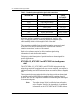
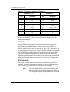
Procedure 10 - LVD installation in the shelf
Step Action
1 Release the clamping bar and blank panel (see Procedure 1).
2 Remove the LVD faceplate.
3 Slide the LVD about two thirds of the way into the shelf.
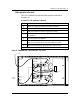
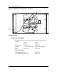
4 Connect the LVD as shown in Figure 22 and 23. (Use 2 X 10 AWG wires
for contactors).
5 Re-install the small LVD faceplate.
6 Push the LVD the remaining distance into the shelf and slide the blank
panel into the shelf between the LVD and the adjacent rectifier.
7 Secure the clamping bar by tightening the two captive screws.
end
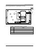
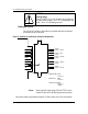
Figure 22 - Embedded shelf - LVD connections - rear access
2
1
8
CHASSIS
GROUND
BAT SENSE
LEADS
TO LOAD
[T]
[B]
BAT
LOAD
BAT RTN