
User Manual Advanced Power Systems MPR25, MPR15 Series


Installation and start-up procedures 61
25A Switch Mode RectifierNT5C06B / C Installation and User Manual
Rectifier power-up
If the factory set voltage limits need to be modified or verified, open the
sense leads of all the rectifier positions to be turned on:
• by disconnecting a quick disconnect tab of TB-1 on the power
shelf
or
• by removing the controller sense fuse (system application)
or
• by setting the dip switches to the OFF position (system
application)
Then refer to the appropriate section for Float Voltage, HVSD or Equalize
adjustments (see User Manual 167-7011-010 Voltage Level Limits for Power
Plants, Rectifiers and Controllers).
If no change is needed continue with the parallel verification procedure.
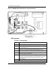
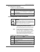
Note:
Quick disconnect tab TB1 is located on the right end side
of the shelf and can be accessed by removing the front
cover (see Figure 24). For system applications, refer to
the appropriate system procedure guide for the fuse or
dip switch location.
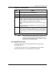
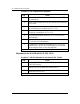
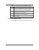
Procedure 11 - Rectifier power-up
Step Action
1 Verify that the DC and AC rectifier circuit breakers are in the OFF position.
2 If no change is needed continue with the “Parallel verification” procedure
found further in this chapter.
3 Turn ON the main AC feed.
4 Turn ON the AC circuit breaker of one rectifier; the rectifier will provide
voltage on the front panel test point terminals.
–end–
Note:
If the rectifier does not provide voltage, check inrush fuse
F1. If the no voltage status remains, refer to the
appropriate troubleshooting section
.