
User Manual Advanced Power Systems MPR25, MPR15 Series


Installation and start-up procedures 65
25A Switch Mode RectifierNT5C06B / C Installation and User Manual
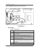
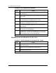
Procedure 15 - Parallel verification
Step Action
1 It is recommended to leave the units functioning for at least 30 minutes
to reach full stability prior to final adjustment.
2 Turn all the DC breakers to the ON position.
3 Turn all the AC breakers to the ON position.
4 To achieve the system float voltage determined by the battery vendor or
the power engineer, increase the FLT potentiometer of the lowest current
rectifier, or reduce the FLT potentiometer of the highest current rectifier
to bring the system float voltage up or down respectively.
The system float voltage shall be read from the system’s meter voltage
reading.
Verify that the system float voltage level is constant while proceeding
through the next step.
5 The load share amperage for each rectifier must be equal. Adjust the
individual float potentiometer as needed to balance the current delivered
by each rectifier. It is recommended that the current from each rectifier
be at least 3 amperes (that is, 9 A for three rectifiers) for best operating
results.
–end–
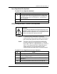
Note:
Some rectifiers may still indicate an RFA (red RFA led).
A red RFA indicates a rectifier delivering less than 0.1 A.
Rotating the float potentiometer (FLT) slightly clockwise
will make the LED illuminate green.
Low voltage disconnect (LVD)
Testing and adjusting the LVD units (NT6C13FA/FH) (Circuit Pack
NT6C13PB Rel. 03).
To verify the LVA and LVD/LVDR operating levels on line, without
disconnecting the load, proceed as indicated in Procedure 16: