
Data Sheet


Bulletin 71.1:MR105
6
that the limits in the Specications section are not
exceeded. Regulator operation within ratings does
not prevent the possibility of damage from external
sources or from debris in the pipeline. A regulator
should be inspected for damage periodically and after
any overpressure condition. Refer to the relief sizing
coefcients in the Specications and the Capacity
Information section to determine the required relief
valve capacity.
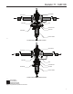
Installation
Vertical installation with the actuator installed directly
above or below the main valve is recommended but for
optimal performance the actuator should be installed
below the main valve. The use of a bleed valve is
recommended for liquid installations that require the
high pressure actuator to be mounted above the main
valve. The unit will operate in horizontal installations
with the actuator on the side, however, this could result
in premature wear of parts. Make sure that ow will
be in the same direction as that indicated by the body
arrow. Orientation of the two vents should always be
down. Vents may be rotated after regulator installation
so that the vent screens are down.
A control line must be installed to allow outlet pressure
to register on the actuator’s diaphragm. The size of the
control line is indicated in the Specications section,
and should be installed four to eight pipe diameter
downstream of the regulator and in an area of pipe that
is free of turbulence.
An instruction manual is provided with every regulator
shipped. Refer to this for detailed installation,
operation, adjustment and maintenance instructions.
Included is a complete listing of individual parts and
recommended spare parts.
Applications
Note
A linear cage is recommended for
applications where low ow stability
is a concern but it will limit the overall
capacity of the regulator.
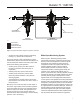
Lube Oil Skids (Figure 3)
Lube oil skids maintain oil ow to bearings, seals and
servo-controls on critical turbomachinery assets such as
air and gas compressors, steam turbines, power recovery
turbines and power generating equipment. These skids
are essential in keeping lube oil clean at all times and
ensure maximum service life for the equipment. Because
it is critical to maintain a constant ow and pressure of
oil to the equipment, it is normally equipped with two
pumps – the main pump and the auxiliary pump, which
will take over in case of main pump failure – and lters.
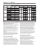
In normal condition, the skids operate in the
following manner:
• Lube oil is stored in the tank at atmospheric pressure.
• It is then fed to the main pump (Pump 1) which
pressurizes the lube oil.
• Oil then goes through a lter.
• After ltration, oil ow is split such that a fraction
is sent to a backpressure regulator to limit the supply
pressure to the pressure reducing regulator. 20%
of the pump rate ows through the backpressure
regulator, sending back oil to the oil tank.
• The pressure reducing regulator decreases the
pressure to a safe and allowable range. Flow
through this regulator is 80% of pump rate.
Figure 3. Lube Oil Skid Diagram
TYPE MR105
PRESSURE REDUCING
REGULATOR
TYPE MR108
BACKPRESSURE REGULATOR
PUMP 1
PUMP 2
FILTER 2
FILTER 1
OIL TANK
TO EQUIPMENT
BEARINGS, SEALS OR
SERVO-CONTROLS
M1202