
Instruction manual


Type MR105
8
!
WARNING
Personal injury, equipment damage or
if the bonnet (key 61, Low-Pressure
Actuator) or lower diaphragm casing
backed off or loosened when installing
control line.
Downstream Control Line Installation
The Type MR105 regulator requires a downstream
control line for proper pressure control. A 1/2 NPT
control line connection is located on the bonnet
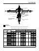
(for low-pressure actuator, see Figure 2) or on
the lower diaphragm casing (for high-pressure
actuator, see Figure 3). For high-pressure actuator
with Quick Opening Cage (liquid service), pipe
bushing (key 76) and restrictor (key 75) should
be installed in the 1/2 NPT control line connection
(see Figure 4).
Connect the downstream control line tubing to
the bonnet or lower casing and run the tubing
approximately 20 in. / 0.5 m downstream. For best
results, the outer diameter of the control line tubing
should be 3/8 in. / 9.5 mm or larger.
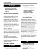
Vent Line Installation
Type MR105 regulators have a 1/2 NPT vent opening on
the spring case. When installed inside a building or if it is
necessary to vent escaping gas away from the regulator,
install a remote vent line in the spring case tapping. Vent
piping should be as short and direct as possible with a
minimum number of bends and elbows. The remote vent
line should be at least 1/2 in./13 mm outer diameter tubing
or 1/2 NPT pipe.
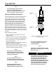
Remove the Type Y602-12 vent and the pipe
bushing (key 76, Figure 6) and attach the vent line
at this location. The other end of the vent line should be
located outside with a screened vent (Type Y602-12 vent
connector). The Type Y602-12 vent connector should
be pointed down and protected as described in the
Installation Location section.
Overpressure Protection
!
WARNING
Personal injury, equipment damage or
leakage due to escaping accumulated
gas or bursting of pressure-containing
parts may result if this regulator is:
could exceed the limits given in the
ratings of adjacent piping or
piping connections.
To avoid such injury or damage, provide
pressure-relieving or pressure-limiting
devices to prevent service conditions
from exceeding those limits.
Type MR105 regulators have an outlet pressure
rating lower than the inlet pressure rating. The
recommended pressure limitations are stamped on
the regulator nameplate. Some type of overpressure
protection is needed if the actual inlet pressure can
exceed the maximum operating outlet pressure
rating. Overpressuring any portion of the regulators
beyond the limits in the Specications section
may cause leakage, damage to regulator parts
or personal injury due to bursting of pressure-
containing parts.
Provide an external overpressure protection if
inlet pressure will be high enough to damage
downstream equipment. Common methods of
external overpressure protection include relief valves,
monitoring regulators, shut-off devices and
series regulation.
If the regulator is exposed to an overpressure condition,
it should be inspected for any damage that may have
occurred. Regulator operation below the limits specied
in the Specications section and regulator nameplate
does not preclude the possibility of damage from
external sources or from debris in the pipeline.
Startup
!
WARNING
To avoid possible personal injury,
equipment damage or leakage due
regulator is installed as instructed in
the Installation section.
Pressure gauges must always be
used to monitor downstream pressure
during Startup.