
Instruction manual


Type MR108
12
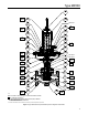
the body ange. Install the valve spring (key 9) and
install the actuator on the body ange by screwing
the adaptor (90 to 130 ft-lbs / 122 to 176 N•m) into
the body ange. The stem will protrude through
the center hole of the valve plug (key 16). Install
and tighten (16 to 18 ft-lbs / 22 to 24 N•m) the
ange nut (key 41) to the stem. Use the wrench
ats on the stem to keep the stem from rotating.
!
WARNING
Personal injury, equipment damage or
if regulator bolts are not tightened to
proper load. Always tighten bolts in an
alternating pattern.
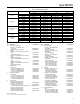
7. Install the body ange on the body (key 1) and
secure it evenly with the stud bolts (key 3). Tighten
to torque value specied in Table 5.
Actuator Maintenance
!
WARNING
Equipment damage, leakage and
may occur if external side forces are
applied to the actuator. Do not stand on
the actuator or apply external loads to
the actuator.
Perform this procedure if it is desired to inspect or
replace the diaphragm or other internal parts or if it
is desired to change the set pressure range of the
regulator by changing the control spring.
!
WARNING
To avoid possible personal injury from
spring or pressure-loaded actuator, make
certain the adjusting screw is completely
backed off or the spring case pressure is
vented prior to disassembly. Otherwise,
the spring load or loading pressure could
forcefully eject the spring case.
Replacing Main Spring
1. Loosen the jam nut (key 72). If a pressure-loaded
actuator is used, remove the sealing washer
(key 71). Using a hand wrench (not an impact
gun), unscrew the adjusting screw (key 73) and
remove it from the spring case(key 70).
2. Loosen and remove the cap screws (key 67) and
lift off the spring case (key 70) from the spring case
spacer (key 66 for Low-Pressure Actuator), upper
casing welding assembly (key 87 for Low-Pressure
Pressure-Loaded Actuator) or upper diaphragm
casing (key 63 for High-Pressure Actuator).
3. Remove the upper spring seat (key 69) and
control spring (key 68). Replace the control spring
if desired.
4. For pressure-loaded spring case, replace the upper
casing welding assembly top O-ring (Low-Pressure
Actuator) or diaphragm casing (High-Pressure
Actuator) O-ring (key 64) if necessary. Install
the new O-ring in the groove on the top surface
of the upper casing welding assembly (key 87)
for Low-Pressure Actuator or upper diaphragm
casing (key 63) for High-Pressure Actuator. If
this is performed only for spring (key 68) and
spring case spacer/upper diaphragm casing
O-ring replacement and no further maintenance
in the actuator and its internal parts is necessary,
proceed to step 23 for Low-Pressure Actuator or
step 20 for High-Pressure Actuator.
For Low-Pressure Actuator Diaphragm Replacement
5. Remove the cap screws (key 57) and hex nuts
(key 58) connecting the casings (key 63 or 87
and 62) and diaphragm (key 56). Lift off the upper
diaphragm casing (key 63) or upper casing welding
assembly (key 87).
6. Unscrew the jam nuts (key 48) and remove them
from the actuator stem (key 40).
7. Remove the Belleville spring washer (key 49),
lower spring guide (key 52) and diaphragm plate
(key 55) from the actuator stem (key 40).
8. Lift off the diaphragm (key 56) from the actuator
stem (key 40) and inspect it for damage. Replace
if necessary. If no further maintenance or
inspection is required, proceed to step 18 to
reassemble the actuator.