
Instruction manual


Type MR108
13
Note
Exercise care to ensure that the
actuator stem (key 40) enters and exits
the lower diaphragm head bore without
pinching, cutting or damaging in any way
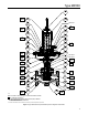
9. Carefully remove the lower diaphragm head
(key 53) from the actuator stem (key 40) so that the
actuator stem threads do not damage the O-ring
inside the lower diaphragm head. Replace the lower
diaphragm head O-ring (key 51) if necessary.
10. Remove the cap screws (key 65) connecting the
lower diaphragm casing (key 62) and the internal
stiffener plate (key 84) to the bonnet (key 61). Lift
the lower casing off of the bonnet.
11. If it is desired to replace the bonnet and stem O-rings
(keys 60 and 47) and bearings (key 46), disconnect
the control line attached to bonnet (key 61). Unscrew
the bonnet (key 61) from the adaptor (key 74).
Remove stem (key 40) from the bonnet by pulling on
the end of the stem without threads.
12. Remove the wiper (key 45, detail Z) on the
threaded (orice side) end of the bonnet (key 61)
to reach the bearing (key 46) and stem O-ring
(key 47). Install the new stem O-ring and bearing
and put back the wiper.
13. Turn the bonnet (key 61) over and install
another stem O-ring (key 47) and bearing (key 46,
detail X) in the top side of the bonnet. Inspect
the bonnet O-ring (key 60) installed in the groove
located on the top surface of the bonnet (key 61) for
any damage and replace if necessary.
!
WARNING
Personal injury, equipment damage or
if the bonnet (key 61) is backed off when
installing control line.
14. Lubricate the bore on both ends of the bonnet
(key 61). Install it over the actuator stem (key 40)
and thread into the adaptor (key 74). Tighten the
bonnet into the body until the connecting pipe
holes in the bonnet are located 90° from the valve
body ends for correct tubing alignment. Do not
loosen the bonnet thread to align the pipe holes.
Always tighten the bonnet to make alignment for
the control line.
Note
Position the bonnet (key 61) such that
located 90° from the valve body ends.
Note
Exercise care to ensure that the
actuator stem (key 40) enters and exits
the bonnet bore without pinching,
cutting or damaging the actuator stem
O-rings (key 47).
15. Lubricate the cap screws (key 65) and use it to
position and secure the lower diaphragm casing
(key 62) and internal stiffener plate (key 84) to
the bonnet (key 61). Tighten the cap screws to a
torque of 10 to 12 ft-lbs / 14 to 16 N•m.
16. The serrated side of the lower diaphragm head
(key 53) should be facing up toward the threaded
end of the actuator stem. Carefully install the lower
diaphragm head (key 53) over the actuator stem
(key 40).
Note
Exercise care to ensure that the actuator
stem (key 40) enters and exits the lower
diaphragm head bore without pinching,
cutting or damaging in any way the lower
17. Place the diaphragm (key 56) over the actuator
stem (key 40) and on top of the lower diaphragm
head (key 53). The convolutions of the diaphragm
should be pointing up.
18. Place the following over the actuator stem (key 40)
and on top of the diaphragm (key 56) in the
following order: diaphragm plate (key 55), lower
spring guide (key 52) and Belleville spring washer
(key 49). The raised inner diameter of the Belleville
spring washer should be pointing toward the
threaded end of the actuator stem.
19. Lubricate the threads of the actuator stem
(key 40) and thread the two jam nuts (key 48)
onto it. Using wreckats, hold the stem and torque
the jam nuts individually. Tighten to a torque of
12 to 14 ft-lbs / 16 to 19 N•m.