
Instruction manual


Type MR108
14
Note
For pressure-loaded actuator option skip
with upper casing welding assembly
(key 87).
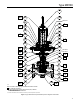
20. Install the upper diaphragm casing (key 63)
or spring case spacer (key 66) assembly
while aligning the bolt circle holes in the upper
diaphragm casing, diaphragm (key 56) and lower
diaphragm casing (key 62).
Note
Exercise care to ensure that the
twisted or wrinkled while compressing
between the upper and lower diaphragm
21. Lubricate the cap screws (key 57) and nuts
(key 58) and carefully insert through holes in the
outer ange of the diaphragm casings (keys 62
and 63) and diaphragm (key 56). Tighten the cap
screws to the hex nuts to a nal torque value of
27 to 29 ft-lbs / 37 to 39 N•m.
22. Place the control spring (key 68) inside the hole
in the upper diaphragm casing (key 63) or upper
casing welding assembly (key 87) and over the
lower spring guide (key 52). The spring should be
sitting on top of the diaphragm plate (key 55).
23. Lubricate the bore on the top of the upper spring
seat (key 69) where the adjusting screw (key 73)
will make contact. Place the upper spring seat on
top of the control spring (key 68).
24. Install the spring case (key 70) over the control
spring (key 68) and upper spring seat (key 69) and
on top of the spring case spacer (key 66) or upper
casing welding assembly (key 87). Align the holes
in the spring case with the holes in the spring case
spacer or upper casing welding assembly while
ensuring the vent assembly (key 26) is aligned with
valve body inlet.
25. Lubricate cap screws (key 67) and use them
to secure the spring case (key 70) to the spring
case spacer (key 66) or upper casing welding
assembly (key 87). Tighten the cap screws
to a nal torque of 25 to 28 ft-lbs / 34 to 38 N•m.
!
WARNING
Personal injury, equipment damage or
Also, main spring (key 68) may go
solid resulting in the backpressure
regulator not opening if jam nut is not
installed and adjusting screw is adjusted
completely down.
26. Lubricate the adjusting screw (key 73) and thread
on the jam nut (key 72). If a pressure-loaded
actuator is used, install the sealing washer (key 71).
Lubricate the adjusting screw and place it into the
spring case (key 70). Thread the adjusting screw
using a hand wrench (not an impact gun) until it
touches the upper spring seat (key 69). Set the
regulator to the desired set pressure according to
the Adjustment procedure.
For High-Pressure Actuator Diaphragm Replacement
5. Remove the cap screws (key 57) and hex nuts
(key 58) connecting the diaphragm casings
(keys 62 and 63) and diaphragm (key 56). Lift off
the upper diaphragm casing (key 63).
6. Unscrew the jam nuts (key 48, detail V) and
remove them from the actuator stem (key 40).
7. Remove the Belleville spring washer (key 49) and
lower spring seat (key 54) from the actuator stem
(key 40).
8. Lift off the diaphragm (key 56) from the actuator
stem (key 40) and inspect it for damage. Replace if
necessary. If no further maintenance or inspection
is required, proceed to step 15.
Note
Exercise care to ensure that the actuator
stem (key 40) enters and exits the lower
diaphragm head bore without pinching,
cutting or damaging in any way the
9. Carefully remove the lower diaphragm head
(key 53) from the actuator stem (key 40). Replace
the lower diaphragm head O-ring (key 51)
if necessary.