Instruction Leaflet IP258 November 2004 Mobrey MSM400 Intelligent Suspended Solids Monitor Software Version 1.1 www.mobrey.
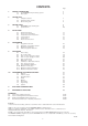
CONTENTS Page 1. PRODUCT INTRODUCTION 1.1 The MSM400 slurry monitoring system 1.2 Description 5 5 5 2. SENSOR TYPES 2.1 Safety Precautions 2.2 Hazardous Area systems 2.3 Quick Start guide 7 7 8 3. CONTROL UNITS 3.1 MSM400 Displays and Keypad 3.2 Specifications 9 9 10 4. INSTALLATION 4.1 Preliminary Checks 4.2 Pipe Section Installation 4.3 Suspended Sensor Installation 4.4 Sensor Cabling 4.5 Control Unit 4.6 Electrical Connections 11 11 11 12 12 13 PROGRAMMING 5.1 Programme Structure 5.
Safety Precautions The following safety precautions should be observed before using this product or working on the attached cables. This MSM400 product is intended for use by qualified personnel who recognize shock hazards and are familiar with the safety precautions required to avoid possible injury. Read the operating information carefully before using the product.
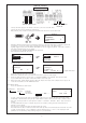
QUICK START Green Black White Black White Green Terminal connections SENSOR CONNECTION 1) 2) 3) L IVE NEUTRAL EARTH MAINS IN Connect the mains supply to the terminal connections L, N and E as shown above. Connect the sensor to the terminals as shown above. With power on, press a button on the key pad as shown below. This will access the main menu.
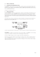
1.0 PRODUCT INTRODUCTION 1.1 THE MSM400 SLURRY MONITORING SYSTEM The MSM400 is an advanced Microprocessor based, HART compatible, versatile slurry measurement system, with a wide range of built-in display, control and alarm function options. The Menu driven programming is simple to use, and allows complete configuration of the unit from the external membrane keypad. Sensor and electrical connections are in a separated terminal housing. This manual is for Software Version 1.1 1.
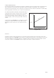
SLURRY CHARACTERISTICS The relationship between the measurement of ultrasonic attenuation and the percentage solids of a particular slurry type is dependent on the density of the slurry particles and their average size distribution. This is known from experience for most slurry types, and is expressed as a number, which is the ultrasonic attenuation in deciBels (dB), per mm gap between sensor faces, per one percent suspended solids.
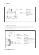
2.0 SENSOR TYPES 2.1 SUSPENDED SENSOR TYPE MSM433 20 Material : Gap size : 316 Stainless steel 100mm, 150mm, 200mm, 300mm, 450mm (others on request) Cable : Dual twin-axial Max. Pressure : 105 kg/cm2 (103 bar) Temperature range : -40°C to + 70°C (others on request) Refer to Sensor safety data for intrinsically safe systems R¾" (BS21:1973) ¾" BSPT 61 Standard gap = 150mm 22 102 Specify gap 50 to 450mm 30 30 Figure 3 : MSM433 Sensor and Specifications 2.
2.3 SENSOR TYPE NUMBERING SYSTEM MSM *** * *** * * / * No. - Indicates special requirement i.e. 1 - with PN16 flanges 7 D V P T 000 A N 433 448 - 7m cable supplied as standard - Customer defined upto 100m (must be clearly stated on order - Spray valve (pipe section only) - No spray valve (pipe section only) - 433 tank mount - Sensor size i.e.
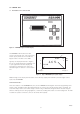
3.0 CONTROL UNIT 3.1 MSM400 DISPLAYS AND KEYPAD Figure 5 : MSM400 keypad and LCD display The MSM400 is wall mounted: the lower section of the housing is for cable connections, and the upper part has the 4 line LCD and keypad controls. The whole unit is IP65. Typically the display will show as in Figure 7, the top line shows whether the programme lock is open together with the time display. The actual value is displayed in the centre. The attenuation figure in decibels is on the bottom line.
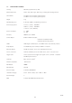
3.2 SPECIFICATIONS--MSM400 Housing ABS with polycarbonate lid, IP65 External dimensions 256.5 wide, 236.7 high, 95.0 deep, including wall mounting brackets Cable Glands 3x 16mm holes and plastic glands supplied 3x 20mm holes and plastic glands supplied Weight 2 kg Wall Mounting holes 6 off Diam 5.0mm (See Drawing Section 4.5) Power supply options 115 V a.c. (±15%) 50 / 60 Hz 230 V a.c. (±15%) 50 / 60 Hz or 24 V d.c. (15 to 30 Volts) Power consumption a.c. 10VA d.c.
4 INSTALLATION 4.1 PRELIMINARY CHECKS The MSM400 system is normally supplied in two packages, one for the MSM400 Control Unit and one for the sensor, whether it is a pipe section or a tank sensor. Take care in handling the pipe section. In particular do not damage the cable or the hose protection for the cable where it enters the sensors. Before installation check that there has been no damage in transit, particularly to the sensor cables.
4.4 SENSOR CABLES The ultrasonic drive signals on the sensor cables are normally at 1MHz and 3.3MHz. The cables are a special construction of two separately screened twisted pairs, designed to meet electromagnetic compatibility regulations. The cables can be extended up to 100 metres, but should use the same cable type, available from Mobrey Measurement. (or consult factory for alternative vendors).
4.6 ELECTRICAL CONNECTIONS All field wiring connections are accessible by removing the lower lid, which is secured by two screws. Note that it is the responsibility of the installer to observe all local regulations and approval requirements, and to use cable to suit the environmental requirements of the particular application. Obtain and check any hazardous area work permits required before applying power to the MSM400.
SENSOR CONNECTIONS The sensor connections are on the left side of the terminal enclosure. Each sensor has two screened twisted wire pairs, either as one dual pair cable, or two separate pairs One pair is connected to the TX (transmit) group and the other to the RX (receive) group. The sensors are symmetrical so either of the pairs can be chosen as TX or RX. The two cores in each group are connected to A and B, the polarity is not important.
TRIGGER INPUTS There is trigger input D1. This can be used to control desludge and other functions see programming section. The digital trigger input is connected as shown below: 5V 10 D1 8 0V 7 A voltage greater than 2V on Terminal 8 (D1) causes trigger input 1 to be active. This can be achieved by connecting to terminal 10 (5V) via an external switch or relay. The maximum voltage should not exceed 28V.
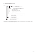
5.0 PROGRAMMING 5.1 The operation of the MSM400 is controlled by means of programmable parameters. These are stored in memory and may be set by the user to define variables such as calibration scale factors, set points, and modes of operation. The parameters are accessed using the keypad, by means of a menu system as shown below. (Parameters may also be edited remotely using the HART protocol. See Appendix N). For a full listing of the menu structure refer to Appendix A1. 5.
3. Use the down arrow key (ß) to highlight the TOGGLE RUN option and select it using the “ENT” key. The TOGGLE RUN screen is then displayed: TOGGLE RUN 4. 5. 6. 7. 8. 9. 10. To open (or close) the padlock press ENT as required. Press ESC to return to the main menu. Programming is now enabled. From the Main Menu screen, use the down arrow key (ß) to highlight the SETUP option and select it using the “ENT” key In the SETUP menu use the ß key to highlight the OUTPUT option and select it.
17. The value of the digit may now be incremented or decremented by pressing ⇑ ⇓. RL1 On Point% 003.00 0 0 P411 18. Press ENT to store the value. The highlighting will disappear. If an invalid number is entered then the display will revert to the last valid value. 19. The relay off point is programmed in the same way (all other numeric parameters are programmed in a similar way). When programming is complete, return to the TOGGLE RUN menu and close the padlock.
6.2 RECHECKING ZERO It is recommended that the zero is checked regularly. The frequency of re-calibration is dependent on the process. However, it is suggested that this be done at least every 6 months. CALIBRATION METHODS AUTO CAL 6.3 AUTO CAL - ZERO SETTING PROCEDURE AUTOCAL is a simple step by step calibration routine in which the user is guided through the calibration process by a series of user friendly screens. AUTOCAL is the recomended calibration proceedures.
The display will show the following. SET ZERO In clear liquor please wait 0 0 After a few seconds the display will show the following. SET ZERO In clear liquor Press ENT to set 23.1dB 26.2dB 0 0 The two dB values at the bottom of the screen are the zero values for the operating frequencies of the sensor (1MHz and 3.3MHz). Once the ENT key is pressed the zero is set. All zero reference data is now saved together with the date of zero calibration.
After a few secnds the display will show the following. SET SPAN In sample 1 Press ENT to set 33.6dB 44.2dB 0 0 The bottom line of the display shows the attenuation caused by the sludge. During a desludge these readings will fluctuate due to random variations in the sludge density. When the readings are reasonably stable press ENT at the same time that a sample is taken. This will store the reading from the sensor.
6.6 MAXIMUM % SOLIDS To complete the calibration and to enable the system to automatically select the optimum frequency of operation., it is necessary to set the maximum % solids that the system is required to measure. In the AUTOCAL Menu, select ‘Max % Solids’ (P 160) and enter the value required. If the maximum % solids are low then the system will choose the higher operating frequency (3.3 MHz). This will give the best possible resolution. If the maximum % solids are higher than can be measured at 3.
Under stable operating conditions, the objective is to record the MSM400 attenuation figure, and immediately take a sample of the slurry present between the sensor faces.This is then analysed in the lab, to derive the solids %, and this % value is later linked to the previous ultrasonic attenuation. The objective is to take three separate readings and samples, which are averaged by the Microprocessor.
7.0 PROGRAMMING THE MSM400 FUNCTIONS DUTY (MODE) DESLUDGE MODE. There are several methods of starting, stopping, overriding and stopping early a de-sludge operation. The desired options can be selected in the SETUP – DUTY (Mode) – DESLUDGE menu. The following table explains the various options. (PV = process value i.e.
Starting desludge This is controlled by the “Start on” function in the DESLUDGE menu. This should be set to “Time”. Cycles will begin at “Start Time 1” and repeat at intervals “Interval 1” until “Start Time 2”. After this, cycles will repeat at intervals “Interval 2”. This allows desludging to be done at different intervals during day and night, for example. In the example “Start Time 1” is set to 7:30 and “Interval 1” to 5 hours.
8. 9. Scroll down to “Start time #1” and press ENT. Use ⇒ key to highlight the first digit in the time, scroll up and down to edit the digit. Use the left and right arrows to move to the next digit (the time is programmed in hours and minutes h : m). When the correct start time is shown on the display press ENT. Start Time 7:30 10. 11. 12. 13. 14. 15. 16. 17. 18. #1 h:m P254 0 0 Press ESC to return to the DESLUDGE menu. Scroll down to “Interval #1” and press ENT.
7.1 OUTPUTS 7.2 CURRENT OUTPUT The operation of the current output is set up by four different parameters and is always controlled by the process variable (PV), which is normally % suspended solids. These are found in SETUP – OUTPUT – CURRENT OUTPUT. 1. 2. 3. Lower range value (Low range val) This is the value of PV which corresponds to the minimum current output, either 0 or 4mA Upper range value (Up range val) This is the value of PV which corresponds to the maximum current output, 20mA.
c) ALARM The relays can be set for alarm mode conditions by selecting the option in SETUP – OUTPUT – RELAY – Relay * mode. See the section below titled ALARM. 7.4 ALARM There are six different alarms in the SETUP - OUTPUT - ALARM menu. Each alarm can be set to operate a relay, or drive the current output, or both, or neither to the following states. 1. 2. Current output - 3.6mA, 21mA, Hold as defined in “Alarm action” in the CURRENT OUTPUT menu.
The display has a backlight, which can be set to On, Off or Auto. When set to Auto the backlight automatically turns off after a few minutes if no keys are pressed. 7.7 ENGINEERING FREQUENCY SET The frequency of operation is normally set automatically. Under certain conditions it may be advantageous to force the control unit to operate at either 1 MHz or 3.3 MHz. This should not be done without consulting the factory. 7.
8.0 HART SMART Communications The MSM400 is compatible with the HART digital signalling system, either as well as the 4-20 mA output , or on a Bus system. MSM400 supports Version 5.x of the HART protocol, and is fully supported by the MOBREY CK-1 HHC (Hand Held Communicator) and by the UNIVERSAL 275 HHC. It is normally necessary to load the Universal HHC with the transmitters Device Description to access anything more than the basic transmitter information-contact Mobrey Measurement for details.
FULL MENU STRUCTURE - LOCATION OF PARAMETERS MAIN MENU SUB MENU 1 SUB MENU 2 PARAMETER DESCRIPTION TOGGLE RUN CALIBRATION (specific) Par No. Toggle AUTOCAL MANUAL ENTRY SENSOR ZERO REF SPAN LAB VALUES SETUP APPENDIX A1 DUTY (Mode) PV Calculation DESLUDGE INPUT SENSOR INPUT OUTPUT CURRENT OUTPUT RELAY SET ZERO SET SPAN LAB VALUES Max % solids Sensor Gap Sludge Type dB Factor @ 1MHz dB Factor @ 3MHz Zero Ref @ 1MHz Zero Ref @ 3.
MAIN MENU SUB MENU 1 SUB MENU 2 PARAMETER DESCRIPTION Par No.
APPENDIX A2: FULL LIST OF FUNCTIONS Parameter list and description P=Parameter, D=Diagnostic Display Parameter Parameter No. P100 P101 P102 P103 P120 P121 P122 P123 P124 Description Sensor Gap in mm. This is a user entered parameter (optional). This value is ignored when an alternative span calibration is caried out (i.e. method two or three). Sludge type The user can select from a list of sludge type to set up the span for the calibration procedure (optional).
Parameter No. Description Min. value Max. value Default Ex-Factory P130 P131 P132 P133 P134 P135 P140 P141 P142 P150 P151 P152 P160 P200 Span 1 @ 1MHz Measured attenuation Span 1 @ 3.3MHz Measured attenuation Span 2 @ 1MHz Measured attenuation Span 2 @ 3.3MHz Measured attenuation Span 3 @ 1MHz Measured attenuation Span 3 @ 3.
Parameter No. Description P400 Lower range value The mA set point for minimum PV in selected units Upper range value The mA set point for maximum PV in selected units Alarm action The is the value that the current will drive to on alarm action. The alarm action is programable and is selected from list (3.6/21mA/hold last reading).
Parameter No.
Parameter No. Description Min. value Max.
APPENDIX A3 : HART and PSION Operating Instructions 1.0. HART CONSIDERATIONS Special Considerations for HART If the HART communications facility built into the control unit will be used at the time of installation or during its future working life, then it is essential that a resistive load of at least 250 Ohms is connected in the supply cable. This may be provided by other devices in the loop (Chart recorder, meter, etc.) or more usually by installing a standard 270 Ohm 0.
2.0 SMART COMMUNICATION WITH THE MOBREY MSM400 With a SMART HHC, you can make adjustments and calibrate your MSM400 at any point on the two wire connection to the control unit. You can also make many other adjustments and obtain operational and diagnostic information using the HHC. Alternatively, Mobrey have a PC based software package called Mobrey H-View which allows you to make adjustments and obtain readings through a standard PC. Contact Mobrey or your local agent for details.
2.2 Further customisation using the SMART HHC There are some other features of the control unit that can be changed at this stage: Identity The following parameters can be recalled from the “Info” menu, and those shown * below can be site configured :P701 P710 P700 P702 P722 P760 P660 MESSAGE TAG DESCRIPTION DATE FINAL ASSY No. SENSOR SERIAL No PASSWORD *general purpose 32 character message *control unit identifier (8 characters) *E.G.
Appendix D D. HANDHELD COMMUNICATOR – MOBREY – CK* D.1.0. Hand Held Communicator – Assembly Instructions The MOBREY-CK* SMART Hand Held Communicator is supplied as a kit of items (Figure DI) which are assembled as follows: D.1.1 Remove the lower sliding cover (1) of the Psion organiser (2) completely to expose the battery compartment lid (3) at the base of the keypad, and the two slots for Datapaks behind the right hand side of the keypad. D.1.
Fig DII.
Fig D1 : MOBREY-CK* HHC assembly IP258 43
Technical Notes: 1. At no time can the SMART communicator be attached across A1-A2, since the DC supply effectively short circuits the transmitted and returned digital communications signals. 2. The minimum DC Voltage V1 required for satisfactory 20mA loop operation can be calculated from the formula – V1 > 2.5 + V2 + [20 x 10-3 ]x (R1 + R2 + R4 +R5) D.3.6.3.
D.5.0. Hand Held Communicator : Operation Language Initially the Psion Organiser will power up and display the Psion Copyright message, when the ON button is pressed. Then a choice of languages will be offered. This applies to the operation of the Psion Organiser functions only, MSM400 programme, although Datapaks will be available from MOBREY in different languages.
D.6.0 How to drive a Psion based SMART Communicator Familiarity with the Psion The Psion is supplied with several manuals to described its function. The main keyboard functions that are important are the yellow keys. Press “ON” and see the functions of the arrows to move the cursor around the selections in the menu. Press “EXE” to see the Psion functions.
When an MSM400 Control unit is located on the loop, this is identified and further instructions awaited. MSM400 FOUND TAG TANK 1 ACCESS (Y)es or (N)o Alternatively an Unknown Instrument may have been found, i.e. a HART instrument that is not a MSM400 or MSP100 or MLT100. This will cause a similar message and prompt to be displayed.
Future work on this data can be carried out whilst the SMART communicator is connected to the loop, in which case all changes will be immediately sent to the MSM400, or after disconnection of the Communicator, in which case the amended programme will have to be stored in the “OFFLINE” register of the communicator. The Psion Organiser has four separate registers of data relating to the MSM400 control unit. These registers are named WORKING, SAFE, OFF-LINE and DEFAULT, and are explained in Section D13.0.
D7.1 Monitor/Display Parameters – D** Access and programme structure The Display Parameters (D***) are separated into several blocks according to the type of operator read only information. See menu structure in the main body of the manual. All the Display parameters can be accessed directly from the FUNCTION menu by selecting the appropriate identification number, e.g. D240. ENTER PARAMETER No D The live data recalled on the displays are updated continuously by the SMART Communicator every 0.
WORKING REGISTER Holds the same value as is currently in the control unit. SAFE REGISTER Use as a backup, can only be sent to the same control unit as it was loaded from. OFF-LINE REGISTER General purpose register, use to program a control unit offline or transfer data between transmitters of the same type. DEFAULT REGISTER The normal ex-factory values.
HAND HELD COMMUNICATOR REGISTERS D9.0 SAFE, WORKING, OFFLINE, DEFAULT, Registers Introduction to Registers From the FUNCTION screen, whilst interrogating an MSM400 control unit, there is a selection titled “BACKUP”. This allows the data now stored in the WORKING register (i.e. the MSM400 control unit data) to be transferred to a separate secure memory, to either retain it while making changes to the MSM400 control unit (i.e.
An obvious precaution in the above procedure after loading the WORKING register with the current MSM400 control unit data, is to transfer this data to the SAFE register in case the OFF-LINE sorted new programme does not give the expected result – if necessary the MSM400 can be restored to its original programme status by transferring the SAFE register data to the WORKING register. The OFF-LINE register is retained when the communicator is disconnected from the loop or powered down.
D.9.1 Printout or PC transfer of MSM400 programme data When used “Off-Line” the Hand Held Communicator can be instructed to transfer the programme memory into a PC or print a list of the parameters and the values in the working register on a paper printer. This is achieved using the Standard Psion COMMS LINK routines and interfaces. To send or receive data from a PC the COMMS LINK must be plugged in and connected to the PC port and the CL program must be running on the PC.
Control unit Status Messages Further operational alarm/error messages are shown on the LCD when any display parameter is selected. When either Readings or Diagnostic parameters (D200 - D265) are shown, the SMART Communicator is interrogating the MSM400 control unit every 0.5 seconds, and the information returned includes various message signals concerning the current status of the returned echo.
“PASSWORD NOT OPEN” - If the Password in the MSM400 control unit memory is set “CLOSED”, then it will not be possible to load data from the SAFE or OFFLINE register. The Password protects the data in the MSM400. “INVALID ACTION NOT THE SAME INSTRUMENT” - If an attempt is made to transfer SAFE register data to the WORKING register of an MSM400 control unit which is not the origin of the SAFE register data, this will not be allowed.
OFF-LINE MEMORY TRANSFERS D0 - D8 : MSM400 IP258 56
(pre change) value : this prompts the operator to re-enter the required new value. It is important that the Parameter is re-entered, to ensure that the Working register memory in both the Psion and the MSM400 contain the same data. If either of the above two Outgoing or Reply Comms Error messages occurs in a Backup menu transfer between registers, it is advisable to repeat the Backup operation to complete the data transfer, or check that the memory has been transferred correctly.
D11.2 Trim Current If the procedure shown above suggests that there is a calibration difference between the MSM400 output and other current monitoring equipment on the loop, it will be necessary to use a calibrated meter to establish which unit is in error. Using the “Set current” routine of the MSM400 can be instructed to provide outputs between 4 and 20mA that the MSM400 considers correct.
D13.0 SMART Interfaces – Compatibility D13.1 Introduction The MOBREY MSM400 SMART slurry monitoring system unit uses the HART digital communications protocol. This was originally developed by Rosemount Inc. in USA, and uses Bell 202 Frequency Shift Key signalling on top of a 2 wire DC loop supply. The MOBREY MSM400 system conforms to Revision 5.1 of the HART protocol. Various other manufacturers use this same HART protocol and produce sensor equipment that can be attached to 4-20mA or digital loops.
Instruction Leaflet IP258 November 2004 Level The Emerson logo is a trade mark and service mark of Emerson Electric Co. Rosemount is a registered trademark of Rosemount Inc. Mobrey is a registered trademark of Mobrey Ltd. All other marks are the property of their respective owners We reserve the right to modify or improve the designs or specifications of product and services at any time without notice.