
User`s guide


Copyright © 2004 EIM COMPANY, INC. • 13840 PIKE ROAD • MISSOURI CITY, TX. 77489
Page 108
Controlinc 1746-C (Version 5.21) Network Master Users Guide (2004-11-18)
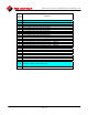
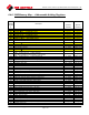
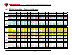
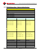
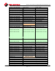
6.4.5. 320B Memory Map … Table for Coils & Inputs
Register BIT 15 BIT 14 BIT 13 BIT 12 BIT 11 BIT 10 BIT 9 BIT 8 BIT 7 BIT 6 BIT 5 BIT 4 BIT 3 BIT 2 BIT 1 BIT 0
Pulsed
Control
Mode
VFD Starter
(Precision
Ctl Mode)
Reserved
0
no-op
Modulating
Control
indicator
(CAM08)
Cmd to
Enter ESD
Mode
Cmd to
CLOSE
Valve
Cmd to
STOP
Valve
Cmd to
OPEN
Valve
COM 2
Enable
Relay
COM 1
Enable
Relay
User Output
Relay 2
User Output
Relay 1
ESD /
Monitor
Relay
SSR/VFD
Relay
Open Valve
Relay
Close Valve
Relay
0
(coils)
R/W 15 R/W 14
R/W 13
R/W 12
R/W 11 R/W 10 R/W 9 R/W 8
RO 7 RO 6 RO 5 RO 4 RO 3 RO 2 RO 1 RO 0
Unit
Alarm
0
Actuator
Self-Test
Alarm
Local ESD
Alarm
Phase
Monitor
Alarm
Thermal
Overload
Alarm
Power
Monitor
Alarm
Valve Stall
Alarm
TSC
Alarm
TSO
Alarm
SS in
Remote
Position
SS in Local
Position
Valve is
Closing
Valve is
Opening
LSC is
tripped
LSO is
tripped
1
(coils)
RO 31 RO 30 RO 29 RO 28 RO 27 RO 26 RO 25 RO 24 RO 23 RO 22 RO 21 RO 20 RO 19 RO 18 RO 17 RO 16
Config
Conflict
Error
Trigger
ESD on
Lost Comm
Trigger
ESD on
Local ESD
Trigger
ESD on
Network
Command
ESD –
STOP
with Relay
ESD –
OPEN
with Relay
ESD –
CLOSE
with Relay
ESD –
OPEN
No relay
ESD –
CLOSE
No relay
Reserved
0
no-op
Enable
SSR Starter
Passcode
Enabled
Enable
Monitor
Relay
Operations
4-20mA
position
feedback on
AO1
Enable
Log Jam
Enable
Torque
Seating
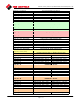
2
(coils)
R/W 47
R/W 46 R/W 45 R/W 44 R/W 43 R/W 42 R/W 41 R/W 40 R/W 39
R/W 38
R/W 37 R/W 36 R/W 35 R/W 34 R/W 33 R/W 32
Relay #2
override –
work with
ESD
Relay #2
NC
Relay #1
active at
LSA
Relay #1
active at SS
in Local
Relay #1
active at SS
in Remote
Relay#1
override –
work with
ESD
Relay #1
NC
Reserved
0
no-op
Reserved
0
no-op
Reserved
0
no-op
AIN 3 Fault
Move to
Default
AIN 2 Fault
Move to
Default
AIN 1 Fault
Move to
Default
Setpoint
Source –
AIN3
Setpoint
Source –
AIN2
Setpoint
Source –
AIN1
3
(coils)
R/W 63 R/W 62 R/W 61 R/W 60 R/W 59 R/W 58 R/W 57
R/W 56 R/W 55 R/W 54
R/W 53 R/W 52 R/W 51 R/W 50 R/W 49 R/W 48
Cmd - Load
Factory
Defaults
CPU has
Reset
Cmd - Save
Torque
Profile
Enable Back
Seating
Enable
MRTU
Operations
Reserved
0
no-op
Reserved
0
no-op
COM 2
Alarm
Enable
COM 1
Alarm
Enable
COM 2
Even Parity
COM 2
Odd Parity
COM 1
Even Parity
COM 1
Odd Parity
Relay #2
active at
LSB
Relay #2
active at SS
in Local
Relay #2
active at SS
in Remote
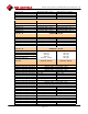
4
(coils)
R/W 79
R/W 78
R/W 77
R/W 76 R/W 75
R/W 74 R/W 73
R/W 72 R/W 71 R/W 70 R/W 69 R/W 68 R/W 67 R/W 66 R/W 65 R/W 64
Reserved
0
no-op
User Input
#2 Status
User Input
#1 Status
Aux Alarm
Input
Local ESD
Alarm
Phase
Monitor
Alarm
Thermal
Overload
Alarm
Power
Monitor
Alarm
TSC
Status
Indicator
TSO
Status
Indicator
SS in
Remote
Position
SS in Local
Position
Contactor
Aux Close
is Made
Contactor
Aux Open
is Made
LSC is
Tripped
LSO is
Tripped
5
(inputs)
RO 15
RO 14 RO 13 RO 12 RO 11 RO 10 RO 9 RO 8 RO 7 RO 6 RO 5 RO 4 RO 3 RO 2 RO 1 RO 0
Unit
Alarm
0
Actuator
Self-Test
Alarm
Local
ESD
Alarm
Phase
Monitor
Alarm
Thermal
Overload
Alarm
Power
Monitor
Alarm
Valve Stall
Alarm
TSC
Alarm
TSO
Alarm
SS in
Remote
Position
SS in Local
Position
Valve is
Closing
Valve is
Opening
LSC
Tripped
LSO
Tripped
6
(inputs)
RO 31
RO 30
RO 29 RO 28 RO 27 RO 26 RO 25 RO 24 RO 23 RO 22
RO 21 RO 20 RO 19 RO 18 RO 17 RO 16
7 (NOT BIT ADDRESSABLE … VALVE POSITION INDICATOR … 0 100% IN 1% INCREMENTS) (Read Only)
Phase
Monitor
Alarm
Local ESD
Input Alarm
TSC
Alarm
TSO
Alarm
COM 2
Alarm
COM 1
Alarm
Power
Monitor
Alarm
Thermal
Overload
Alarm
Unit
Alarm
SS in
Local or Off
Position
Valve Stall
Alarm
Valve is
Closing
Valve is
Opening
Valve
Stopped
LSC is
Tripped
LSO is
Tripped
8
(inputs)
RO 47 RO 46 RO 45 RO 44
RO 43 RO 42
RO 41 RO 40 RO 39 RO 38 RO 37 RO 36 RO 35 RO 34 RO 33 RO 32
9 – 11 NON-BIT ADDRESSABLE MEMORY
Reserved
no-op
Reserved
no-op
Reserved
no-op
Reserved
no-op
Reserved
no-op
Reserved
no-op
Reserved
no-op
Reserved
no-op
Reserved
no-op
Reserved
no-op
Reserved
no-op
Software
Based ESD
is Active
AIN 3
Signal
Fault
AIN 2
Signal
Fault
AIN1
Signal
Fault
SETUP
Mode
Indicator
12
(inputs)
RO 63 RO 62 RO 61 RO 60 RO 59 RO 58 RO 57 RO 56 RO 55 RO 54 RO 53 RO 52 RO 51 RO 50 RO 49
RO 48
13 END OF BIT ADDRESSABLE MEMORY