
User`s guide


Copyright © 2004 EIM COMPANY, INC. • 13840 PIKE ROAD • MISSOURI CITY, TX. 77489
Page 122
Controlinc 1746-C (Version 5.21) Network Master Users Guide (2004-11-18)
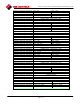
Example (in byte order) of a request to force a series of ten coils …
starting at coil 20 (internal coil number 19 … 13 hex) in slave device
17.
1. Slave Address 11
2. Function 0F
3. Coil Address Hi byte 00
4. Coil Address Lo byte 13
5. Quantity of Coils Hi byte 00
6. Quantity of Coils Lo byte 0A
7. Data Byte Count 02
8. 1
st
Data byte (Coils 27-20) CD
9. 2
nd
Data byte (Coils 29-28) 01
10. CRC Hi byte ––
11. CRC Lo byte ––
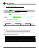
The query data contents are two bytes: CD 01 hex
(1100 1101 0000 0001 binary).
The binary bits correspond to the coils in the following way:
Bit: 1 1 0 0 1 1 0 1 0 0 0 0 0 0 0 1
Coil: 27 26 25 24 23 22 21 20 – – – – – – 29 28
The first byte transmitted (CD hex) addresses coils 27-20, with the
least significant bit addressing the lowest coil (20) in this set.
The next byte transmitted (01 hex) addresses coils 29-28, with the
least significant bit addressing the lowest coil (28) in this set.
Unused bits in the last data byte should be zero–filled.
6.5.2.5. Modbus Function Code 15 (0x0F) … Set (Force) Multiple Coils
Using function code 15, the Modbus master (host) may directly address and write a range of consecutive
bits that indicate coils … to turn them ON or OFF.
This is very similar to function code 05 that deals with single coils (register bits) except that function code
15 deals with a consecutive range of bits (coils).
For more information, refer to the previous section that identifies “
Function code 05 … Set (Force) Single
Coil”
Also, refer to the previous section that identifies “
Standard Coils”
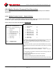
Response example (in byte order):
1. Slave Address 11
2. Function 0F
3. Coil Address Hi 00
4. Coil Address Lo 13
5. Quantity of Coils Hi 00
6. Quantity of Coils Lo 0A
7. CRC Hi byte ––
8. CRC Lo byte ––