
User`s guide


Copyright © 2004 EIM COMPANY, INC. • 13840 PIKE ROAD • MISSOURI CITY, TX. 77489
Page 67
Controlinc 1746-C (Version 5.21) Network Master Users Guide (2004-11-18)
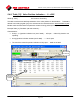
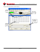
5.4.10. Table [12]: Discrete Input Statuses
Words [4
63] PLC access: Read Only.
This table contains the status indications of the discrete inputs on 320A/B systems. Each bit in each
word in the table indicates the status of a particular discrete (hardwired) digital input for a particular
actuator. This data is derived from holding register [05] in the actuators and is retrieved with the
“standard data request
” - Modbus read command when the particular actuator is being polled
(scanned).
If a TEC2000 was polled, the TEC2000 system correlates appropriate values to the bits being returned.
This status word can be “bit parsed” to give:
• Bit-0: LSO (Limit Switch – Open) switch input is active (is tripped)
• Bit-1: LSC (Limit Switch – Close) switch input is active (is tripped)
• Bit-2: AUX Open Contactor input is active (is engaged)
• Bit-3: AUX Close Contactor input is active (is engaged)
• Bit-4: SS in Local Position input is active (is tripped)
• Bit-5: SS in Remote Position input is active (is tripped)
• Bit-6: TSO (Torque Switch – Open) input is active (is tripped) … not the alarm!
• Bit-7: TSC (Torque Switch – Close) input is active (is tripped) … not the alarm!
• Bit-8: Power Monitor Alarm input is active.
• Bit-9: Thermal Overload Alarm input is active
• Bit-10: Phase Monitor Alarm input is active (only if Phase Sentry is Installed)
• Bit-11: Local (Hardwired) Alarm input is active
• Bit-12: AUX Alarm input is active
• Bit-13: User Input #1 is active
• Bit-14: User Input #2 is active
• Bit-15: Reserved … no operation.
Note: Bit-0 is the LSB in the word. Bit-15 is the MSB in the word.
Some of these bit indications are repeats of those in table [2]. However, not all.