NetSure 211 C23 Embedded Power Supply System User Manual Version V1.0 Revision date September 15, 2009 BOM 31012177 Emerson Network Power provides customers with technical support. Users may contact the nearest Emerson local sales office or service center. Copyright © 2009 by Emerson Network Power Co., Ltd. All rights reserved. The contents in this document are subject to change without notice. Emerson Network Power Co., Ltd. Address: No.1 Kefa Rd.
Safety Precautions To reduce the chance of accident, please read the safety precautions very carefully before operation. The "Caution, Note, Warning, Danger" in this book and on the product do not represent all the safety points to be observed, and are only supplement to various safety points. Therefore, the installation and operation personnel must receive strict training and master the correct operations and all the safety points before operation.
IV. ESD Note The static electricity generated by the human body will damage the static sensitive elements on PCBs, such as large-scale ICs. Before touching any plug-in board, PCB or IC chip, ESD wrist strap must be worn to prevent body static from damaging the sensitive components. The other end of the ESD wrist strap must be well earthed. V.
Others I. Safety Note Noti Warning ce When replacing power input fuses of monitoring module and power distribution units, use the same type fuses to meet the safety requirement. II. Sharp object Warning When moving equipment by hand, wear protective gloves to avoid injury by sharp object. III. Power cable Note Noti Warning ce Please verify the cable labels before connection. IV. Signal cables Note Noti Warning ce The signal cables should be routed at least 150mm away from power cables.
Contents Chapter 1 Overview ............................................................................................................................................................ 1 1.1 Model Description ................................................................................................................................................. 1 1.2 Composition And Configuration .........................................................................................................................
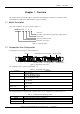
Chapter 1 Overview Chapter 1 Overview This chapter introduces model description, composition and configuration, and features of NetSure 211 C23 embedded power supply system (abbreviated as ‘system’ hereinafter). 1.1 Model Description The model description of the system is given in Figure 1-1. NetSure 211 C 2 3 Version No. The number of the rectifier in the typical power supply system: 2 Region: China Type of the rectifier: R48-1000 Brand name of the system Figure 1-1 Model description 1.
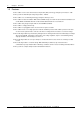
2 Chapter 1 Overview 1.3 Features The rectifier uses the active Power Factor Compensation (PFC) technology, raising the power factor to 0.99. The system has wide AC input voltage range: 90Vac ~ 290Vac. The rectifier uses soft switching technology, raising the efficiency to 91%. The rectifier has ultra-low radiation. With advanced EMC design, the rectifier meets international standards such as CE, NEBS and YD/T983. Both the conducted and radiated interference reach Class B.
Chapter 2 Installation Instruction 3 Chapter 2 Installation Instruction This chapter introduces installation and cable connection. Before installation, please read through safety regulations, and then follow the instructions provided in this chapter to carry out the installation and cable connection. 2.1 Safety Regulations Certain components in this system carry hazardous voltage and current. Always follow the instructions below: 1.
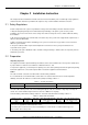
4 Chapter 2 Installation Instruction Table 2-3 Load cable CSA selection Load route rated Max. output Min. cable Max. cable length (volt drop: Max. cable CSA current current CSA 0.5V, with min. CSA) 2 10A 5A 1.5mm 8m 3.3mm2 2 20A 10A 1.5mm 4m 3.3mm2 Note: The specs are applicable at ambient temperature of 25°C Max. cable length (volt drop: 0.5V, with max. CSA) 20m 10m The CSA of the system earth cable should be the same as that of the largest power distribution cable and not less than 2.5mm2.
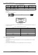
Chapter 2 Installation Instruction 5 43 32 461 482 Front view 279 428 Top view Figure 2-2 Installation dimensions (unit: mm) 2.4 Electrical Installation 2.4.1 Connecting Power Cables Danger Danger 1. Switch off all MCBs and fuses before the electrical connection. 2. Only the qualified personnel shall do the power cable connection. 3. The batteries may have dangerous current.
6 Chapter 2 Installation Instruction Connection Cable From To DC output cable DC output terminals Load connection terminals Battery cable Battery string Battery terminals After the cable connections, reinstall the plastic cover of the AC input terminals. Note The connection terminals of the AC input cables must be wrapped with insulating tube, to prevent electric shock caused by getting in touch with bare metal parts of the connection terminals exposed outside the plastic cover. 2.4.
Chapter 3 Installation Testing 7 Chapter 3 Installation Testing This chapter introduces procedures of installation testing. The corresponding safety rules shall be adhered to in the test. 3.1 Installation Check And Startup Before the test, inform the chief manufacturer representative. Only the trained electrical engineer shall conduct the system testing. Remove metal objects that may cause shortcircuit, such as rings, watches, and so on.
8 Chapter 3 Installation Testing 3.2 Basic Settings When the system is put into service for the first time, the parameters of the monitoring module must be set based on the actual system configuration, battery number and capacity, user’s charge current limiting and other functional requirements. Only after that can the monitoring module display system operation information and control the output. To change the settings, enter the main menu Settings (password: 1) Battery Settings Batt.
Chapter 3 Installation Testing System operation status check There should be no alarms during normal system operation. The system operation status check can be conducted through the monitoring module. Check item The system model is correct (48V/SET) The monitoring module should display the correct AC voltage The difference between the voltage displayed by the monitoring module and the actual value should be less than ±0.
10 Chapter 4 Alarm Handling Chapter 4 Alarm Handling This chapter describes the handling of alarms, as well as the preventive maintenance of the system during system daily operation. The maintenance personnel must have adequate knowledge about the system. Note 1. The maintenance must be conducted under the guidance of related safety regulations. 2. Only the trained personnel with adequate knowledge about the system can maintain the inner part of the system. 4.
Chapter 4 No. Alarm 7 LVD2 8 Rect Failure 9 Rect Protect 10 Rect Fan Fails 11 Rect Not Respond 12 Batt Over Temp Alarm Handling 11 Handling method 1. Check if there is a mains failure, and the battery voltage is lower than the ‘BLVD’ value, or the battery discharge time is more than the ‘BLVD Time’. 2. Check if someone manually disconnected the battery from the system The red indicator on the rectifier will turn on. 1. Reset the rectifier by powering it off and then on again. 2.
12 Chapter 4 Alarm Handling Symptom Monitoring module alarms Causes Handling methods Check whether the rectifier communication is normal. If not, check whether the communication cable is in normal connection. If the communication is normal while the protection indicator is on, replace the rectifier Change the position of the faulty module with normal module.
Chapter 4 Alarm Handling 13 After a brief delay, the rectifier RUN indicator will turn on and the fan will start running. 5. Check that the new rectifier works normally. You should make sure that: 1) The monitoring module recognizes the new rectifier. 2) The new rectifier shares current with other rectifiers. 3) When this new rectifier is pulled out, there is a corresponding alarm and the monitoring module displays the alarm. If the new rectifier passes all the above tests, the replacement is a success.
14 Appendix 1 Technical Data Appendix 1 Technical Data Table 1 Technical data Parameter category Environmental AC input DC output AC input alarm and protection DC output alarm and protection Parameter Operating temperature Storage temperature Relative humidity Altitude Pollution level Others Input phase voltage Input voltage range Input frequency Max input current Power factor Over-voltage level Rated output voltage Output voltage range Output current Total regulation Efficiency Noise (peak-peak) W
Appendix 1 Parameter category Parameter Output delay Fan speed Rectifier Over-voltage protection Temperature derating CE RE Immunity to EFT Immunity to ESD Immunity to Surges Acoustic noise Insulation resistance EMC Insulation strength ROHS Mechanical Size (W ×D ×H) (mm) Weight (kg) System Rectifier System Rectifier Technical Data 15 Description Output voltage can rise slowly upon rectifier start up.
Appendix 2 Wiring Diagram Appendix 2 Wiring Diagram 1 LOAD OUTPUTS + 2 DA411X1 PCB A LOAD1- LOAD2- LOAD3- LOAD4- LOAD5- LOAD6- LOAD7- LOAD8- LOAD9- LOAD10- 5-9 5-11 5-12 1-J6 1-J8 3-J215-1 3-J215-2 1-X2-1 1-X2-2 PE Near SCU+ J9 2-30 1-J5 1-J9 J3 1-X1-6 1-J6 J7 J2 BAT- 49 47 45 43 41 39 37 35 33 31 29 27 25 23 21 19 17 15 13 11 9 7 5 3 1 50 48 46 44 42 40 38 36 34 32 30 28 26 24 22 20 18 16 14 12 10 8 6 4 2 7-BAT+ 2-35 2-47 2-49 1-X1-4 1-J5 3-J218 1-J7 1-J7 1-J7 1-X1-2 1-X1-1 SCU+ C
Appendix 3 Appendix 3 Glossary Abbreviation Amb.