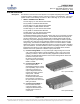
SAG582136600 System Application Guide Spec. No. 582136600 (Model 211NGFB) Issue AU, February 21, 2014 Home SYSTEM OVERVIEW Description: The NetSure™ 211NGFB DC Power System is a complete integrated power system containing rectifiers, intelligent control, metering, monitoring, and distribution. This power system consists of the following mounted in a 1RU or 2RU high by 19” or 23” wide shelf.
SAG582136600 Issue AU, February 21, 2014 • System Application Guide Spec. No. 582136600 (Model 211NGFB) Home ACU+ (Advanced Control Unit Plus) The ACU+ provides Rectifier Module and optional Low Voltage Battery Disconnect (LVBD) or Low Voltage Load Disconnect (LVLD) control, metering functions, monitoring functions, and local/remote alarms as well as PCU control, data acquisition, system alarm management, and advanced battery and energy management.
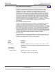
SAG582136600 Issue AU, February 21, 2014 System Application Guide Spec. No. 582136600 (Model 211NGFB) System: Home See the following table. System DC Output Capability 208/240VAC Input 120VAC Input +40°C (+104°F) +65°C (+149°F) +40°C (+104°F) +65°C (+149°F) 500W Rect. 1000W Rect. 500W Rect. 1000W Rect. 500W Rect. 1000W Rect. 500W Rect. 1000W Rect. 58213660001 20.8A 41.6A 12.6A 25A 20.8A 27.4A 12.6A 16.4A 58213660002 31.2A 62.4A 18.9A 37.5A 31.2A 41.1A 18.9A 24.
SAG582136600 Issue AU, February 21, 2014 System Application Guide Spec. No.
SAG582136600 Issue AU, February 21, 2014 System Application Guide Spec. No.
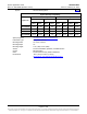
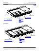
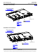
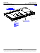
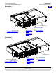
SAG582136600 Issue AU, February 21, 2014 System Application Guide Spec. No. 582136600 (Model 211NGFB) Home 58213660002 with P/N 555261 Rear AC Input Connector (P/O P/N 555261) and AC Input Cables/Line Cords Distribution Unit SCU+ P/N 1M521BNA Rectifier Module (500W) or Rectifier Module (1000W) Page 6 of 105 This document is property of Emerson Network Power, Energy Systems, North America, Inc.
SAG582136600 Issue AU, February 21, 2014 System Application Guide Spec. No.
SAG582136600 Issue AU, February 21, 2014 System Application Guide Spec. No.
SAG582136600 Issue AU, February 21, 2014 System Application Guide Spec. No.
SAG582136600 Issue AU, February 21, 2014 System Application Guide Spec. No. 582136600 (Model 211NGFB) TABLE OF CONTENTS System Overview Picture List Descriptions Accessory Descriptions Specifications Physical Size Information Related Documentation SYSTEM OVERVIEW................................................................................................................................................. 1 58213660001.................................................................................
SAG582136600 Issue AU, February 21, 2014 System Application Guide Spec. No. 582136600 (Model 211NGFB) List LA: Distribution Unit with GMT Fuse Load Distribution Positions, Circuit Breaker Load Distribution Positions, Circuit Breaker Battery Disconnect Positions, and with Low Voltage Load Disconnect (LVLD) .........................................................................................................................................
SAG582136600 Issue AU, February 21, 2014 System Application Guide Spec. No. 582136600 (Model 211NGFB) AC Input Branch Circuit Protection and Wiring .............................................................................................. 64 External Alarm and Monitoring Wiring ........................................................................................................... 64 Load Distribution Wiring (GMT Fuses) (Lists BG and NG only) ........................................................
SAG582136600 Issue AU, February 21, 2014 System Application Guide Spec. No. 582136600 (Model 211NGFB) Home LIST DESCRIPTIONS List 1: 1RU High by 19” Wide Shelf Features ♦ Consists of a 1RU high by 19” wide shelf. ♦ Two (2) 8 AWG 48” long battery cables are factory connected inside the shelf. These cables are terminated at the customer end in a Red SB50 Anderson battery connector. A mating Anderson battery connector is provided [Housing: Emerson P/N 138922, Anderson Power Products P/N 992G1.
SAG582136600 Issue AU, February 21, 2014 System Application Guide Spec. No. 582136600 (Model 211NGFB) Home List 2: 1RU High by 23” Wide Shelf Features ♦ Consists of a 1RU high by 23” wide shelf. ♦ Two (2) 8 AWG 48” long battery cables are factory connected inside the shelf. These cables are terminated at the customer end in a Red SB50 Anderson battery connector. A mating Anderson battery connector is provided [Housing: Emerson P/N 138922, Anderson Power Products P/N 992G1.
SAG582136600 Issue AU, February 21, 2014 System Application Guide Spec. No. 582136600 (Model 211NGFB) Home List 5: 2RU High by 19” Wide Shelf Features ♦ Consists of a 2RU high by 19” wide shelf. ♦ Mounted to the side of the shelf is an AC input housing with plug-in connectors for two (2) AC input feeds. ♦ Includes the Customer Interface Board that provides additional Relay Outputs and Digital Inputs. ♦ The “Relay Outputs Cable” P/N 541308 (shelf side) is factory connected inside the shelf.
SAG582136600 Issue AU, February 21, 2014 System Application Guide Spec. No. 582136600 (Model 211NGFB) Home List 6: 2RU High by 23” Wide Shelf Features ♦ Consists of a 2RU high by 23” wide shelf. ♦ Mounted to the side of the shelf is an AC input housing with plug-in connectors for two (2) AC input feeds. ♦ Includes the Customer Interface Board that provides additional Relay Outputs and Digital Inputs. ♦ The “Relay Outputs Cable” P/N 541308 (shelf side) is factory connected inside the shelf.
SAG582136600 Issue AU, February 21, 2014 System Application Guide Spec. No. 582136600 (Model 211NGFB) Home Rectifier Module (500W), P/N 1R48500 Features Provides one (1) Model R48-500, Spec. No. 1R48500, 500 watt / 48 volt Rectifier Module. Restrictions Each List 1 Shelf holds up to two (2) Rectifier Modules. Each List 2 Shelf holds up to three (3) Rectifier Modules. Each List 5 Shelf holds up to four (4) Rectifier Modules. Each List 6 Shelf holds up to six (6) Rectifier Modules.
SAG582136600 Issue AU, February 21, 2014 System Application Guide Spec. No. 582136600 (Model 211NGFB) SCU+ (Standard Control Unit Plus), P/N 1M521BNA Home Features ♦ Provides the SCU+ Controller. ♦ Factory programmed with the configuration file specified when ordered. Restrictions Each shelf must contain one (1) SCU+ or one (1) ACU+ Controller. Ordering Notes 1) Order one (1) SCU+ Controller (P/N 1M521BNA) or one (1) ACU+ (P/N 1M820BNA) for each shelf.
SAG582136600 Issue AU, February 21, 2014 System Application Guide Spec. No. 582136600 (Model 211NGFB) List 62: Five (5) Load Lead Assemblies (P/N 540988) for 15A GMT Fuse Positions Features Home Provides 12’ long, 14 AWG, load and load return leads that are terminated on one end with the appropriate mating connector to plug into the system’s 15A GMT fuse connector on a List BF, LF, or NF Distribution Unit, and are left un-terminated at the remaining end for connection into customer loads.
SAG582136600 Issue AU, February 21, 2014 System Application Guide Spec. No. 582136600 (Model 211NGFB) List 71: Optional External Battery Cable Assembly with Anderson Connector for (1) Battery String, P/N 545493 Features ♦ Home Provides two (2) 6’ long, 8 AWG, battery cables terminated in a Red SB50 Anderson connector for connecting one (1) battery string to the system.
SAG582136600 Issue AU, February 21, 2014 System Application Guide Spec. No. 582136600 (Model 211NGFB) List 89: Relay Rack Earthquake Anchor Kit, P/N P0987167 Features Home ♦ Provides four (4) sets of hardware for anchoring the relay rack to the floor. Ordering Notes 1) Order as required. List 90: Optional Temperature Probe, P/N 04118246 (shelf side half) and P/N 04118247 (probe side half, 9 ft. long) Features ♦ Up to two (2) temperature probes can be connected to the Customer Interface (IB2) Board.
SAG582136600 Issue AU, February 21, 2014 System Application Guide Spec. No. 582136600 (Model 211NGFB) 2) For a Temperature Probe with a shorter cable see List 90. Home List 93: Battery Tray for 23” Relay Rack Features ♦ Provides one battery tray that mounts four (4) 12V front terminal Valve Regulated Lead Acid (VRLA) batteries. Batteries are configured as one (1) 48V string. ♦ Accepts various VRLA batteries. See Ordering Notes below.
SAG582136600 Issue AU, February 21, 2014 System Application Guide Spec. No. 582136600 (Model 211NGFB) Home Battery Tray P/N 528496 Emerson Network Power P/N Rated 8-Hr. Capacity (Ah) Dimension WxLxH (Inches) Required Tray Spacing Weight (per battery) (lbs) Manufacturer* Model GNB Marathon M12V125FT -- 125 4.90 X 22.00 X 11.15 7U 105 GNB Marathon M12V155FT 112795 155 4.90 X 22.00 X 11.15 7U 119 Northstar NSB110FT -- 110 4.92 X 22.05 X 8.94 7U 91 Northstar NSB170FT -- 167 4.
SAG582136600 Issue AU, February 21, 2014 System Application Guide Spec. No. 582136600 (Model 211NGFB) Home Battery Lug Kit Part Number (Kit provides two lugs for one tray.
SAG582136600 Issue AU, February 21, 2014 System Application Guide Spec. No. 582136600 (Model 211NGFB) Home List 94: Battery Tray for 19” Relay Rack Features ♦ Provides one battery tray that mounts four (4) 12V front terminal Valve Regulated Lead Acid (VRLA) batteries. Batteries are configured as one (1) 48V string. ♦ Accepts various VRLA batteries. See Ordering Notes below.
SAG582136600 Issue AU, February 21, 2014 System Application Guide Spec. No. 582136600 (Model 211NGFB) Home Battery Tray P/N 558047 Model Emerson Network Power P/N Northstar NSB90FT -- 90 4.25 X 15.59 X 10.04 7U 71 Northstar NSB100FT -- 100 4.25 X 15.59 X 11.03 7U 78 GNB Marathon M12V90FT -- 90 4.13 X 15.55 X 10.63 7U 70 Enersys 12TD100F4 -- 96 4.3 X 15.5 X 11.3 8U 71 Manufacturer* Rated 8-Hr.
SAG582136600 Issue AU, February 21, 2014 System Application Guide Spec. No. 582136600 (Model 211NGFB) Home Battery Tray P/N 548213 Rated 8-Hr. Capacit y (Ah) Dimension WxLxH (Inches) Required Tray Spacing Weight (per battery) (lbs) Manufacturer* Model Emerson Network Power P/N Enersys 12V125F 122009 125 4.10 X 22.10 X 12.40 8U 124 Enersys 12TD150F -- 143 4.3 X 21.7 X 11.3 8U 105 * See Battery Manufacturer Information located at the end of this document.
SAG582136600 Issue AU, February 21, 2014 System Application Guide Spec. No. 582136600 (Model 211NGFB) Home Ampere Rating Part No., Circuit Breaker, 1 Electrical/Mechanical Trip (Black Handle) 1 256690300 3 256690700 5 256691100 10 256691500 15 256691900 20 256692300 25 256692700 30 256693100 35 256693500 40 256693900 50 256694300 60 256694700 70 256695100 75 256695500 100 256695900 Part No., Left-Side Breaker Mtg. Kit (For Reference Only) Part No., Right-Side Breaker Mtg.
SAG582136600 Issue AU, February 21, 2014 System Application Guide Spec. No. 582136600 (Model 211NGFB) List BF: Distribution Unit with GMT Fuse Load Distribution Positions and with Low Voltage Battery Disconnect (LVBD) Features ♦ Provides a Distribution Unit with Low Voltage Battery Disconnect (LVBD), a battery shunt, (3) battery connection points, and thirteen (13) GMT fuse load distribution positions. ♦ Five (5) 0A to 15A GMT fuse load distribution positions.
SAG582136600 Issue AU, February 21, 2014 System Application Guide Spec. No. 582136600 (Model 211NGFB) List LF: Distribution Unit with GMT Fuse Load Distribution Positions Home and with Low Voltage Load Disconnect (LVLD) Features ♦ Provides a Distribution Unit with Low Voltage Load Disconnect (LVLD), a battery shunt, (3) battery connection points, and thirteen (13) GMT fuse load distribution positions. ♦ Five (5) 0A to 15A GMT fuse load distribution positions.
SAG582136600 Issue AU, February 21, 2014 System Application Guide Spec. No. 582136600 (Model 211NGFB) List NF: Distribution Unit with GMT Fuse Load Distribution Positions Home and w/out Low Voltage Disconnect Features ♦ Provides a Distribution Unit w/out low voltage disconnect, a battery shunt, (3) battery connection points, and thirteen (13) GMT fuse load distribution positions. ♦ Five (5) 0A to 15A GMT fuse load distribution positions. Eight (8) 0A to 10A GMT fuse load distribution positions.
SAG582136600 Issue AU, February 21, 2014 System Application Guide Spec. No.
SAG582136600 Issue AU, February 21, 2014 System Application Guide Spec. No.
SAG582136600 Issue AU, February 21, 2014 System Application Guide Spec. No. 582136600 (Model 211NGFB) List NC: Distribution Unit with GMT Fuse Load Distribution Positions, Circuit Breaker Load Distribution Positions, and w/out Low Voltage Disconnect Features ♦ Home Provides a Distribution Unit w/out low voltage disconnect, a battery shunt, (3) battery connection points, four (4) bullet nose-type circuit breaker load distribution positions, five (5) GMT fuse load distribution positions.
SAG582136600 Issue AU, February 21, 2014 System Application Guide Spec. No.
SAG582136600 Issue AU, February 21, 2014 System Application Guide Spec. No.
SAG582136600 Issue AU, February 21, 2014 System Application Guide Spec. No.
SAG582136600 Issue AU, February 21, 2014 System Application Guide Spec. No. 582136600 (Model 211NGFB) List BG: Distribution Unit with GMT Fuse Load Distribution Positions and with Low Voltage Battery Disconnect (LVBD) Features ♦ Provides a Distribution Unit with Low Voltage Battery Disconnect (LVBD), battery cables, and ten (10) GMT fuse load distribution positions (15A maximum). ♦ Two (2) 8 AWG 48” long battery cables are factory connected inside the shelf.
SAG582136600 Issue AU, February 21, 2014 System Application Guide Spec. No. 582136600 (Model 211NGFB) List NG: Distribution Unit with GMT Fuse Load Distribution Positions and w/out Low Voltage Disconnect Features ♦ Provides a Distribution Unit w/out low voltage disconnect, a battery shunt, battery cables, and ten (10) GMT fuse load distribution positions (15A maximum). ♦ Two (2) 8 AWG 48” long battery cables are factory connected inside the shelf.
SAG582136600 Issue AU, February 21, 2014 System Application Guide Spec. No. 582136600 (Model 211NGFB) List KG: Distribution Panel with (20) GMT Fuse Load Distribution Positions Features ♦ Home 1U-high GMT fuse panel that provides Single Load Distribution (-48V) Provides twenty (20) 0A to 15A GMT fuse load distribution positions. Caution: At +40°C and +65°C ambient, a fuse with a rating of greater than 10 amperes SHALL HAVE an empty mounting position between it and any other fuse.
SAG582136600 Issue AU, February 21, 2014 System Application Guide Spec. No. 582136600 (Model 211NGFB) Home ACCESSORY DESCRIPTIONS Relay Racks Features ♦ The following relay racks are available. Restrictions Customer must mount Power/Distribution Shelf in relay rack. If battery trays are ordered, they are factory mounted in the relay rack. Ordering Notes 1) Order from relay racks listed in Table 1.
SAG582136600 Issue AU, February 21, 2014 System Application Guide Spec. No. 582136600 (Model 211NGFB) Home Mounting and Adapter Kits Optional Wall Mount Bracket Kit for Lists 1 and 2, P/N 541285 Features ♦ Allows for horizontal or vertical wall mounting. ♦ See Physical Size Information for mounting dimensions. Restrictions For use with List 1 or 2 only. Customer must supply mounting fasteners for securing the Wall Mount Bracket to the wall.
SAG582136600 Issue AU, February 21, 2014 System Application Guide Spec. No. 582136600 (Model 211NGFB) Home Optional 19” Rear Cover Kit, P/N 555260 Features ♦ Allows for 19” 1RU flush rack mount configuration ♦ AC input unit is moved to the rear panel Restrictions For use with List 1 only. Ordering Notes 1) Order P/N 555260, which consists of one (1) P/N 553271 19” rear cover assembly, one (1) P/N 29041838 caution label and one (1) P/N PSK04118562 AC input jumper.
SAG582136600 Issue AU, February 21, 2014 System Application Guide Spec. No. 582136600 (Model 211NGFB) Home Distribution Devices GMT Load Distribution Fuses Features ♦ Each List BF, LF, NF Distribution Unit holds up to five (5) 0-15A GMT load distribution fuses and eight (8) 0-10A GMT load distribution fuses. ♦ Each List BC, LC, NC, BA, LA, NA Distribution Unit holds up to five (5) 0-10A GMT load distribution fuses.
SAG582136600 Issue AU, February 21, 2014 System Application Guide Spec. No. 582136600 (Model 211NGFB) Home Bullet Nose-Type Circuit Breakers Features ♦ Each List BC, LC, and NC Distribution Unit holds up to four (4) bullet nose-type load distribution circuit breakers. Each List BA, LA, and NA Distribution Unit holds up to two (2) bullet nose-type battery disconnect circuit breakers and up to two (2) bullet nose-type load distribution circuit breakers.
SAG582136600 Issue AU, February 21, 2014 System Application Guide Spec. No. 582136600 (Model 211NGFB) Optional Bullet Nose 6-Position GMT Fuse Module, P/N 545332 Features ♦ Factory installed in a List BC, LC, NC, BA, LA, and NA Distribution Unit. ♦ Provides six (6) 0A to 15A GMT fuse load distribution positions. ♦ Screw clamp type load and load return terminals provided. Home Includes six (6) dummy fuses equipped with safety fuse covers. Restrictions For use with Lists BC, LC, NC, BA, LA, and NA.
SAG582136600 Issue AU, February 21, 2014 System Application Guide Spec. No. 582136600 (Model 211NGFB) Home AC Input Cables and Line Cords AC Input Cable Assembly, P/N 535232 Features ♦ Provides one (1) 30” long, 8 AWG, AC Input Cable Assembly; ♦ terminated on one end with a Molex plug which mates with AC input receptacle on the Power/Distribution Shelf, ♦ and the remaining end un-terminated. Restrictions Rated for 30A. For use with List 1, 2, 5, and 6.
SAG582136600 Issue AU, February 21, 2014 System Application Guide Spec. No. 582136600 (Model 211NGFB) Home AC Input Line Cord, 208/240VAC, P/N 545616 Features ♦ Provides one (1) 6’ long, 8 AWG, AC Input Line Cord; ♦ terminated on one end with a Molex plug which mates with AC input receptacle on the Power/Distribution Shelf, ♦ and on the remaining end with a NEMA L6-30P twist-lock plug. Restrictions For 208/240 VAC only (rated for 30A at 208/240VAC). For use with List 1, 2, 5, and 6.
SAG582136600 Issue AU, February 21, 2014 System Application Guide Spec. No. 582136600 (Model 211NGFB) Home AC Input Line Cord, 120VAC, P/N 545478 Features ♦ Provides one (1) 14’ long, 14/3 AWG, AC Input Line Cord; ♦ terminated on one end with a Molex plug which mates with AC input receptacle on the Power/Distribution Shelf, ♦ and on the remaining end with a NEMA 5-15P plug. Restrictions For 120 VAC only (rated for 15A at 120VAC). For use with List 1 and 5 equipped with R48-500 Rectifier Modules.
SAG582136600 Issue AU, February 21, 2014 System Application Guide Spec. No. 582136600 (Model 211NGFB) Home AC Input Line Cord, 208/240VAC, P/N 545480 Features ♦ Provides one (1) 14’ long, 14/3 AWG, AC Input Line Cord; ♦ terminated on one end with a Molex plug which mates with AC input receptacle on the Power/Distribution Shelf, ♦ and on the remaining end with a NEMA L6-15P twist-lock plug. Restrictions For 240 VAC only (rated for 15A at 208/240VAC). For use with List 1 and 5.
SAG582136600 Issue AU, February 21, 2014 System Application Guide Spec. No. 582136600 (Model 211NGFB) Home AC Input Line Cord, 208/240VAC, P/N 545553 Features ♦ Provides one (1) 14’ long, 12/3 AWG, AC Input Line Cord; ♦ terminated on one end with a Molex plug which mates with AC input receptacle on the Power/Distribution Shelf, ♦ and on the remaining end with a NEMA L6-20P twist-lock plug. Restrictions For 240 VAC only (rated for 20A at 208/240VAC). For use with List 1, 2, 5, and 6.
SAG582136600 Issue AU, February 21, 2014 System Application Guide Spec. No. 582136600 (Model 211NGFB) Home AC Input Line Cord, 120VAC, P/N 548457 Features ♦ Provides one (1) 6’ long, 14/3 AWG, AC Input Line Cord; ♦ terminated on one end with a Molex plug which mates with AC input receptacle on the Power/Distribution Shelf, ♦ and on the remaining end with a NEMA 5-15P plug. Restrictions For 120 VAC only (rated for 15A at 120VAC). For use with List 1 and 5 with R48-500 Rectifiers.
SAG582136600 Issue AU, February 21, 2014 System Application Guide Spec. No. 582136600 (Model 211NGFB) Special Application Digital Input Cable Kit, P/N 554935 Home Features ♦ Provides an alarm cable kit to add -48VDC to digital input #2. The kit consists of two pieces that plug together to make a complete connection. One part is pre-wired to the shelf and the other part is shipped loose. Restrictions For use with List 1 and 2.
SAG582136600 Issue AU, February 21, 2014 System Application Guide Spec. No. 582136600 (Model 211NGFB) Home ORDERING CODE DESCRIPTION P7000858 Cable assy for one SLC96 channel bank (8 ft.) P7001139 Cable assy for one SLC96 channel bank (20 ft.) P7000859 Cable assy for one SLC5 channel bank (8 ft.) P7001136 Cable assy for one SLC5 channel bank (20 ft.) P7000937* Cable assy for one channel bank, generic applications (8 ft.
SAG582136600 Issue AU, February 21, 2014 System Application Guide Spec. No. 582136600 (Model 211NGFB) Home External Battery Disconnect Unit, P/N 535282 Features ♦ Battery Disconnect Unit with mounting tabs. ♦ Two 1/4-20 studs w/hardware provided for installation of single hole battery lugs. ♦ One (10’ long) alarm lead provided. Restrictions Circuit breakers are ordered separately. Maximum number of Battery Disconnect Units per system is three (3). Ordering Notes 1) Order by P/N 535282 as required.
SAG582136600 Issue AU, February 21, 2014 System Application Guide Spec. No. 582136600 (Model 211NGFB) Home NetSure™ 211BC Battery Cabinet (Spec. No. 541434) Features ♦ The NetSure™ 211BC Battery Cabinet is rated at 30 amperes, and can be mounted in a 19” or 23” nominal relay rack, or mounted to a suitable wall. ♦ The Battery Cabinet contains one (1) 40 ampere battery disconnect circuit breaker. ♦ Battery circuit breaker alarm leads are provided to tie into the power system’s alarm circuit.
SAG582136600 Issue AU, February 21, 2014 System Application Guide Spec. No. 582136600 (Model 211NGFB) Home NetSure™ 211BC Battery Cabinet (Spec. No. 545534) Features ♦ The NetSure™ 211BC Battery Cabinet is rated at 30 amperes, and can be mounted in a 19” or 23” nominal relay rack, or mounted to a suitable wall. ♦ The Battery Cabinet contains one (1) 40 ampere battery disconnect circuit breaker. ♦ Battery circuit breaker alarm leads are provided to tie into the power system’s alarm circuit.
SAG582136600 Issue AU, February 21, 2014 System Application Guide Spec. No. 582136600 (Model 211NGFB) Home NetSure™ 211BC Battery Cabinet (Spec. No. 545506) Features ♦ The NetSure™ 211BC Battery Cabinet is rated at 30 amperes, and can be mounted in a 23” nominal relay rack, or mounted to a suitable wall. ♦ The Battery Cabinet contains one (1) 40 ampere battery disconnect circuit breaker. ♦ Battery circuit breaker alarm leads are provided to tie into the power system’s alarm circuit.
SAG582136600 Issue AU, February 21, 2014 System Application Guide Spec. No. 582136600 (Model 211NGFB) Home NetSure™ 211BC Battery Cabinet (Spec. No. 554631) Features ♦ The NetSure™ 211BC Battery Cabinet is rated at 30 amperes, and can be mounted in a 19” or 23” nominal relay rack, or mounted to a suitable wall. ♦ The Battery Cabinet contains one (1) 40 ampere battery disconnect circuit breaker. ♦ Battery circuit breaker alarm leads are provided to tie into the power system’s alarm circuit.
SAG582136600 Issue AU, February 21, 2014 System Application Guide Spec. No. 582136600 (Model 211NGFB) SM TEMP Temperature Concentrator (P/N 547490) Home Features ♦ Allows for multiple temperature probes to be used for temperature compensation. Compensation can be based on highest probe temperature or average probe temperature. ♦ Provides (8) temperature probe inputs per SM TEMP. ♦ Can be cascaded up to (8) SM TEMP modules, connecting up to 64 temperature probes.
SAG582136600 Issue AU, February 21, 2014 System Application Guide Spec. No. 582136600 (Model 211NGFB) Home Anderson Battery Connector Features Includes the components necessary to assemble an Anderson connector onto a battery cable. Restrictions Appropriate battery post mating lugs must be ordered separately. Ordering Notes Order Anderson connector housings and lugs per the following table.
SAG582136600 Issue AU, February 21, 2014 System Application Guide Spec. No. 582136600 (Model 211NGFB) Home Digital Input and Relay Output Cables Features ♦ Lists 1 and 2: Two sets of customer wiring cables are available. One set is for Digital Inputs and Relay outputs. The other set is for an additional -48V digital input. One half of the Digital Inputs and Relay Outputs cable is provided and factory connected in the shelf.
SAG582136600 Issue AU, February 21, 2014 System Application Guide Spec. No. 582136600 (Model 211NGFB) Home Replacement Modules Ordering Notes 1) Refer to Table 5. Item Part Number 500W Rectifier Module 1R48500 1000W Rectifier Module 1R481000 Rectifier Module Fan 32010093 SCU+ Controller Module 1M521BNA* * Also specify the appropriate SCU+ configuration file. Refer to the configuration file label on your existing SCU+ Controller.
SAG582136600 Issue AU, February 21, 2014 System Application Guide Spec. No. 582136600 (Model 211NGFB) Home Wiring Notes Refer also to the next section, Wiring Illustrations. Shelf Frame Grounding Stud Features ♦ An M5 frame grounding stud with hardware is provided on the rear of the shelf. Restrictions Recommended frame ground wire size is 6 AWG. AC Input Branch Circuit Protection and Wiring Features ♦ Each shelf contains one (1) or two (2) side mounted plug-in AC input connector(s).
SAG582136600 Issue AU, February 21, 2014 System Application Guide Spec. No. 582136600 (Model 211NGFB) Home factory connected to these terminals. The other half (includes mating connector on one end and un-terminated on the other end) is ordered separately. If an additional -48V Digital Input cable is ordered, one half of the cable is factory connected in the shelf. The other half includes mating connector on one end and is un-terminated on the other end.
SAG582136600 Issue AU, February 21, 2014 System Application Guide Spec. No. 582136600 (Model 211NGFB) Load Distribution Wiring (GMT Fuses) (Lists BC, LC, NC, BA, LA, and NA) Features Home Load distribution (GMT fuses) and load return leads are connected to receptacles located inside the Distribution Unit. Load leads are brought into the right side (as viewed from the front) of the shelf and are accessible from the front of the shelf.
SAG582136600 Issue AU, February 21, 2014 System Application Guide Spec. No.
SAG582136600 Issue AU, February 21, 2014 System Application Guide Spec. No. 582136600 (Model 211NGFB) Load Distribution Wiring (GMT Fuses) (List KG) Features Home Load distribution (GMT fuses) and load return leads are connected to terminal blocks located on the front of the assembly. Restrictions The rating of the distribution device determines the wire size requirements.
SAG582136600 Issue AU, February 21, 2014 System Application Guide Spec. No. 582136600 (Model 211NGFB) Ordering Notes 1) The rating of the distribution device determines the wire size requirements. For wire size and lug selection, refer to Table 6. 2) For other available lugs, refer to drawings 031110100 through 031110300.
SAG582136600 Issue AU, February 21, 2014 System Application Guide Spec. No. 582136600 (Model 211NGFB) Home Wiring Illustrations Shelf Frame Grounding Stud (both 1U and 2U Panels, List 1 and 5 shown) Page 70 of 105 This document is property of Emerson Network Power, Energy Systems, North America, Inc. and contains confidential and proprietary information owned by Emerson Network Power, Energy Systems, North America, Inc.
SAG582136600 Issue AU, February 21, 2014 System Application Guide Spec. No. 582136600 (Model 211NGFB) Home AC Input Wiring (Lists 1 and 2) List 1 and List 2 with Side AC Input Connectors (List 1 shown) List 1 and List 2 with Rear AC Input Connectors (List 2 shown) Front Rear * Rectifiers are numbered left to right as viewed from the front. AC input connections are made using the supplied AC input cable assemblies/ line cords connected here.
SAG582136600 Issue AU, February 21, 2014 System Application Guide Spec. No. 582136600 (Model 211NGFB) Home AC Input Wiring (Lists 5 and 6) List 5 List 6 Front Front 4 AC input connections are made using the supplied AC input cable assemblies/ line cords connected here. 2 3 1 AC input connections are made using the supplied AC input cable assemblies/ line cords connected here.
SAG582136600 Issue AU, February 21, 2014 System Application Guide Spec. No. 582136600 (Model 211NGFB) Home External Alarm and Monitoring Wiring (Lists 1 and 2) SCU+ Controller Notes Relay Output/Digital Input Cable P/N 545494 is factory connected to terminals. Mating half (w/ unterminated ends) available, P/N 545495. When an additional -48V Digital Input Cable Kit P/N 554935 is ordered, one half of the kit is factory connected in the shelf.
SAG582136600 Issue AU, February 21, 2014 System Application Guide Spec. No. 582136600 (Model 211NGFB) Home External Alarm and Monitoring Wiring (Lists 5 and 6) Note: A custom digital input cable and internal wiring kit is available, P/N 545594. This kit is factory installed only. Notes Relay Output Cable P/N 541308 is factory connected to Relay Output terminals. Mating half (w/ unterminated ends) available, P/N 541309.
SAG582136600 Issue AU, February 21, 2014 System Application Guide Spec. No. 582136600 (Model 211NGFB) Yellow Alarm Lead (P/N 535294) (factory wired to circuit breaker alarm terminal) Alarm Wiring to a Single External Battery Disconnect Unit Torque to 84 in-lbs using supplied hardware Procedure 1. Connect YELLOW lead exiting top of Battery Disconnect Unit per table below. Remove quick connect terminal first.
SAG582136600 Issue AU, February 21, 2014 System Application Guide Spec. No. 582136600 (Model 211NGFB) Yellow Jumper/Alarm Lead (P/N 524384) (Ordered separately and supplied loose. Must be wired by the customer to each circuit breaker “C (Common)” alarm terminal) Yellow Alarm Lead (P/N 535294) (factory wired to circuit breaker alarm terminal) * No terminal on 524384 jumper Connect to shelf per table below. see previous page REMOVE COMPLETELY FROM ALL BATTERY DISCONNECT UNITS AND DISCARD.
SAG582136600 Issue AU, February 21, 2014 System Application Guide Spec. No. 582136600 (Model 211NGFB) Home Yellow Jumper/Alarm Lead (P/N 524384) (Ordered separately and supplied loose. Must be wired by the customer to each circuit breaker “C (Common)” alarm terminal) * No terminal on 524384 jumper Connect to shelf per table below. see previous page see previous page see previous page 1st BATTERY TRAY BATTERY DISCONNECT CIRCUIT BREAKER (Side cover removed in illustration to show wiring details.
SAG582136600 Issue AU, February 21, 2014 System Application Guide Spec. No. 582136600 (Model 211NGFB) Home Yellow Jumper/Alarm Lead (P/O Cabinet) Orange Wire on 541434 not used Connect to shelf per table below. alarm wire alarm wire 1st BATTERY CABINET BATTERY DISCONNECT CIRCUIT BREAKER alarm wire 2nd BATTERY CABINET BATTERY DISCONNECT CIRCUIT BREAKER Alarm Wiring to Battery Cabinets 3rd BATTERY CABINET BATTERY DISCONNECT CIRCUIT BREAKER Procedure 1.
SAG582136600 Issue AU, February 21, 2014 System Application Guide Spec. No. 582136600 (Model 211NGFB) Load Distribution Wiring (GMT Fuses) (Lists BG and NG installed in a List 1 or 2, List 1 shown) Home Connect to Front Terminal Block Load Return Leads -48V Distribution Leads Terminal Fuse Position Load Return Load (-48V) 1 2 3 4 5 6 7 8 9 10 1 3 5 7 9 11 13 15 17 19 2 4 6 8 10 12 14 16 18 20 Page 79 of 105 This document is property of Emerson Network Power, Energy Systems, North America, Inc.
SAG582136600 Issue AU, February 21, 2014 System Application Guide Spec. No. 582136600 (Model 211NGFB) Load Distribution Wiring (GMT Fuses) (Lists BF, LF, and NF installed in a List 5 or 6, List 5 shown) Home Front Load Distribution Leads Enter Here GMT Fuse Positions (Max. 15A) GMT Fuse Load Distribution Leads Connect Here Mating Connectors and 12' Leads provided with List 62. -48V on Left (Black Lead), Return on Right (White Lead) GMT Fuse Positions (Max.
SAG582136600 Issue AU, February 21, 2014 System Application Guide Spec. No. 582136600 (Model 211NGFB) Load Distribution Wiring (GMT Fuses) (Lists BC, LC, NC, BA, LA, and NA installed in a List 5 or 6, List 5 shown) Home Front Load Distribution Leads Enter Here GMT Fuse Positions GMT Fuse Load Distribution Leads Connect Here Mating Connectors and 12' Leads provided with List 60. -48V on Left (Black Lead), Return on Right (White Lead); as viewed from side with door closed.
SAG582136600 Issue AU, February 21, 2014 System Application Guide Spec. No. 582136600 (Model 211NGFB) Load Distribution Wiring (Optional Bullet Nose 6-Position GMT Fuse Module) -48V Distribution Leads Home Load Return Leads Page 82 of 105 This document is property of Emerson Network Power, Energy Systems, North America, Inc. and contains confidential and proprietary information owned by Emerson Network Power, Energy Systems, North America, Inc.
SAG582136600 Issue AU, February 21, 2014 System Application Guide Spec. No. 582136600 (Model 211NGFB) Load Distribution Wiring (Circuit Breakers) and CO Ground Wiring (Lists BC, LC, and NC installed in a List 5 or 6, List 5 shown) Home Front Circuit Breaker Load Distribution and CO Ground Leads Enter Here Load Distribution Circuit Breakers Front Portion of shelf removed in illustration for clarity. Leads are brought into side of shelf, and tools to secure lugs from front of shelf.
SAG582136600 Issue AU, February 21, 2014 System Application Guide Spec. No. 582136600 (Model 211NGFB) Home Load Distribution Wiring (Circuit Breakers), Input Battery Wiring (Circuit Breakers), and CO Ground Wiring (Lists BA, LA, and NA installed in a List 5 or 6, List 5 shown) Front CO Ground, Circuit Breaker Load Distribution, and Circuit Breaker Battery Leads Enter Here Load Distribution Circuit Breakers Battery Disconnect Circuit Breakers Front Portion of shelf removed in illustration for clarity.
SAG582136600 Issue AU, February 21, 2014 System Application Guide Spec. No. 582136600 (Model 211NGFB) Home “B” Side Loads #6 - #10 Connections are made to screw compression terminal blocks. Wire size range is 26 to 14 AWG. “B” Side Returns Inputs for Side “A” and Side “B” are strapped in this system.
SAG582136600 Issue AU, February 21, 2014 System Application Guide Spec. No. 582136600 (Model 211NGFB) Input Battery Wiring (Lists BG and NG installed in a List 1 or 2, List 1 shown) Home Page 86 of 105 This document is property of Emerson Network Power, Energy Systems, North America, Inc. and contains confidential and proprietary information owned by Emerson Network Power, Energy Systems, North America, Inc.
SAG582136600 Issue AU, February 21, 2014 System Application Guide Spec. No. 582136600 (Model 211NGFB) Input Battery Wiring (Lists BF, LF, NF, BC, LC, and NC installed in a List 1 or 5, List 5 shown) and CO Ground Wiring (Lists BF, LF, and NF installed in a List 1 or 5, List 5 shown) Home List NF Distribution Unit shown. List BF, LF, BC, LC, and NC similar.
SAG582136600 Issue AU, February 21, 2014 System Application Guide Spec. No. 582136600 (Model 211NGFB) Home SPECIFICATIONS Note: For all rectifier specifications, refer to the separate Rectifier User Manual (UM1R48500/UM1R481000) supplied with your Power System. For all controller specifications, refer to the Controller User Manual (UM1M521B or UM1M820B) supplied with your Power System.
SAG582136600 Issue AU, February 21, 2014 System Application Guide Spec. No. 582136600 (Model 211NGFB) 1.2.3 EMC and Safety: (A) Complies with the Low-Voltage Directive, 73/23/EEC. Complies with Emissions and Immunity requirements as specified in GR-1089-Core Issue 4. Home EMC Emissions EN 55022: 1998 CFR 47 – Part 15 GR-1089 Issue 4 Test Level Conducted Class B Radiated Class B Immunity GR-1089 Issue 4 EN 61000-4-2 Electrostatic Discharge 8kV / 15kV EN 61000-4-4 Electric Fast Transients 0.
SAG582136600 Issue AU, February 21, 2014 1.3.4 1.3.5 System Application Guide Spec. No. 582136600 (Model 211NGFB) Load distribution (GMT fuses) and load return leads are connected to receptacles located inside the Distribution Unit. Load leads are brought into the right side (as viewed from the front) of the shelf and are accessible from the front of the shelf. Alarm and Monitoring Connections: Customer wiring cables are available.
SAG582136600 Issue AU, February 21, 2014 System Application Guide Spec. No. 582136600 (Model 211NGFB) Home PHYSICAL SIZE INFORMATION Overall Dimensions – List 1 Top View Left Side View 17.3 18.3 19.0 5 0.5 12 Right Side View Front View 1.25 Rear View Bottom View 1.72 0.23 Notes: 1. All dimensions are in inches, unless otherwise specified. 2. Weight in LBS. Net: 16 Shipping: 3. Finish: Front Panels are Gray Shelf is Galvaneal.
SAG582136600 Issue AU, February 21, 2014 System Application Guide Spec. No. 582136600 (Model 211NGFB) Home Additional Dimensions – List 1 with Wall Mounting Kit (P/N 541285) Horizontal Wall Mounting 19.45 18.72 15.34 Top View 0.90 Rear View Note: All dimensions are in inches. Vertical Wall Mounting 1.15 18.38 19.87 Top View 2.65 Right Side View Page 92 of 105 This document is property of Emerson Network Power, Energy Systems, North America, Inc.
SAG582136600 Issue AU, February 21, 2014 System Application Guide Spec. No. 582136600 (Model 211NGFB) Additional Dimensions – List 1 with Optional 19” Rear Cover Kit, P/N 555260 Home 0.6 Top View 16.9 18.3 19.0 12.0 0.5 Right Side View Front View 1.25 1.75 Rear View 0.25 Page 93 of 105 This document is property of Emerson Network Power, Energy Systems, North America, Inc. and contains confidential and proprietary information owned by Emerson Network Power, Energy Systems, North America, Inc.
SAG582136600 Issue AU, February 21, 2014 System Application Guide Spec. No. 582136600 (Model 211NGFB) Additional Dimensions – List 1 with Optional 3” Projection Mount Kit, P/N 556828 Home Rear View 12 3 Left Side View Top View 0.5 Right Side View 1.25 1.71 0.24 16.9 18.3 19.0 Front View Page 94 of 105 This document is property of Emerson Network Power, Energy Systems, North America, Inc.
SAG582136600 Issue AU, February 21, 2014 System Application Guide Spec. No. 582136600 (Model 211NGFB) Home Overall Dimensions – List 2 Page 95 of 105 This document is property of Emerson Network Power, Energy Systems, North America, Inc. and contains confidential and proprietary information owned by Emerson Network Power, Energy Systems, North America, Inc. Any copying, use, or disclosure of it without the written permission of Emerson Network Power, Energy Systems, North America, Inc.
SAG582136600 Issue AU, February 21, 2014 System Application Guide Spec. No. 582136600 (Model 211NGFB) Home Additional Dimensions – List 2 with Wall Mounting Kit (P/N 541285) Horizontal Wall Mounting 23.41 22.69 15.34 Top View 0.90 Rear View Note: All dimensions are in inches. Vertical Wall Mounting 1.15 22.34 2.65 23.83 Top View Right Side View Page 96 of 105 This document is property of Emerson Network Power, Energy Systems, North America, Inc.
SAG582136600 Issue AU, February 21, 2014 System Application Guide Spec. No. 582136600 (Model 211NGFB) Additional Dimensions – List 2 with Optional 23” Rear Cover Kit, P/N 555261 Home 0.6 Top View 20.8 22.3 23.0 0.5 12.0 Right Side View 1.25 Front View Rear View 1.75 0.25 Page 97 of 105 This document is property of Emerson Network Power, Energy Systems, North America, Inc. and contains confidential and proprietary information owned by Emerson Network Power, Energy Systems, North America, Inc.
SAG582136600 Issue AU, February 21, 2014 System Application Guide Spec. No. 582136600 (Model 211NGFB) Home Overall Dimensions – List 5 Top View Left Side View 17.3 18.3 19.0 19.4 Front View 5 0.5 Right Side View 3.00 Rear View Bottom View 12 3.46 0.23 Notes: 1. All dimensions are in inches, unless otherwise specified. 2. Weight in LBS. Net: 30 Shipping: 3. Finish: Front Panels are Gray Shelf is Galvaneal.
SAG582136600 Issue AU, February 21, 2014 System Application Guide Spec. No. 582136600 (Model 211NGFB) Home Overall Dimensions – List 6 Page 99 of 105 This document is property of Emerson Network Power, Energy Systems, North America, Inc. and contains confidential and proprietary information owned by Emerson Network Power, Energy Systems, North America, Inc. Any copying, use, or disclosure of it without the written permission of Emerson Network Power, Energy Systems, North America, Inc.
SAG582136600 Issue AU, February 21, 2014 System Application Guide Spec. No. 582136600 (Model 211NGFB) Additional Dimensions – Lists 1, 2, 5 and 6 with Wall Mounting Kit (P/N 553203) Home Lists 1 and 2 18.936 (19” Shelf, shown) 22.906 (23” Shelf) 4.625 20.543 (19”, shown Shelf) 24.513 (23” Shelf) Bottom View Right Side View Lists 5 and 6 Note: All dimensions are in inches. 18.936 (19” Shelf, shown) 22.906 (23” Shelf) 4.625 20.543 (19” Shelf, shown) 24.
SAG582136600 Issue AU, February 21, 2014 System Application Guide Spec. No. 582136600 (Model 211NGFB) Home Overall Dimensions – List KG Notes: 1. Dimensions in inches unless otherwise specified. 2. Finish: Gray 3. Weight: Net: Shipping: 8.31 10.00 5.05 See Mounting Angle Detail Top View 0.92 17.25 Left Side View 1.75 Right Side View 18.25 19.25 22.31 23.25 Front View Bottom View R 0.125 (TYP) 0.235 0.125 Mounting Angle Detail 0.500 0.500 0.125 0.235 1.250 1.250 0.125 0.
SAG582136600 Issue AU, February 21, 2014 System Application Guide Spec. No. 582136600 (Model 211NGFB) Home Overall Dimensions – 19” Battery Tray Optional Battery Disconnect Circuit Breakers (Shown on Right Side, Available on Either Side) A See Note 3 10.50 12.25 14.00 (as ordered) ISO View Notes: 1. All dimensions are in inches, unless otherwise specified. 2. P/N 558047 tray shown. P/Ns 541034, 540841 and 548213 similar. 3. Dimension Dimension Tray P/Ns B A 17.60 7.78 558047 20.95 7.03 541034 12.50 6.
SAG582136600 Issue AU, February 21, 2014 System Application Guide Spec. No. 582136600 (Model 211NGFB) Home Overall Dimensions – 23” Battery Tray Optional Battery Disconnect Circuit Breakers (Shown on Right Side, Available on Either Side) A See Note 3 10.50 12.25 14.00 (as ordered) ISO View Front View Notes: 1. All dimensions are in inches, unless otherwise specified. 2. P/N 528496 tray shown. P/N 540842 and 557573 similar. 3. Dimension Dimension Tray P/N A B 528496 9.781 24.437 540842 6.90 12.
SAG582136600 Issue AU, February 21, 2014 System Application Guide Spec. No. 582136600 (Model 211NGFB) BATTERY MANUFACTURER INFORMATION Home Some equipment described in this System Application Guide is designed to accommodate batteries from various manufacturers. The following are referenced in this document. C&D: C&D Technologies, Inc., Powercom Div., 1400 Union Meeting Road, Blue Bell, PA 19422-0858 ® Deka : East Penn Mfg. Co., Inc., Lyon Station, PA 19536-0147 ® Douglas : Douglas Battery Mfg. Co.
SAG582136600 Issue AU, February 21, 2014 System Application Guide Spec. No. 582136600 (Model 211NGFB) Home REVISION RECORD Change Number (ECO) Description of Change Date Approved AN LLP217521 Additional Battery P/N added to Battery Table. Added optional 19” and 23” rear cover kits P/N 555260 and P/N 555261. Added optional digital input cable kit P/N 554935. Added references to List 73 optional external battery cable assembly P/N 555050. Added PCU blank filler as accessory.