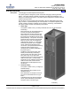
SAG582140001 System Application Guide Spec. No. 582140001 (Model 801NLDB, 801NLEB, 801NL-B) Issue AN, June 4, 2014 Home SYSTEM OVERVIEW Description: -48V DC @ up to 16,800 amperes Power System. This power system is designed to power a load while charging a positive grounded battery. This power system is capable of operating in a batteryless installation or off battery for maintenance purposes. This power system is designed for operation with the positive output grounded.
SAG582140001 Issue AN, June 4, 2014 System Application Guide Spec. No. 582140001 (Model 801NLDB, 801NLEB, 801NL-B) Home fuseholders or Bullet Nose-type circuit breakers. • Rectifier Modules The Rectifier Modules provide load power, battery float current, and battery recharge current during normal operating conditions. • MCA (Meter-Control-Alarm) The MCA controls the operation of the Rectifier Modules and provides power system control, metering, monitoring, and alarm functions.
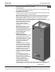
System Application Guide Spec. No. 582140001 (Model 801NLDB, 801NLEB, 801NL-B) SAG582140001 Issue AN, June 4, 2014 Home provided to monitor equipment external to the power system. The LMS input circuit cards monitor a variety of analog, binary, and temperature points external to the system. An LMS relay output circuit card is also available which provides programmable relays. These relays may be used for external alarms, or to control other equipment.
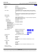
SAG582140001 Issue AN, June 4, 2014 System Application Guide Spec. No. 582140001 (Model 801NLDB, 801NLEB, 801NL-B) Home Family: Spec. No.: Model: Input Voltage Output Voltage: Output Capacity: System: NETSURE™ 582140001 801NLDB (208V Input Power Bay) 801NLEB (380V/480V Input Power Bay) 801NL-B (Distribution Bay) Nominal 380/480 volts AC, three phase, 50/60 Hz, with an operating range of 260 to 530 volts. Acceptable input frequency range is 45 to 65 Hz.
System Application Guide Spec. No. 582140001 (Model 801NLDB, 801NLEB, 801NL-B) Maximum Number of Distribution Bays per System: Control: Color: Environment: Configurations: SAG582140001 Issue AN, June 4, 2014 Home 8 Microprocessor Gray 0°C to +40°C (+32°F to +104°F) Plant is designed for centralized configuration with customer supplied Main Battery Termination Bars (MBTB’s). Emerson Network Power Services has standard MBTB’S in 4000, 6000, 10000, and 16000 ampere capacities.
SAG582140001 Issue AN, June 4, 2014 System Application Guide Spec. No. 582140001 (Model 801NLDB, 801NLEB, 801NL-B) Home 582140001 Power Bays List 0A: 380/480VAC Plant Input List 04: Primary Power Bay (2 AC Input Feeds) (Includes Circuit Breakers, One per Two Rectifier Modules) List 0B: 208VAC Plant Input List 05: Primary Power Bay (12 or 24 AC Input Feeds) AC Input Termination Panel and Optional AC Input Breakers List 06: Primary Power Bay (6 Input Feeds) 480V only.
System Application Guide Spec. No.
SAG582140001 Issue AN, June 4, 2014 System Application Guide Spec. No.
SAG582140001 Issue AN, June 4, 2014 System Application Guide Spec. No. 582140001 (Model 801NLDB, 801NLEB, 801NL-B) TABLE OF CONTENTS System Overview Picture List Descriptions Accessory Descriptions Specifications Physical Size Information Related Documentation SYSTEM OVERVIEW................................................................................................................................................. 1 582140001 Power Bays ..........................................................
SAG582140001 Issue AN, June 4, 2014 System Application Guide Spec. No. 582140001 (Model 801NLDB, 801NLEB, 801NL-B) AC Input (12 or 24 AC Input Feeds) Wire and Conduit Sizes, Branch Circuit Protection, and Lugs Selection Lists 5 and 13 ................................................................................................................................. 50 AC Input (6 AC Input Feeds) Wire and Conduit Sizes, Branch Circuit Protection, and Lugs Selection Lists 6 and 14 .............................
System Application Guide Spec. No. 582140001 (Model 801NLDB, 801NLEB, 801NL-B) SAG582140001 Issue AN, June 4, 2014 Home LIST DESCRIPTIONS List 0A: 380/480VAC Plant Input Voltage Features ♦ Specifies 380/480VAC Plant Input Voltage. List 0B: 208VAC Plant Input Voltage Features ♦ Specifies 208VAC Plant Input Voltage. List 04: Primary Power Bay (2 AC Input Feeds) Features ♦ Provides common equipment for one (1) Power Bay rated for up to 2400 amperes. ♦ Mounted in a 7'0"H x 24.
SAG582140001 Issue AN, June 4, 2014 System Application Guide Spec. No. 582140001 (Model 801NLDB, 801NLEB, 801NL-B) List 05: Primary Power Bay (12 or 24 AC Input Feeds) Features Home ♦ Provides common equipment for one (1) Power Bay rated for up to 2400 amperes. ♦ Mounted in a 7'0"H x 24.375"W x 30"D seismic rated (Zone 4) box framework. ♦ Provides twenty-four (24) Rectifier Module mounting positions.
System Application Guide Spec. No. 582140001 (Model 801NLDB, 801NLEB, 801NL-B) SAG582140001 Issue AN, June 4, 2014 Home ♦ Side cover panels are factory installed on both sides of the bay. Restrictions Only one (1) Primary Bay per power system required. 480V only. Ordering Notes 1) Specify List A (480VAC Input). 2) Order up to twenty-four (24) Rectifiers Modules per bay per List 22 (380/480VAC Input).
SAG582140001 Issue AN, June 4, 2014 System Application Guide Spec. No. 582140001 (Model 801NLDB, 801NLEB, 801NL-B) Home 7) Order “Power Bay Frame Grounding” lugs as required per Power Bay Frame Grounding Wire Sizes and Lugs Selection in the ACCESSORY DESCRIPTIONS section. 8) If a different length LMS and/or MCA Network cable is required, order per Replacement/Additional LMS Network Cables and/or Replacement/Additional MCA Network Cables.
System Application Guide Spec. No. 582140001 (Model 801NLDB, 801NLEB, 801NL-B) SAG582140001 Issue AN, June 4, 2014 List 14: Secondary Power Bay (6 AC Input Feeds) Features Home ♦ Provides common equipment for one (1) Power Bay rated for up to 2400 amperes. ♦ Mounted in a 7'0"H x 24.375"W x 30"D seismic rated (Zone 4) box framework. ♦ Provides twenty-four (24) Rectifier Module mounting positions.
SAG582140001 Issue AN, June 4, 2014 System Application Guide Spec. No. 582140001 (Model 801NLDB, 801NLEB, 801NL-B) Home Ordering Notes 1) Order distribution fuse and/or circuit breaker devices as required per Distribution Devices in the ACCESSORY DESCRIPTIONS section. 2) Order load distribution lugs as required per Load Distribution Wire Sizes and Lugs Selection (Distribution Bay) in the ACCESSORY DESCRIPTIONS section.
System Application Guide Spec. No. 582140001 (Model 801NLDB, 801NLEB, 801NL-B) SAG582140001 Issue AN, June 4, 2014 Home Restrictions The LMS Monitoring System Main CPU circuit card is mounted in the Primary Power Bay only. Ordering Notes 1) Order the optional LMS Monitor if increased monitoring capabilities are required. Order the LMS Main CPU circuit card (List 50) for the Primary Power Bay.
SAG582140001 Issue AN, June 4, 2014 System Application Guide Spec. No. 582140001 (Model 801NLDB, 801NLEB, 801NL-B) List 65: Interface Kit to a Spec. No. 582121901 Power System equipped with an LMS1000 Features ♦ Home Provides the following... LMS Dual MCA Interface Software Option P/N 506153 LMS Expansion CPU Card P/N 514641 150’ Echelon Cable P/N 526843 50’ LMS Dual MCA Option Cable LMS Dual MCA Interface Software Option enables the Spec. No.
System Application Guide Spec. No. 582140001 (Model 801NLDB, 801NLEB, 801NL-B) SAG582140001 Issue AN, June 4, 2014 Home List 70: Additional MCA Six (6) Output Form-C Relay Circuit Card Features ♦ Provides six relays each with one set of Form-C relay contacts. ♦ These relays are used for alarm applications and can be programmed by the user. ♦ Refer to the "Specifications" section of this document for further information.
SAG582140001 Issue AN, June 4, 2014 System Application Guide Spec. No. 582140001 (Model 801NLDB, 801NLEB, 801NL-B) List 0C: 24 Position Bullet-Nose Circuit Breaker/Fuse Panel Features ♦ Provides twenty-four (24) Bullet Nose Device positions. ♦ Accepts a choice of TLS/TPS-type fuseholders, Bullet Nose-Type circuit breakers, or Bullet NoseType GMT Fuse Modules. ♦ The List C Fuse/Circuit Breaker Panel is equipped with one (1) shunt for all distribution positions for MCA load current measurements.
System Application Guide Spec. No. 582140001 (Model 801NLDB, 801NLEB, 801NL-B) SAG582140001 Issue AN, June 4, 2014 Home ACCESSORY DESCRIPTIONS Seismic Anchor Kit, P/N 545387 Features Provides four (4) Relay Rack Seismic Mounting Anchors, P/N 216821200. Ordering Notes 1) Order Seismic Anchor Kit, P/N 545387, as required. Seismic Anchor Isolation Kit, P/N 545388 Features Provides four (4) bushings, P/N 124866 (one per seismic anchor) and one (1) insulator, P/N 112490.
SAG582140001 Issue AN, June 4, 2014 System Application Guide Spec. No. 582140001 (Model 801NLDB, 801NLEB, 801NL-B) Home Page 22 of 115 This document is property of Emerson Network Power, Energy Systems, North America, Inc. and contains confidential and proprietary information owned by Emerson Network Power, Energy Systems, North America, Inc. Any copying, use, or disclosure of it without the written permission of Emerson Network Power, Energy Systems, North America, Inc. is strictly prohibited.
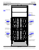
System Application Guide Spec. No. 582140001 (Model 801NLDB, 801NLEB, 801NL-B) SAG582140001 Issue AN, June 4, 2014 Home Rear View Rear View Rear cover panels removed in illustration for clarity.
SAG582140001 Issue AN, June 4, 2014 System Application Guide Spec. No. 582140001 (Model 801NLDB, 801NLEB, 801NL-B) Home 1-Position Devices (Load Busbars with NO Lug Adapters Installed) (see Note 6) 3-Position Lug Adapter Kit P/N 529131 (see Notes 2, 3, 4, 5) 4-Position Lug Adapter Kit P/N 534420 (see Notes 2, 3, 4) 2-Position Lug Adapter Kit P/N 529132 (see Notes 1, 3, 4, 5) Notes: 1. Lug adapter accepts a maximum of (2) 750 kcmil or (4) 350 kcmil lugs. 2.
System Application Guide Spec. No. 582140001 (Model 801NLDB, 801NLEB, 801NL-B) SAG582140001 Issue AN, June 4, 2014 Home Distribution Devices See Distribution Device and Load Lug Locations at the beginning of this section for illustrations of distribution device and load lug mounting locations. 218 Circuit Breaker Assemblies Features ♦ Each circuit breaker assembly is equipped with a shunt for MCA load current measurements. ♦ Bolts into bay's distribution device mounting positions.
SAG582140001 Issue AN, June 4, 2014 System Application Guide Spec. No. 582140001 (Model 801NLDB, 801NLEB, 801NL-B) Home Ampere Rating No.
SAG582140001 Issue AN, June 4, 2014 System Application Guide Spec. No. 582140001 (Model 801NLDB, 801NLEB, 801NL-B) Home Lug Adapter Kit NO LUG ADAPTER KIT REQUIRED 1-Pole 218 Circuit Breakers Assemblies Lug Adapter Kit 3/8" Clearance Hole 1.000" 2-Pole 218 Circuit Breaker Assemblies 2-Position Lug Adapter Kit P/N 529132 (see Notes 1, 2, 3, 4) Notes: 1. Lug adapter accepts a maximum of (2) 750 kcmil or (4) 350 kcmil lugs. 2. Lugs are not part of the kit, shown for illustration only. 3.
SAG582140001 Issue AN, June 4, 2014 System Application Guide Spec. No. 582140001 (Model 801NLDB, 801NLEB, 801NL-B) Home Lug Adapter Kit 1.000" 3-Pole 218 Circuit Breaker Assemblies 3/8" Clearance Hole 3-Position Lug Adapter Kit P/N 529131 (see Notes 1, 2, 3, 4) Lug Adapter Kit 1.000" 3/8" Clearance Hole 4-Position Lug Adapter Kit P/N 534420 (see Notes 1, 2, 3, 5) 4-Pole 218 Circuit Breaker Assemblies Notes: 1. Lug adapter accepts a maximum of (4) 750 kcmil lugs. 2.
SAG582140001 Issue AN, June 4, 2014 System Application Guide Spec. No. 582140001 (Model 801NLDB, 801NLEB, 801NL-B) Home TPL Fuses and Fuseholder Assemblies Features ♦ Each fuseholder assembly is equipped with a shunt for MCA load current measurements. ♦ Bolts into bay's distribution device mounting positions. Load lug busbars and adapter plates provide 3/8" clearance holes on 1" centers for installation of customer provided two-hole lugs. Restrictions Load should not exceed 80% of device rating.
SAG582140001 Issue AN, June 4, 2014 System Application Guide Spec. No. 582140001 (Model 801NLDB, 801NLEB, 801NL-B) Home Lug Adapter Kit 3/8" Clearance Hole 1.000" 2-Position Lug Adapter Kit P/N 529132 (see Notes 1, 2, 3, 4) TPL Fuse GMT-18/100A Alarm Fuse and GMT-X Safety Fuse Cover Fuseholder Assembly P/N 514403 Notes: 1. Lug adapter accepts a maximum of (2) 750 kcmil or (4) 350 kcmil lugs. 2. Lugs are not part of the kit, shown for illustration only. 3.
SAG582140001 Issue AN, June 4, 2014 System Application Guide Spec. No. 582140001 (Model 801NLDB, 801NLEB, 801NL-B) Home Lug Adapter Kit TPL Fuse GMT-18/100A Alarm Fuse and GMT-X Safety Fuse Cover Fuseholder Assembly P/N 514404 1.000" 3/8" Clearance Hole 3-Position Lug Adapter Kit P/N 529131 (see Notes 1, 2, 3, 4) Notes: 1. Lug adapter accepts a maximum of (4) 750 kcmil lugs. 2. Lugs are not part of the kit, shown for illustration only. 3.
SAG582140001 Issue AN, June 4, 2014 System Application Guide Spec. No. 582140001 (Model 801NLDB, 801NLEB, 801NL-B) Bullet Nose-Type Circuit Breakers and Bullet Nose-Type Fuseholders e/w TLS/TPS Fuses Features Home ♦ Installs in the optional List C Fuse/Circuit Breaker Panel. ♦ Load lugs are connected to busbars provided on the List C Fuse/Circuit Breaker Panel. These busbars provide 1/4-20 threaded holes on 5/8" centers for installation of customer provided two-hole lugs.
SAG582140001 Issue AN, June 4, 2014 System Application Guide Spec. No.
SAG582140001 Issue AN, June 4, 2014 System Application Guide Spec. No.
SAG582140001 Issue AN, June 4, 2014 System Application Guide Spec. No.
SAG582140001 Issue AN, June 4, 2014 System Application Guide Spec. No. 582140001 (Model 801NLDB, 801NLEB, 801NL-B) Home Note: Load Leads are connected to load busbars. These busbars provide 1/4-20 threaded holes on 5/8” centers for installation of customer provided two-hole lugs. Customer must provide lug mounting bolts and additional hardware. Bolt length: 3/4”.
SAG582140001 Issue AN, June 4, 2014 System Application Guide Spec. No. 582140001 (Model 801NLDB, 801NLEB, 801NL-B) Home Optional Bullet Nose-Type 10-Position GMT Fuse Module for List C Features ♦ Installs in the optional List C Fuse/Circuit Breaker Panel. ♦ Provides 10 GMT fuse positions. (1/4A to 15A GMT Alarm-Type Fuses). ♦ Screw clamp type load and load return terminals provided. ♦ Includes ten dummy fuses equipped with safety fuse covers. ♦ Includes 35A input fuse and associate alarm fuse.
SAG582140001 Issue AN, June 4, 2014 System Application Guide Spec. No. 582140001 (Model 801NLDB, 801NLEB, 801NL-B) Home Replacement Alarm, Reference, and Control Fuses Fuseblock Located in Bay’s Left Center Features Alarm, reference, and control fuses are located on the fuseblock mounted in the left center of the Power Bays and Distribution Bays. These fuses are not available for customer connected loads.
SAG582140001 Issue AN, June 4, 2014 System Application Guide Spec. No. 582140001 (Model 801NLDB, 801NLEB, 801NL-B) Input and Alarm Fuse on Optional Bullet Nose-Type 10-Position GMT Fuse Module, P/N 509128 Features Home Located on the optional Bullet Nose-Type 10-Position GMT Fuse Module (P/N 509128) is an input fuse. If this fuse opens, an alarm type fuse also opens to activate the fuse alarm circuit. The alarm-type fuse is located in fuse position #11 on the Fuse Module.
SAG582140001 Issue AN, June 4, 2014 System Application Guide Spec. No. 582140001 (Model 801NLDB, 801NLEB, 801NL-B) Home Wiring Components Load Distribution Wire Sizes and Lugs Selection (Distribution Bay) Features ♦ Load distribution leads are connected as described in the section titled Distribution Devices under "Accessory Descriptions". For lug mounting hole size and spacing dimensions, refer to the illustrations in the section titled Distribution Devices under "Accessory Descriptions".
SAG582140001 Issue AN, June 4, 2014 System Application Guide Spec. No.
SAG582140001 Issue AN, June 4, 2014 System Application Guide Spec. No.
SAG582140001 Issue AN, June 4, 2014 System Application Guide Spec. No.
SAG582140001 Issue AN, June 4, 2014 System Application Guide Spec. No. 582140001 (Model 801NLDB, 801NLEB, 801NL-B) Home Power Bay DC Output Cable Sizes and Lugs Selection Features ♦ 3/8” clearance holes on 1" centers are provided for installation of customer provided DC output cables terminated in two-hole lugs. These are accessed from the rear of each Power Bay. ♦ For lug mounting hole size and spacing dimensions, refer to the illustration provided in this section.
SAG582140001 Issue AN, June 4, 2014 System Application Guide Spec. No. 582140001 (Model 801NLDB, 801NLEB, 801NL-B) Home 3/8" Clearance Hole (21) 2.00" 1.00" 1.25" DC Output Negative Busbar (-) (Supply -48V Bus) DC Output Positive Busbar (+) (Ground Return Bus) Rear Cover Panel Removed in Illustration Rear View Power Bay Page 45 of 115 This document is property of Emerson Network Power, Energy Systems, North America, Inc.
SAG582140001 Issue AN, June 4, 2014 System Application Guide Spec. No. 582140001 (Model 801NLDB, 801NLEB, 801NL-B) Home Distribution Bay DC Input Cable Sizes and Lugs Selection Features ♦ 3/8” clearance holes on 1" centers are provided for installation of customer provided DC input cables terminated in two-hole lugs. These are accessed from the rear of each Distribution Bay. ♦ For lug mounting hole size and spacing dimensions, refer to the illustration provided in this section.
SAG582140001 Issue AN, June 4, 2014 System Application Guide Spec. No. 582140001 (Model 801NLDB, 801NLEB, 801NL-B) Home 3/8" Clearance Hole (22) DC Input (Supply -48V) 2.031" 1.00" 1.00" 1.00" 1.00" 1.00" 1.00" 1.00" 1.00" Rear View Distribution Bay Page 47 of 115 This document is property of Emerson Network Power, Energy Systems, North America, Inc. and contains confidential and proprietary information owned by Emerson Network Power, Energy Systems, North America, Inc.
SAG582140001 Issue AN, June 4, 2014 System Application Guide Spec. No. 582140001 (Model 801NLDB, 801NLEB, 801NL-B) Power Bay Frame Grounding Wire Sizes and Lugs Selection Features Home 1/4” clearance holes on 5/8" centers are provided for installation of customer provided two-hole lugs, as shown in the following illustration. Restrictions All lugs for customer connections must be ordered separately. Customer needs to supply lug mounting bolts and hardware.
System Application Guide Spec. No. 582140001 (Model 801NLDB, 801NLEB, 801NL-B) Distribution Bay Frame Grounding Wire Sizes and Lugs Selection Features SAG582140001 Issue AN, June 4, 2014 Home 1/4” clearance holes on 5/8" centers are provided for installation of customer provided two-hole lugs, as shown in the following illustration. Restrictions All lugs for customer connections must be ordered separately. Customer needs to supply lug mounting bolts and hardware.
SAG582140001 Issue AN, June 4, 2014 System Application Guide Spec. No. 582140001 (Model 801NLDB, 801NLEB, 801NL-B) AC Input (12 or 24 AC Input Feeds) Wire and Conduit Sizes, Branch Circuit Protection, and Lugs Selection Lists 5 and 13 Features Home ♦ 10-32 studs on 5/8” centers are provided for installation of customer provided two-hole AC Input lugs. ♦ 1/4-20 studs are provided for installation of customer provided two-hole AC equipment grounding lugs.
SAG582140001 Issue AN, June 4, 2014 System Application Guide Spec. No. 582140001 (Model 801NLDB, 801NLEB, 801NL-B) Home 24 Feeds Input Voltage Input Current Overcurrent Protection (1) 40°C Ambient Temperature (2) Wire AWG (2) (3) Conduit Size (in.) THWN - 75°C Wire - Individual Feed Three Rectifiers (9 Current and 1 Ground Wire) per Conduit 480V 380V 208V 7.
SAG582140001 Issue AN, June 4, 2014 System Application Guide Spec. No. 582140001 (Model 801NLDB, 801NLEB, 801NL-B) Home 12 Feeds Input Voltage Input Current Overcurrent Protection (1) 40°C Ambient Temperature (2) Wire AWG (2) (3) Conduit Size (in.) THWN - 75°C Wire - Individual Feed Four Rectifiers (6 Current and 1 Ground Wire) per Conduit 480V 380V 208V 15.6A 20A 35.
System Application Guide Spec. No. 582140001 (Model 801NLDB, 801NLEB, 801NL-B) AC Input (6 AC Input Feeds) Wire and Conduit Sizes, Branch Circuit Protection, and Lugs Selection Lists 6 and 14 Features SAG582140001 Issue AN, June 4, 2014 Home ♦ 10-32 studs on 5/8” centers are provided for installation of customer provided two-hole AC Input lugs. ♦ 1/4-20 studs are provided for installation of customer provided two-hole AC equipment grounding lugs.
SAG582140001 Issue AN, June 4, 2014 System Application Guide Spec. No. 582140001 (Model 801NLDB, 801NLEB, 801NL-B) Home 6 Feeds Input Voltage Input Current Overcurrent Protection (1) 40°C Ambient Temperature (2) Wire AWG (2) (3) Conduit Size (in.
System Application Guide Spec. No. 582140001 (Model 801NLDB, 801NLEB, 801NL-B) SAG582140001 Issue AN, June 4, 2014 Home See Detail A (12 Feeds) Six (6) 1.125" openings for 3/4" conduit. Two (2) conduit plates with 2.5", 1.75", and 1.125" knock-outs for 2", 1.5", and 3/4" conduit. Six (6) 1.75" openings for 1.5" conduit (under plate). See Detail B (24 Feeds) See Detail C (6 Feeds) Top View Power Bay Front cover panel omitted Note: Rectifier numbering is for wiring identification only.
SAG582140001 Issue AN, June 4, 2014 System Application Guide Spec. No.
System Application Guide Spec. No.
SAG582140001 Issue AN, June 4, 2014 System Application Guide Spec. No.
System Application Guide Spec. No. 582140001 (Model 801NLDB, 801NLEB, 801NL-B) AC Input (2 AC Input Feeds) Wire and Conduit Sizes, Branch Circuit Protection, and Lugs Selection Lists 4 and 12 Features SAG582140001 Issue AN, June 4, 2014 Home ♦ 3/8-16 studs on 1” centers are provided for installation of customer provided two-hole AC Input lugs. ♦ 1/4-20 studs are provided for installation of customer provided two-hole AC equipment grounding lugs.
SAG582140001 Issue AN, June 4, 2014 System Application Guide Spec. No. 582140001 (Model 801NLDB, 801NLEB, 801NL-B) Home Input Voltage Input Current Overcurrent Protection (1) 40°C Ambient Temperature (2) Wire AWG (2) (3) Conduit Size (in.
SAG582140001 Issue AN, June 4, 2014 System Application Guide Spec. No. 582140001 (Model 801NLDB, 801NLEB, 801NL-B) Home 380/480VAC (List A) or 208VAC (List B) 3 Phase, 50/60Hz (2 AC Input Feeds, 1 per 12 Rectifier Modules) Odd Numbered Rectifier Mounting Slots C B A Equipment Grounding (1/4-20 Studs on 1" Centers) Even Numbered Rectifier Mounting Slots A B C AC Input (3/8-16 Studs on 1" Centers) Front cover panel removed in illustration Six (6) 1.125" openings for 3/4" conduit.
SAG582140001 Issue AN, June 4, 2014 System Application Guide Spec. No. 582140001 (Model 801NLDB, 801NLEB, 801NL-B) Home External Alarm, Reference, and Control Wire Sizes - Power Bays Features ♦ External Alarm, Reference, and Control connections are made to TB1 on the MCA circuit card and TB1 on the MCA Customer Alarm Relay Circuit Cards. Terminals Recm Wire Size Capacity Type 28 to 16 AWG Screw Clamp 22 AWG for Loop Lengths Up to 200 ft. 18-20 AWG for Loop Lengths Over 200 ft.
SAG582140001 Issue AN, June 4, 2014 System Application Guide Spec. No. 582140001 (Model 801NLDB, 801NLEB, 801NL-B) Home Optional Battery Charge Temperature Compensation Probe for Digital Compensation Features ♦ This system can be used with a Battery Charge Temperature Compensation Probe. This probe must be mounted near the battery to sense battery ambient temperature.
SAG582140001 Issue AN, June 4, 2014 System Application Guide Spec. No. 582140001 (Model 801NLDB, 801NLEB, 801NL-B) Replacement/Additional MCA Network Cable Home Features ♦ MCA bay-to-bay interconnect cable. Connects between bay expansion ports located on the bay's MCA (Primary Power Bay) and Router (Secondary Power Bays and Distribution Bays) circuit cards. ♦ Cable identification color is yellow. Restrictions Maximum combined cable length must not exceed 125 feet.
SAG582140001 Issue AN, June 4, 2014 System Application Guide Spec. No. 582140001 (Model 801NLDB, 801NLEB, 801NL-B) Home Replacement Modules and Circuit Cards Ordering Notes 1) Refer to the following table.
SAG582140001 Issue AN, June 4, 2014 System Application Guide Spec. No. 582140001 (Model 801NLDB, 801NLEB, 801NL-B) Home SPECIFICATIONS 1. SYSTEM 1.1 DC Operating Voltage 1.1.1 Nominal: -48Vdc. 1.1.2 Range: -42Vdc to -60Vdc. 1.2 Environmental Ratings Note: See also ‘Environmental Ratings’ in the Rectifier Module section. 1.2.1 Operating Ambient Temperature Range: 0°C to +40°C (+32°F to +104°F). 1.2.2 Storage Ambient Temperature Range: -40°C to +65°C (-40°F to +149°F). 1.2.
System Application Guide Spec. No. 582140001 (Model 801NLDB, 801NLEB, 801NL-B) 1.3 1.4 SAG582140001 Issue AN, June 4, 2014 Home 1.2.11 Electrical Fast Transient / Burst Immunity: Complies with EN61000-4-4 Level 4. 1.2.12 Mounting: This Power System is intended only for installation in a Restricted Access Location on or above a non-combustible surface. Typical industry standards recommend minimum aisle space clearance of 2'6" for the front of the relay rack and 2' for the rear of the relay rack.
SAG582140001 Issue AN, June 4, 2014 System Application Guide Spec. No. 582140001 (Model 801NLDB, 801NLEB, 801NL-B) Home Note that some fuse/circuit breaker combinations require more than one fuse/circuit breaker mounting position. Refer to Distribution Devices under ACCESSORY DESCRIPTIONS for details. The optional Distribution Panel provides twenty-four (24) Bullet Nose Device positions. The panel accepts a choice of TLS/TPS-type fuseholders or Bullet Nose-type circuit breakers.
SAG582140001 Issue AN, June 4, 2014 System Application Guide Spec. No. 582140001 (Model 801NLDB, 801NLEB, 801NL-B) Home Output Voltage vs. Output Current, Max. Output Power 5800 W Output Voltage (V) 70 60 50 40 30 20 10 0 0 10 20 30 40 50 60 70 80 90 100 110 120 130 140 150 160 Output Current (A) 3.1.5 Power Derating Based on Input Voltage: The Rectifier Module power varies with changes in input voltage and output voltage. It uses an advanced power limitation method.
SAG582140001 Issue AN, June 4, 2014 System Application Guide Spec. No. 582140001 (Model 801NLDB, 801NLEB, 801NL-B) Home Output power vs. Temperature at Uin > 304 VAC % of output power 120 100 80 60 40 20 0 -40 -30 -20 -10 0 10 20 30 40 50 60 70 80 Temperature (C) 3.1.7 Regulation (Rectifier Module) (A) Voltage Regulation: ≤±1% (B) Load Regulation: ≤±0.5% (C) Line Regulation: ≤±0.
SAG582140001 Issue AN, June 4, 2014 System Application Guide Spec. No. 582140001 (Model 801NLDB, 801NLEB, 801NL-B) 3.2 AC Input Ratings 3.2.1 Voltage: Nominal 380/480 volts AC, three phase, 50/60 Hz, with an operating range of 260 to 530 volts. Acceptable input frequency range is 45 to 65 Hz. Maximum non-destructive input voltage when rectifier is not operating: 600 VAC 3.2.2 Current: <13A @ 5800 W, and at an input voltage of 260 VAC. 3.2.
SAG582140001 Issue AN, June 4, 2014 • System Application Guide Spec. No. 582140001 (Model 801NLDB, 801NLEB, 801NL-B) Between the AC input and the DC output: ≥20x106 Ω Home • Between the DC output and the enclosure: ≥20x106 Ω (B) Dielectric Strength 3.3.7 3.3.8 • Between the AC input and the enclosure: the leakage current is <1 mA, with no breakdown within 1 minute using an applied voltage of 2120 V.
SAG582140001 Issue AN, June 4, 2014 System Application Guide Spec. No. 582140001 (Model 801NLDB, 801NLEB, 801NL-B) Home Item Standard EN61000-4-5 Surge Immunity EFT Class AC Port: 4kV/2Ω 6kV/12Ω for com. DC Port: 800V/2Ω CAN Bus: 1kV diff. / 2kV com. GR-1089-CORE R4-8, R4-9, R4-24, R-25 EN 61000-4-4 AC and DC Port: 4kV CAN Bus: 1kV GR-1089-CORE O2-8 EN 61000-4-2 and Conducted immunity GR-1089-CORE Radiated immunity EN 61000-4-6 GR-1089-CORE 8kV/15kV R2-1, R2-2, R2-3, O2-4 3Vrms 0.
SAG582140001 Issue AN, June 4, 2014 System Application Guide Spec. No. 582140001 (Model 801NLDB, 801NLEB, 801NL-B) Home 3.4 Standard Features 3.4.1 Type of Power Conversion Circuit: High frequency. 3.4.2 Float Charging Output Mode: In this mode of operation, system output voltage is constant and output current does not exceed the current limit setting. During normal operation, the battery is not required to furnish load current and remains in a fully charged condition.
System Application Guide Spec. No. 582140001 (Model 801NLDB, 801NLEB, 801NL-B) 3.4.5 3.4.6 SAG582140001 Issue AN, June 4, 2014 Home (D) Method 4 (External Test/Equalize): A user (or external equipment) places the system into the test/equalize mode by applying an external signal to the system. The system returns to the float mode when the external signal is removed. This method overrides the other three methods.
SAG582140001 Issue AN, June 4, 2014 System Application Guide Spec. No. 582140001 (Model 801NLDB, 801NLEB, 801NL-B) Home High Temperature Protection: (A) When the PFC board temperature is higher than 85°C, the rectifier turns off. When the PFC board temperature is lower than 75°C, the rectifier resumes to normal operation, and the hysteresis is at least 10°C. (B) When the “ambient temperature – PFC board temperature” is higher than 5°C, the rectifier turns off.
SAG582140001 Issue AN, June 4, 2014 System Application Guide Spec. No. 582140001 (Model 801NLDB, 801NLEB, 801NL-B) Home 3.4.18 Monitoring Function: The Rectifier Module has a built-in advanced DSP that monitors and controls the operation of the Rectifier Module. The DSP also communicates with the Controller in real time through the CAN bus. The following table lists the different commands and information exchanged between the Rectifier Module and the Controller.
SAG582140001 Issue AN, June 4, 2014 System Application Guide Spec. No. 582140001 (Model 801NLDB, 801NLEB, 801NL-B) 4. RECTIFIER MODULE (MODEL R48-5800L, SPEC. NO. 1R485800L) 4.1 DC Output Ratings 4.1.1 Voltage: Nominal -48 volts DC, Positive Ground. (A) Without Battery Charge Temperature Compensation: Float voltage is adjustable from 47.00 to 58.00 volts DC. Test/equalize voltage is adjustable from 45.00 to 58.00 volts DC. Adjustment is made via the MCA.
SAG582140001 Issue AN, June 4, 2014 System Application Guide Spec. No. 582140001 (Model 801NLDB, 801NLEB, 801NL-B) Home Output voltage (V) Output voltage vs. output current, max. output power 5800 W 70 60 50 40 30 20 10 0 0 10 20 30 40 50 60 70 80 90 100 110 120 130 140 150 160 Output current (A) 4.1.5 Power Derating Based on Input Voltage: The Rectifier Module power varies with changes in input voltage and output voltage. It uses an advanced power limitation method.
SAG582140001 Issue AN, June 4, 2014 System Application Guide Spec. No. 582140001 (Model 801NLDB, 801NLEB, 801NL-B) Home Output power vs. Temperature at Uin > 166 VAC % of output power 120 100 80 60 40 20 0 -40 -30 -20 -10 0 10 20 30 40 50 60 70 80 Temperature (C) 4.1.7 Regulation (Rectifier Module) (A) Voltage Regulation: ≤±1% (B) Load Regulation: ≤±0.5% (C) Line Regulation: ≤±0.
SAG582140001 Issue AN, June 4, 2014 System Application Guide Spec. No. 582140001 (Model 801NLDB, 801NLEB, 801NL-B) 4.2 AC Input Ratings 4.2.1 Voltage: Nominal 208 volts AC, three phase, 50/60 Hz, with an operating range of 176 to 264 volts. Acceptable input frequency range is 45 to 65 Hz. Maximum non-destructive input voltage when rectifier is not operating: 600 VAC 4.2.2 Current: <18A @ 5800 W, and at an input voltage of 176 VAC. 4.2.
SAG582140001 Issue AN, June 4, 2014 4.3.6 System Application Guide Spec. No. 582140001 (Model 801NLDB, 801NLEB, 801NL-B) Insulation Resistance and Dielectric Strength (A) Insulation Resistance • Between the AC input and the enclosure: ≥20x106 Ω • Between the AC input and the DC output: ≥20x106 Ω Home • Between the DC output and the enclosure: ≥20x106 Ω (B) Dielectric Strength 4.3.7 4.3.
SAG582140001 Issue AN, June 4, 2014 System Application Guide Spec. No. 582140001 (Model 801NLDB, 801NLEB, 801NL-B) Home Item Standard EN61000-4-5 Surge Immunity EFT Class AC Port: 4kV/2Ω 6kV/12Ω for com. DC Port: 800V/2Ω CAN Bus: 1kV diff. / 2kV com. GR-1089-CORE R4-8, R4-9, R4-24, R-25 EN 61000-4-4 AC and DC Port: 4kV CAN Bus: 1kV GR-1089-CORE O2-8 EN 61000-4-2 and Conducted immunity GR-1089-CORE Radiated immunity EN 61000-4-6 GR-1089-CORE 8kV/15kV R2-1, R2-2, R2-3, O2-4 3Vrms 0.
SAG582140001 Issue AN, June 4, 2014 System Application Guide Spec. No. 582140001 (Model 801NLDB, 801NLEB, 801NL-B) Home 4.4 Standard Features 4.4.1 Type of Power Conversion Circuit: High frequency. 4.4.2 Float Charging Output Mode: In this mode of operation, system output voltage is constant and output current does not exceed the current limit setting. During normal operation, the battery is not required to furnish load current and remains in a fully charged condition.
System Application Guide Spec. No. 582140001 (Model 801NLDB, 801NLEB, 801NL-B) 4.4.5 4.4.6 SAG582140001 Issue AN, June 4, 2014 Home (D) Method 4 (External Test/Equalize): A user (or external equipment) places the system into the test/equalize mode by applying an external signal to the system. The system returns to the float mode when the external signal is removed. This method overrides the other three methods.
SAG582140001 Issue AN, June 4, 2014 System Application Guide Spec. No. 582140001 (Model 801NLDB, 801NLEB, 801NL-B) Home High Temperature Protection: (A) When the PFC board temperature is higher than 85°C, the rectifier turns off. When the PFC board temperature is lower than 75°C, the rectifier resumes to normal operation, and the hysteresis is at least 10°C. (B) When the “ambient temperature – PFC board temperature” is higher than 5°C, the rectifier turns off.
SAG582140001 Issue AN, June 4, 2014 System Application Guide Spec. No. 582140001 (Model 801NLDB, 801NLEB, 801NL-B) 4.4.18 Monitoring Function: The Rectifier Module has a built-in advanced DSP that monitors and controls the operation of the Rectifier Module. The DSP also communicates with the Controller in real time through the CAN bus. The following table lists the different commands and information exchanged between the Rectifier Module and the Controller.
SAG582140001 Issue AN, June 4, 2014 System Application Guide Spec. No. 582140001 (Model 801NLDB, 801NLEB, 801NL-B) 5. RECTIFIER MODULE (MODEL R48-5800E SPEC. NO. 1R485800E) 5.1 DC Output Ratings 5.1.1 Voltage: Nominal -48 volts DC, Positive Ground. (A) Without Battery Charge Temperature Compensation: Float voltage is adjustable from 47.00 to 58.00 volts DC. Test/equalize voltage is adjustable from 45.00 to 58.00 volts DC. Adjustment is made via the MCA.
SAG582140001 Issue AN, June 4, 2014 System Application Guide Spec. No. 582140001 (Model 801NLDB, 801NLEB, 801NL-B) Home Output Voltage vs. Output Current, Max. Output Power 5800 W Output Voltage (V) 70 60 50 40 30 20 10 0 0 10 20 30 40 50 60 70 80 90 100 110 120 130 140 150 160 Output Current (A) 5.1.5 Power Derating Based on Input Voltage: The Rectifier Module power varies with changes in input voltage and output voltage. It uses an advanced power limitation method.
SAG582140001 Issue AN, June 4, 2014 System Application Guide Spec. No. 582140001 (Model 801NLDB, 801NLEB, 801NL-B) Home Output power vs. Temperature at Uin > 304 VAC % of output power 120 100 80 60 40 20 0 -40 -30 -20 -10 0 10 20 30 40 50 60 70 80 Temperature (C) 5.1.7 Regulation (Rectifier Module) (A) Voltage Regulation: ≤±1% (B) Load Regulation: ≤±0.5% (C) Line Regulation: ≤±0.
SAG582140001 Issue AN, June 4, 2014 System Application Guide Spec. No. 582140001 (Model 801NLDB, 801NLEB, 801NL-B) 5.2 AC Input Ratings 5.2.1 Voltage: Nominal 380/480 volts AC, three phase, 50/60 Hz, with an operating range of 260 to 530 volts. Acceptable input frequency range is 45 to 65 Hz. Maximum non-destructive input voltage when rectifier is not operating: 600 VAC 5.2.2 Current: <13A @ 5800 W, and at an input voltage of 260 VAC. 5.2.
SAG582140001 Issue AN, June 4, 2014 5.3.6 System Application Guide Spec. No. 582140001 (Model 801NLDB, 801NLEB, 801NL-B) Insulation Resistance and Dielectric Strength (A) Insulation Resistance • Between the AC input and the enclosure: ≥20x106 Ω • Between the AC input and the DC output: ≥20x106 Ω Home • Between the DC output and the enclosure: ≥20x106 Ω (B) Dielectric Strength 5.3.7 5.3.
SAG582140001 Issue AN, June 4, 2014 System Application Guide Spec. No. 582140001 (Model 801NLDB, 801NLEB, 801NL-B) Home Item Standard EN61000-4-5 Surge Immunity EFT Class AC Port: 4kV/2Ω 6kV/12Ω for com. DC Port: 800V/2Ω CAN Bus: 1kV diff. / 2kV com. GR-1089-CORE R4-8, R4-9, R4-24, R-25 EN 61000-4-4 AC and DC Port: 4kV CAN Bus: 1kV GR-1089-CORE O2-8 EN 61000-4-2 and Conducted immunity GR-1089-CORE Radiated immunity EN 61000-4-6 GR-1089-CORE 8kV/15kV R2-1, R2-2, R2-3, O2-4 3Vrms 0.
SAG582140001 Issue AN, June 4, 2014 System Application Guide Spec. No. 582140001 (Model 801NLDB, 801NLEB, 801NL-B) Home 5.4 Standard Features 5.4.1 Type of Power Conversion Circuit: High frequency. 5.4.2 Float Charging Output Mode: In this mode of operation, system output voltage is constant and output current does not exceed the current limit setting. During normal operation, the battery is not required to furnish load current and remains in a fully charged condition.
System Application Guide Spec. No. 582140001 (Model 801NLDB, 801NLEB, 801NL-B) 5.4.5 5.4.6 SAG582140001 Issue AN, June 4, 2014 Home (D) Method 4 (External Test/Equalize): A user (or external equipment) places the system into the test/equalize mode by applying an external signal to the system. The system returns to the float mode when the external signal is removed. This method overrides the other three methods.
SAG582140001 Issue AN, June 4, 2014 System Application Guide Spec. No. 582140001 (Model 801NLDB, 801NLEB, 801NL-B) Home High Temperature Protection: (A) When the PFC board temperature is higher than 85°C, the rectifier turns off. When the PFC board temperature is lower than 75°C, the rectifier resumes to normal operation, and the hysteresis is at least 10°C. (B) When the “ambient temperature – PFC board temperature” is higher than 5°C, the rectifier turns off.
SAG582140001 Issue AN, June 4, 2014 System Application Guide Spec. No. 582140001 (Model 801NLDB, 801NLEB, 801NL-B) Home 5.4.18 Monitoring Function: The Rectifier Module has a built-in advanced DSP that monitors and controls the operation of the Rectifier Module. The DSP also communicates with the Controller in real time through the CAN bus. The following table lists the different commands and information exchanged between the Rectifier Module and the Controller.
SAG582140001 Issue AN, June 4, 2014 System Application Guide Spec. No. 582140001 (Model 801NLDB, 801NLEB, 801NL-B) Home 6. MCA 6.1 Standard Features 6.1.1 MCA Interface: You interface with the MCA locally via the MCA Control Panel located on the outside of the primary Power Bay's front door. You can also interface with the MCA via the LMS, if furnished. Note: Option switches are provided to lockout changing adjustment/configuration/calibration settings via the MCA control panel and/or via the LMS. 6.1.
System Application Guide Spec. No. 582140001 (Model 801NLDB, 801NLEB, 801NL-B) SAG582140001 Issue AN, June 4, 2014 Home (N) Low Battery Ambient Temperature #2 Alarm (if battery charge digital temperature compensation probe installed): Adjustable from -49°C to +100°C. You disable the feature by selecting the setting below -49°C. Factory set to off, unless otherwise specified. (O) Audible Alarm Cutoff Reset Feature: Adjustable from 0 to 15 minutes, in one minute intervals.
SAG582140001 Issue AN, June 4, 2014 System Application Guide Spec. No. 582140001 (Model 801NLDB, 801NLEB, 801NL-B) 6.1.11 Local Controls: Refer to the "Operating Procedures" chapter in the Power System User Instructions (Section 6017) for a complete description.
SAG582140001 Issue AN, June 4, 2014 System Application Guide Spec. No. 582140001 (Model 801NLDB, 801NLEB, 801NL-B) 6.1.13 MCA Numbering Scheme: The MCA identifies (numbers) the components of the system as follows.
SAG582140001 Issue AN, June 4, 2014 System Application Guide Spec. No.
System Application Guide Spec. No. 582140001 (Model 801NLDB, 801NLEB, 801NL-B) SAG582140001 Issue AN, June 4, 2014 Home 6.1.14 MCA Display: Presented next are illustrations from the MCA Menu Tree (Section 5886). Refer to the latest version of Section 5886 for the most recent MCA Menu Tree. Refer to the Power System User Instructions (Section 6017) for a complete description of menu items (the MCA is used in multiple platforms, some menu items may not be available as detailed in Section 6017).
SAG582140001 Issue AN, June 4, 2014 System Application Guide Spec. No. 582140001 (Model 801NLDB, 801NLEB, 801NL-B) The User navigates Lines 3 and 4 of the MCA Display using the Keypad on the MCA Control Panel. (The following indicates the actual text shown on each line of Lines 3 and 4 of the MCA Display, Line 4 also displays applicable navigation key codes, see previous page for explanation of codes.
SAG582140001 Issue AN, June 4, 2014 System Application Guide Spec. No. 582140001 (Model 801NLDB, 801NLEB, 801NL-B) from (Sheet 1 of 4) A FUNCTION MENU (cont'd on next page) 105 133 134 VIEW THE SYSTEM MEASUREMENTS FLOAT MODE IS ACTIVE SET TEST/EQ? or TEST/EQ MODE ACTIVE SET FLOAT? or TEST/EQUALIZE INPUT IS ACTIVE or TURN OFF POWER SHARE or TURN OFF ALTERNATE CURRENT LIMIT MEASUREMENT MENU 106 SYSTEM OUTPUT SENSE vv.vvV (REM) or SYSTEM OUTPUT SENSE vv.
SAG582140001 Issue AN, June 4, 2014 System Application Guide Spec. No.
SAG582140001 Issue AN, June 4, 2014 System Application Guide Spec. No.
SAG582140001 Issue AN, June 4, 2014 System Application Guide Spec. No. 582140001 (Model 801NLDB, 801NLEB, 801NL-B) Home 6.1.15 External Control Circuits (A) Remote Test/Equalize: All Rectifier Modules can be placed into the test/equalize mode by applying a loop closure signal. The Rectifier Modules operate in the float mode when the loop closure signal is absent. (B) Remote High Voltage Shutdown: The high voltage shutdown circuit on all Rectifier Modules, as described in Paragraph 3.4.
System Application Guide Spec. No. 582140001 (Model 801NLDB, 801NLEB, 801NL-B) SAG582140001 Issue AN, June 4, 2014 Home System Current. The NPS controller will include the value of LMS function channel sixty-four when summing the distribution load currents to determine its Total Load Current reading to display. (associated LMS channel A9903). Channel F63 program line is ‘F63 = A9002’ (Vortex Total Load Current).
SAG582140001 Issue AN, June 4, 2014 System Application Guide Spec. No. 582140001 (Model 801NLDB, 801NLEB, 801NL-B) Home PHYSICAL SIZE INFORMATION Floor Hole Drilling Pattern Dimensions - Power Bays 0.812 Dia. (10 PLACES) 24.38 19.86 17.23 26.56 21.24 23.94 30.00 19.38 3.03 1.30 2.27 3.58 1.72 Front 3/8-16 Welded Nut (4) Floor Hole Drilling Pattern Dimensions - Distribution Bays 3/8-16 Welded Nut (4) 31.375 27.625 25.875 23.250 19.500 26.625 19.500 24.000 30.000 25.375 3.063 1.750 1.
SAG582140001 Issue AN, June 4, 2014 System Application Guide Spec. No. 582140001 (Model 801NLDB, 801NLEB, 801NL-B) Home Overall Dimensions - Primary and Secondary Power Bays Six (6) 1.125” openings for 3/4” conduit. Two (2) conduit plates with 2.5”, 1.75” and 1.125” knock-outs for 2”, 1.5” and 3/4” conduit. Six (6) 1.75” openings for 1.5” conduit (under plate). 30.00 AC Input Wiring Access Opening(s) Notes: 1. All dimensions are in inches unless otherwise specified. 2.
SAG582140001 Issue AN, June 4, 2014 System Application Guide Spec. No. 582140001 (Model 801NLDB, 801NLEB, 801NL-B) Home Overall Dimensions - Distribution Bays 30.00 Notes: 1. All dimensions are in inches unless otherwise specified. 2. Weight in Lbs: 916 Net: Shipping: 972 3. Finish: Gray Top View 31.375 84.00 Left Side View Front View Right Side View Page 112 of 115 This document is property of Emerson Network Power, Energy Systems, North America, Inc.
System Application Guide Spec. No. 582140001 (Model 801NLDB, 801NLEB, 801NL-B) SAG582140001 Issue AN, June 4, 2014 Home Overall Dimensions – Optional Battery Charge Digital Temperature Compensation Probes P/N 107021 (25 feet) and P/N 106824 (100 feet) 0.25 (6.35) DIA. 0.75 (19.05) 3.00 (76.2) 0.75 (19.05) 2.25 (57.15) 300 (7,620) or 1200 (30,480) 0.35 (8.89) NOTE: All dimensions are in inches and (millimeters).
SAG582140001 Issue AN, June 4, 2014 System Application Guide Spec. No.
SAG582140001 Issue AN, June 4, 2014 System Application Guide Spec. No. 582140001 (Model 801NLDB, 801NLEB, 801NL-B) Home REVISION RECORD Issue Change Number (ECO) AJ LLP216414 AK LLP216848 AL LLP216994 AM LLP219853 AN LLP220105 Description of Change Add 1R485800e rectifier as another option in NetSure 801 system, 582140001. Illustration in 5.1.4 updated. Removed 50Hz typical input data per Marketing. Misc. updates.