
Application Guide

SAG582140001 System Application Guide
Issue AN, June 4, 2014 Spec. No. 582140001 (Model 801
NLDB, 801NLEB, 801NL-B)
Page 14 of 115
This document is property of Emerson Network Power, Energy Systems, North America, Inc. and contains confidential and proprietary information owned by Emerson Network Power, Energy
Systems, North America, Inc. Any copying, use, or disclosure of it without the written permission of Emerson Network Power, Energy Systems, North America, Inc. is strictly prohibited.
7) Order “Power Bay Frame Grounding” lugs as required per Power Bay Frame Grounding Wire
Sizes and Lugs Selection in the ACCESSORY DESCRIPTIONS section.
8) If a different length LMS and/or MCA Network cable is required, order per Replacement/Additional LMS
Network Cables and/or Replacement/Additional MCA Network Cables. Refer to the Installation
Instructions (Section 6016) for Network cabling requirements.
9) Side cover panels are not provided. When bays are placed next to each other, the side cover panels
from the ‘inside’ side of the Primary Power Bay are moved to the ‘outside’ side of the last Secondary
Power Bay. In installations where a Secondary Power Bay is placed by itself, order (4) P/N 535092 side
cover panels.
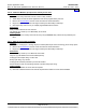
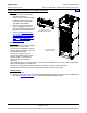
List 13: Secondary Power Bay (12 or 24 AC Input Feeds)
Features
♦ Provides common equipment for one (1) Power Bay rated for up to 2400 amperes.
♦ Mounted in a 7'0"H x 24.375"W x 30"D seismic rated (Zone 4) box framework.
♦ Provides twenty-four (24) Rectifier Module mounting positions.
♦ Provides an AC input termination panel that accepts twenty-four (24) AC input branch circuits [one (1) per
Rectifier Module mounting position] or twelve (12) AC input branch circuits [one (1) per two Rectifier
Module mounting positions]. The bay ships with the 12 Feed option installed.
♦ Includes a Router Assembly for bay communication to the MCA in the Primary Power Bay.
♦ Provides mounting for optional LMS Expansion CPU circuit card.
♦ Provides a seven-slot card cage for mounting MCA customer alarm relay circuit cards, MCA I/O circuit
cards, and/or optional LMS I/O circuit cards.
♦ MCA Network bay interconnect cable provided (Qty. 1 P/N 514642).
Ordering Notes
1) Specify List A (380/480VAC Input) or List B (208VAC Input).
2) Order up to twenty-four (24) Rectifiers Modules per bay per List 21 (208VAC Input) or List 22
(380/480VAC Input).
3) Order additional MCA customer alarm relay circuit card(s) as required per List 70, and optional MCA I/O
circuit cards per List 71.
4) Order optional LMS Expansion CPU circuit card and LMS options as required per List 63, and
SAG586505000. Also order additional LMS Network cables as required per Replacement/Additional LMS
Network Cables.
5) Order “Power Bay DC Output” lugs as required per Power Bay DC Output Cable Sizes and Lugs
Selection in the ACCESSORY DESCRIPTIONS section.
6) Order “AC Input Ground” lugs as required per AC Input (Individual/Twin AC Input Feeds) Wire and
Conduit Sizes, Branch Circuit Protection, and Lugs Selection in the ACCESSORY DESCRIPTIONS
section.
7) Order “Power Bay Frame Grounding” lugs as required per Power Bay Frame Grounding Wire Sizes and
Lugs Selection in the ACCESSORY DESCRIPTIONS section.
8) If a different length LMS and/or MCA Network cable is required, order per Replacement/Additional LMS
Network Cables and/or Replacement/Additional MCA Network Cables. Refer to the Installation
Instructions (Section 6016) for Network cabling requirements.
9) Side cover panels are not provided. When bays are placed next to each other, the side cover panels
from the ‘inside’ side of the Primary Power Bay are moved to the ‘outside’ side of the last Secondary
Power Bay. In installations where a Secondary Power Bay is placed by itself, order (4) P/N 535092 side
cover panels.
Home Home