
Application Guide


System Application Guide SAG582140001
Spec. No. 582140001 (Model 801
NLDB, 801NLEB, 801NL-B) Issue AN, June 4, 2014
Page 9 of 115
This document is property of Emerson Network Power, Energy Systems, North America, Inc. and contains confidential and proprietary information owned by Emerson Network Power, Energy
Systems, North America, Inc. Any copying, use, or disclosure of it without the written permission of Emerson Network Power, Energy Systems, North America, Inc. is strictly prohibited.
TABLE OF CONTENTS
System
Overview
Picture
List
Descriptions
Accessory
Descriptions
Specifications
Physical Size
Information
Related
Documentation
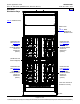
SYSTEM OVERVIEW ................................................................................................................................................. 1
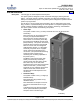
582140001 Power Bays ....................................................................................................................................... 6
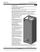
582140001 Distribution Bays .............................................................................................................................. 7
582140001 Power Bays Monitor and Control Diagram .................................................................................... 8
582140001 Distribution Bays Monitor and Control Diagram .......................................................................... 8
TABLE OF CONTENTS ............................................................................................................................................. 9
LIST DESCRIPTIONS .............................................................................................................................................. 11
List 0A: 380/480VAC Plant Input Voltage ..................................................................................................... 11
List 0B: 208VAC Plant Input Voltage ............................................................................................................ 11
List 04: Primary Power Bay (2 AC Input Feeds) ........................................................................................... 11
List 05: Primary Power Bay (12 or 24 AC Input Feeds) ................................................................................ 12
List 06: Primary Power Bay (6 AC Input Feeds) ........................................................................................... 12
List 12: Secondary Power Bay (2 AC Input Feeds) ...................................................................................... 13
List 13: Secondary Power Bay (12 or 24 AC Input Feeds) ........................................................................... 14
List 14: Secondary Power Bay (6 AC Input Feeds) ...................................................................................... 15
List 16: Distribution Bay ................................................................................................................................ 15
List 21: Rectifier Module, 208V Input ............................................................................................................ 16
List 22: Rectifier Module, 380/480V Input ..................................................................................................... 16
List 24: Rectifier Module, 380/480V Input ..................................................................................................... 16
List 50: Optional LMS Main CPU Circuit Card (Primary Power Bay) ............................................................ 16
List 63: Optional LMS Expansion CPU Circuit Card (Secondary Power Bays) ............................................ 17
List 64: Interface Kit to a Spec. No. 582121900 Power System equipped with a DGU ................................ 17
List 65: Interface Kit to a Spec. No. 582121901 Power System equipped with an LMS1000 ...................... 18
List 66: Interface Kit to a Vortex Power System without a DGU or LMS1000 .............................................. 18
List 67: Interface Kit to a Model 1231H Legacy Power System with 1-8 Rectifiers ...................................... 18
List 70: Additional MCA Six (6) Output Form-C Relay Circuit Card .............................................................. 19
List 71: MCA I/O Circuit Card P/N 524550 .................................................................................................... 19
List 0C: 24 Position Bullet-Nose Circuit Breaker/Fuse Panel ....................................................................... 20
ACCESSORY DESCRIPTIONS ............................................................................................................................... 21
Seismic Anchor Kit, P/N 545387 ...................................................................................................................... 21
Seismic Anchor Isolation Kit, P/N 545388 ...................................................................................................... 21
Main Battery Termination Bars (MBTB’s) ....................................................................................................... 21
Distribution Device and Load Lug Locations ................................................................................................. 21
Distribution Devices .......................................................................................................................................... 25
218 Circuit Breaker Assemblies ..................................................................................................................... 25
TPL Fuses and Fuseholder Assemblies ........................................................................................................ 29
Bullet Nose-Type Circuit Breakers and Bullet Nose-Type Fuseholders e/w TLS/TPS Fuses ....................... 32
Optional Bullet Nose-Type 10-Position GMT Fuse Module for List C ............................................................ 37
Replacement Alarm, Reference, and Control Fuses ...................................................................................... 38
Fuseblock Located in Bay’s Left Center ........................................................................................................ 38
Input and Alarm Fuse on Optional Bullet Nose-Type 10-Position GMT Fuse Module, P/N 509128 ............. 39
Wiring Components .......................................................................................................................................... 40
Load Distribution Wire Sizes and Lugs Selection (Distribution Bay) ............................................................. 40
Power Bay DC Output Cable Sizes and Lugs Selection ................................................................................ 44
Distribution Bay DC Input Cable Sizes and Lugs Selection ........................................................................... 46
Power Bay Frame Grounding Wire Sizes and Lugs Selection ...................................................................... 48
Distribution Bay Frame Grounding Wire Sizes and Lugs Selection ............................................................... 49