A technical manual from the experts in Business-Critical Continuity™ NetSure™ -48V DC Power System Installation Instructions Section 5876 (Issue AT, April 26, 2013) SPEC. NO.
Business-Critical Continuity™, Emerson Network Power, and the Emerson Network Power logo are trademarks and service marks of Emerson Electric Co. ® ® Lorain and Vortex are registered trademarks of Emerson Network Power, Energy Systems, North America, Inc. NetSure™, NetSpan™, NetReach™, NetXtend™, and NetPerform™ are trademarks of Emerson Network Power, Energy Systems, North America, Inc. All other trademarks are the property of their respective owners.
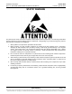
Installation Instructions Spec. No. 582140000 (Models 802NLDB, 802NLEB and 802NL-B) Section 5876 Issue AT, April 26, 2013 STATIC WARNING The printed circuit cards used in this equipment contain static sensitive components. The warnings listed below must be observed to prevent damage to these components. Disregarding any of these warnings may result in personal injury or damage to the equipment. 1. Strictly adhere to the procedures provided in this document. 2.
Section 5876 Issue AT, April 26, 2013 Installation Instructions Spec. No. 582140000 (Models 802NLDB, 802NLEB and 802NL-B) This Page Intentionally Left Blank Page 2 of 2 Static Warning This document is property of Emerson Network Power, Energy Systems, North America, Inc. and contains confidential and proprietary information owned by Emerson Network Power, Energy Systems, North America, Inc.
Installation Instructions Spec. No. 582140000 (Models 802NLDB, 802NLEB and 802NL-B) Section 5876 Issue AT, April 26, 2013 FCC INFORMATION The MCA Interface Modem Option (if installed) has been granted a registration number by the Federal Communications Commission, under Part 68 rules and regulations for direct connection to the telephone lines.
Section 5876 Issue AT, April 26, 2013 Installation Instructions Spec. No. 582140000 (Models 802NLDB, 802NLEB and 802NL-B) This Page Intentionally Left Blank Page 2 of 2 FCC Information This document is property of Emerson Network Power, Energy Systems, North America, Inc. and contains confidential and proprietary information owned by Emerson Network Power, Energy Systems, North America, Inc.
Installation Instructions Spec. No. 582140000 (Models 802NLDB, 802NLEB and 802NL-B) Section 5876 Issue AT, April 26, 2013 TABLE OF CONTENTS CONTENTS PAGE CHAPTER 1 GENERAL INFORMATION AND INSTALLATION CHECKLIST ..................... 1-1 Preface ............................................................................................................................................................. 1-1 Installation Acceptance Checklist ...................................................................
Section 5876 Issue AT, April 26, 2013 Installation Instructions Spec. No. 582140000 (Models 802NLDB, 802NLEB and 802NL-B) CHAPTER 4 MAKING ELECTRICAL CONNECTIONS ......................................................... 4-1 Observe the Following Admonishments .......................................................................................................... 4-2 Wiring Considerations .....................................................................................................................
Installation Instructions Spec. No. 582140000 (Models 802NLDB, 802NLEB and 802NL-B) Section 5876 Issue AT, April 26, 2013 CHAPTER 5 INSTALLING THE RECTIFIERS AND INITIALLY STARTING THE POWER SYSTEM .................................................................................................................. 5-1 Installing the Rectifiers .....................................................................................................................................
Section 5876 Issue AT, April 26, 2013 Installation Instructions Spec. No. 582140000 (Models 802NLDB, 802NLEB and 802NL-B) This Page Intentionally Left Blank Page iv Table of Contents This document is property of Emerson Network Power, Energy Systems, North America, Inc. and contains confidential and proprietary information owned by Emerson Network Power, Energy Systems, North America, Inc.
Installation Instructions Spec. No. 582140000 (Models 802NLDB, 802NLEB and 802NL-B) Section 5876 Issue AT, April 26, 2013 CHAPTER 1 GENERAL INFORMATION AND INSTALLATION CHECKLIST TABLE OF CONTENTS Preface .................................................................................................................... 1-1 Installation Acceptance Checklist ............................................................................
Section 5876 Issue AT, April 26, 2013 Installation Instructions Spec. No. 582140000 (Models 802NLDB, 802NLEB and 802NL-B) Chapter 3.
Installation Instructions Spec. No.
Section 5876 Issue AT, April 26, 2013 Installation Instructions Spec. No. 582140000 (Models 802NLDB, 802NLEB and 802NL-B) This Page Left Intentionally Blank Page 1-4 Chapter 1. General Information and Installation Checklist This document is property of Emerson Network Power, Energy Systems, North America, Inc. and contains confidential and proprietary information owned by Emerson Network Power, Energy Systems, North America, Inc.
Installation Instructions Spec. No. 582140000 (Models 802NLDB, 802NLEB and 802NL-B) Section 5876 Issue AT, April 26, 2013 CHAPTER 2 PLACING THE BAYS AND INSTALLING INTERNAL/EXTERNAL BUSBARS TABLE OF CONTENTS General Requirements .................................................................................................... 2-2 Placing and Securing List 1 and List 11 Power/Distribution Bays (without PDSC) ......... 2-3 Placing and Securing List 2 and List 12 Power/Distribution Bays (with PDSC) .......
Section 5876 Issue AT, April 26, 2013 Installation Instructions Spec. No. 582140000 (Models 802NLDB, 802NLEB and 802NL-B) GENERAL REQUIREMENTS Page 2-2 • The installer should be familiar with the installation requirements and techniques to be used in securing the bay(s) to the floor. • This product is intended only for installation in a Restricted Access Location on or above a non-combustible surface.
Installation Instructions Spec. No. 582140000 (Models 802NLDB, 802NLEB and 802NL-B) Section 5876 Issue AT, April 26, 2013 PLACING AND SECURING LIST 1 AND LIST 11 POWER/DISTRIBUTION BAYS (WITHOUT PDSC) Note: If you are installing List 2 and List 12 bays (with List 30, 31, or 32 PDSC), skip this procedure and refer to “Placing and Securing List 2 and List 12 Power/Distribution Bays (with PDSC)". • PDSC = AC Input 'Power Distribution Service Cabinet'.
Section 5876 Issue AT, April 26, 2013 Installation Instructions Spec. No. 582140000 (Models 802NLDB, 802NLEB and 802NL-B) Note: A ground washer is an internal-external tooth, dish-type lock washer. When installing ground washers, ensure that the ground washer is oriented so that the teeth dig into the paint on the metal part the ground washer is secured to (concave side faces the metal part). 4) Install shims between bottom of each bay and the floor as required to distribute floor loading.
Installation Instructions Spec. No. 582140000 (Models 802NLDB, 802NLEB and 802NL-B) Section 5876 Issue AT, April 26, 2013 PLACING AND SECURING LIST 2 AND LIST 12 POWER/DISTRIBUTION BAYS (WITH PDSC) Note: If you are installing List 1 and List 11 Bays (without List 30, 31, or 32 PDSC), skip this procedure and refer to “Placing and Securing List 1 and List 11 Power/Distribution Bays (without PDSC)". • PDSC = AC Input 'Power Distribution Service Cabinet'.
Section 5876 Issue AT, April 26, 2013 Installation Instructions Spec. No. 582140000 (Models 802NLDB, 802NLEB and 802NL-B) 6) Remove the rear upper cover panel from each PDSC. This cover panel will be re-installed after all mounting and electrical connection procedures have been completed.. To do so: Loosen the screws securing the cover panel. Lift the cover panel until the screw heads clear the keyhole slots. Remove the cover panel.
Installation Instructions Spec. No. 582140000 (Models 802NLDB, 802NLEB and 802NL-B) Section 5876 Issue AT, April 26, 2013 PLACING AND SECURING LIST 3, 4, 5, 13, 14, AND 15 POWER ONLY BAYS • Figure 2-1 provides a floor hole drilling pattern. • Bays are typically placed next to each other and bolted together. Refer to the previous Section, GENERAL REQUIREMENTS, for bay line-up recommendations.
Section 5876 Issue AT, April 26, 2013 Installation Instructions Spec. No. 582140000 (Models 802NLDB, 802NLEB and 802NL-B) 9) If the outside sides of the end bays do not have side cover panels, install them now (two per side). Note that ground washers are used with each screw securing the side cover panels. a) Install the rear-most side cover panel as follows: Insert tabs at front of cover panel into slots in bay. Pivot cover panel into position against side of bay.
Installation Instructions Spec. No. 582140000 (Models 802NLDB, 802NLEB and 802NL-B) Section 5876 Issue AT, April 26, 2013 PLACING AND SECURING LIST 16 DISTRIBUTION ONLY BAYS • Figure 2-3 provides List 16 Distribution Only Bay hole drilling patterns. • Bays are typically placed next to each other and bolted together. Refer to the previous Section, GENERAL REQUIREMENTS, for bay line-up recommendations.
Section 5876 Issue AT, April 26, 2013 Installation Instructions Spec. No. 582140000 (Models 802NLDB, 802NLEB and 802NL-B) 0.750 X 2.000 SLOT (4 PLACES) 3/8-16 Floor Leveling Bolts 3.44 30.00 24.12 2.44 19.62 24.00 2.19 FRONT 2.19 Floor Hole Drilling Pattern Power/Distribution Bay Figure 2-1 Floor Mounting Hole Dimensions (Primary and Secondary Power/Distribution Bays without PDSC) (Power Only Bays Have the Same Hole Pattern) (all dimensions in inches) Page 2-10 Chapter 2.
Installation Instructions Spec. No. 582140000 (Models 802NLDB, 802NLEB and 802NL-B) AC POWER DISTRIBUTION SERVICE CABINET 0.750 X 2.000 SLOT (4 PLACES) POWER/ DISTRIBUTION BAY 3/8-16 Floor Leveling Bolts 2.11 5.63 9.85 2.11 Section 5876 Issue AT, April 26, 2013 3/8-16 Floor Leveling Bolts 2.19 0.750 X 2.000 SLOT (4 PLACES) 3.44 30.00 24.12 2.44 2.19 19.62 24.
Section 5876 Issue AT, April 26, 2013 Installation Instructions Spec. No. 582140000 (Models 802NLDB, 802NLEB and 802NL-B) 3/8-16 Welded Nut (4) 31.375 27.625 25.875 23.250 19.500 26.625 19.500 24.000 30.000 25.375 3.063 1.750 1.875 2.750 4.063 5.937 0.812 Dia. (8 PLACES) Front Figure 2-3 Floor Mounting Hole Dimensions - Distribution Only Bay (all dimensions in inches) Page 2-12 Chapter 2.
Installation Instructions Spec. No. 582140000 (Models 802NLDB, 802NLEB and 802NL-B) Section 5876 Issue AT, April 26, 2013 PCU Mounting Position Blank Cover Panels Figure 2-4 Removing Rectifier Mounting Position Blank Cover Panels from Power/Distribution Bay Chapter 2. Placing the Bays and Installing Internal/External Busbars Page 2-13 This document is property of Emerson Network Power, Energy Systems, North America, Inc.
Section 5876 Issue AT, April 26, 2013 Installation Instructions Spec. No. 582140000 (Models 802NLDB, 802NLEB and 802NL-B) Rear Cover Panels Figure 2-5 Removing Rear Cover Panels from Power/Distribution Bay Page 2-14 Chapter 2. Placing the Bays and Installing Internal/External Busbars This document is property of Emerson Network Power, Energy Systems, North America, Inc. and contains confidential and proprietary information owned by Emerson Network Power, Energy Systems, North America, Inc.
Installation Instructions Spec. No. 582140000 (Models 802NLDB, 802NLEB and 802NL-B) Section 5876 Issue AT, April 26, 2013 Side Cover Panels TABS Remove/Install Screws through Front of Bay at these Points Remove/Install Screws through Rear of Bay at these Points Figure 2-6 Removing Side Cover Panels from Power/Distribution Bay Chapter 2. Placing the Bays and Installing Internal/External Busbars Page 2-15 This document is property of Emerson Network Power, Energy Systems, North America, Inc.
Section 5876 Issue AT, April 26, 2013 Installation Instructions Spec. No. 582140000 (Models 802NLDB, 802NLEB and 802NL-B) Front Cover Panel Rear Upper Cover Panel Remove Plug-Button on all but End Cabinet Rear Lower Cover Panel Figure 2-7 Removing Front and Rear Cover Panels, and Plug-Button from PDSC (AC Input 'Power Distribution Service Cabinet') Page 2-16 Chapter 2.
Installation Instructions Spec. No.
Section 5876 Issue AT, April 26, 2013 Installation Instructions Spec. No.
Installation Instructions Spec. No. 582140000 (Models 802NLDB, 802NLEB and 802NL-B) Section 5876 Issue AT, April 26, 2013 INSTALLING POWER/DISTRIBUTION BAY TO POWER/DISTRIBUTION BAY NEGATIVE AND POSITIVE BUSBAR LINKS Note: Refer to the next procedure to connect the newer style bay to an existing older style bay. Note: Apply electrical anti-oxidation compound to mating surfaces of busbars before connecting together.
Section 5876 Issue AT, April 26, 2013 Installation Instructions Spec. No. 582140000 (Models 802NLDB, 802NLEB and 802NL-B) POSITIVE BUSBAR LINK 3/8-16 x 1-1/2" Bolt 3/8" Belleville Lock Washer 3/8" Belleville Lock Washer (concave side of Belleville Lock Washers face each other) 3/8” Hardened Flat Washer (10 Places per Busbar) NEGATIVE BUSBAR LINK Slide Busbar Links Under Bays' Upright Channels. Use Bolt Holes as Shown in Illustration. Torque to 180 in-lbs.
Installation Instructions Spec. No. 582140000 (Models 802NLDB, 802NLEB and 802NL-B) Section 5876 Issue AT, April 26, 2013 POSITIVE BUSBAR LINK 3/8-16 x 1-1/2" Bolt 3/8" Belleville Lock Washer 3/8" Belleville Lock Washer (concave side of Belleville Lock Washers face each other) 3/8” Hardened Flat Washer (10 Places per Busbar) NEGATIVE BUSBAR LINK Slide Busbar Links Under Bays' Upright Channels. Use Bolt Holes as Shown in Illustration. Torque to 180 in-lbs.
Section 5876 Issue AT, April 26, 2013 Installation Instructions Spec. No. 582140000 (Models 802NLDB, 802NLEB and 802NL-B) INSTALLING POWER/DISTRIBUTION BAY TO POWER/DISTRIBUTION BAY NEGATIVE AND POSITIVE BUSBAR LINKS (NEWER STYLE BAY TO AN EXISTING OLDER STYLE BAY) Note: Apply electrical anti-oxidation compound to mating surfaces of busbars before connecting together.
Installation Instructions Spec. No. 582140000 (Models 802NLDB, 802NLEB and 802NL-B) Section 5876 Issue AT, April 26, 2013 Newer Style Bay Existing Older Style Bay Newer Style Bay Existing Older Style Bay POSITIVE BUSBAR LINK 3/8-16 x 1-1/2" Bolt 3/8" Belleville Lock Washer 3/8" Belleville Lock Washer (concave side of Belleville Lock Washers face each other) 3/8” Hardened Flat Washer NEGATIVE BUSBAR LINK Newer Style Bay side, use bolt holes as shown in illustration. List 1 and 11 shown.
Section 5876 Issue AT, April 26, 2013 Installation Instructions Spec. No. 582140000 (Models 802NLDB, 802NLEB and 802NL-B) CONNECTING POWER/DISTRIBUTION BAY RECTIFIER MOUNTING POSITION AC INPUT CONNECTORS TO PDSC (LISTS 2 AND 12 ONLY) Procedure 1) Refer to Figure 2-13, and feed the wires from the Rectifier Mounting Position AC Input Connectors located in a Power/Distribution Bay through the side of the Rectifier Mounting Position AC Input Cover and into the PDSC.
Installation Instructions Spec. No.
Section 5876 Issue AT, April 26, 2013 Installation Instructions Spec. No. 582140000 (Models 802NLDB, 802NLEB and 802NL-B) STEP 1 Install “Main Positive Busbar” onto Bay’s Positive Busbar. Hand-tighten hardware. (1) Main Positive Busbar, P/N 554877 Note: Apply Electrical Anti-Oxidation Compound to Busbar Mating Surfaces. (12) 3/8” Flat Washer, P/N 214204100 (12) 3/8” Belleville Washer, P/N 214825000 (12) 3/8-16 Hex Nut, P/N 228567100 Hand-tighten.
Installation Instructions Spec. No. 582140000 (Models 802NLDB, 802NLEB and 802NL-B) Section 5876 Issue AT, April 26, 2013 STEP 2 Install “Support Bar” and “Related Hardware” onto Top of Bay. (2) Threaded Insulator, P/N 245857200 Torque to 715 In-lbs. (2) Support Bar Clip, P/N 351322300 (2) Support Bar, P/N 237790100 (2) Support Bar Clip, P/N 351322300 (2) 5/8” Lock Washer, P/N 215111800 (2) 5/8” Hex Nut, P/N 228580900 Leave 1/4” Space Between Bottom of Nut and Top of Bay.
Section 5876 Issue AT, April 26, 2013 Installation Instructions Spec. No. 582140000 (Models 802NLDB, 802NLEB and 802NL-B) STEP 3 Install “Main Negative Busbar” onto Bay’s Negative Busbar. Hand-tighten hardware. (1) Main Negative Busbar, P/N 554875 Note: Apply Electrical Anti-Oxidation Compound to Busbar Mating Surfaces.
Installation Instructions Spec. No. 582140000 (Models 802NLDB, 802NLEB and 802NL-B) Section 5876 Issue AT, April 26, 2013 STEP 4 Install “Horizontal Landing Negative Busbar” onto “Main Negative Busbar”. Torque to 180 in-lbs. (6) 3/8-16 x 1-1/4” Bolt, P/N 227646800 (6) 3/8” Belleville Washer, P/N 214825000 (6) 3/8" Flat Washer, P/N 214204100 Note: Concave Side of Belleville Washer Faces Busbar, Convex Side Faces Bolt Head. Belleville Washer install between Bolt Head and Flat Washer.
Section 5876 Issue AT, April 26, 2013 Installation Instructions Spec. No. 582140000 (Models 802NLDB, 802NLEB and 802NL-B) STEP 5 Install "Threaded Insulators" onto "Horizontal Landing Negative Busbar".
Installation Instructions Spec. No. 582140000 (Models 802NLDB, 802NLEB and 802NL-B) Section 5876 Issue AT, April 26, 2013 STEP 6 Install "Horizontal Landing Positive Busbar" onto "Main Positive Busbar". (2) 5/8-11 x 1" Bolt, P/N 227655100 Torque to 715 in-lbs. (2) 5/8" Lock Washer, P/N 215111800 (2) 5/8" Flat Washer, P/N 214201300 (1) Horizontal Landing Positive Busbar, P/N 514436 Note: Apply Electrical Anti-Oxidation Compound to Busbar Mating Surfaces. Torque to 180 in-lbs.
Section 5876 Issue AT, April 26, 2013 Installation Instructions Spec. No. 582140000 (Models 802NLDB, 802NLEB and 802NL-B) STEP 7 Final Torque Rear Top of Bay Torque these connections to 180 in-lbs (20 places). Figure 2-20 Power/Distribution Bay External Top-Mount Horizontal Busbar Assembly (P/N 554873) Assembly Procedure Step 7 Page 2-32 Chapter 2. Placing the Bays and Installing Internal/External Busbars This document is property of Emerson Network Power, Energy Systems, North America, Inc.
Installation Instructions Spec. No. 582140000 (Models 802NLDB, 802NLEB and 802NL-B) Section 5876 Issue AT, April 26, 2013 Assembled View from Rear of Bay Assembled View from Front of Bay Figure 2-21 Power/Distribution Bay External Top-Mount Horizontal Busbar Assembly (P/N 554873) Assembled Views Chapter 2. Placing the Bays and Installing Internal/External Busbars Page 2-33 This document is property of Emerson Network Power, Energy Systems, North America, Inc.
Section 5876 Issue AT, April 26, 2013 Installation Instructions Spec. No. 582140000 (Models 802NLDB, 802NLEB and 802NL-B) INSTALLING OPTIONAL POWER/DISTRIBUTION BAY BUSBAR SHIELD KIT, P/N 528482 (IF FURNISHED) Tools and Material Required to Install the Busbar Assembly a) 9/16" Wrench (for 3/8" Hardware) b) Torque Wrench Installation Procedure Danger: Before performing this procedure, ensure that the Power/Distribution Bay is COMPLETELY DISCONNECTED from all power sources.
Installation Instructions Spec. No.
Section 5876 Issue AT, April 26, 2013 Installation Instructions Spec. No. 582140000 (Models 802NLDB, 802NLEB and 802NL-B) STEP 1 Install "Threaded Insulators". (1) Threaded Insulator, P/N 245857200 Hand-Tighten (1) 5/8-11 x 1-1/4" Threaded Rod, P/N 334315700 (1) Threaded Insulator, P/N 245857200 Previously Assembled Kit P/N 554873 Rear Top of Bay (1) 5/8" Flat Washer, P/N 214201300 (1) 5/8" Lock Washer, P/N 215111800 (1) 5/8-11 x 1" Bolt, P/N 227655100 Torque to 715 in-lbs.
Installation Instructions Spec. No. 582140000 (Models 802NLDB, 802NLEB and 802NL-B) Section 5876 Issue AT, April 26, 2013 STEP 2A Install "Busbars". (see Step 2B for Bolt Hole Identification) (see Step 2C for Assembled View) * Use "Spacer Busbars" or "Spacer Insulators" on end bays or stand-alone bays. For multiple bays, 'sandwich' busbars of adjacent "Busbar Assemblies" together. Note: Apply Electrical Anti-Oxidation Compound to all Busbar Mating Surfaces.
Section 5876 Issue AT, April 26, 2013 Installation Instructions Spec. No. 582140000 (Models 802NLDB, 802NLEB and 802NL-B) STEP 2B Install "Busbars". (Bolt Hole Identification) Figure 2-25 Power/Distribution Bay External Top-Mount Ground (Load Return) Busbar Assembly (P/N 514688 or 514689) Assembly Procedure Step 2B Page 2-38 Chapter 2. Placing the Bays and Installing Internal/External Busbars This document is property of Emerson Network Power, Energy Systems, North America, Inc.
Installation Instructions Spec. No. 582140000 (Models 802NLDB, 802NLEB and 802NL-B) Section 5876 Issue AT, April 26, 2013 STEP 2C Install "Busbars". (Assembled Views) Spacer Busbars or Spacer Insulators Installed Previously Assembled Kit P/N 554873 Assembled Views No Spacer Busbars or Spacer Insulators. Busbars of Adjacent Assemblies 'Sandwich' and Bolted Together.
Section 5876 Issue AT, April 26, 2013 Installation Instructions Spec. No. 582140000 (Models 802NLDB, 802NLEB and 802NL-B) STEP 3 Install "Cover" Mounting Standoffs. (2) Standoff, P/N 117843 (2) 1/4" Flat Washer, P/N 214110100 (2) 1/4" Lock Washer, P/N 215111100 (2) 1/4-20 x 1/2" Bolt, P/N 227640200 Torque to 84 in-lbs.
Installation Instructions Spec. No. 582140000 (Models 802NLDB, 802NLEB and 802NL-B) Section 5876 Issue AT, April 26, 2013 STEP 4 (2) 1/4-20 x 1/2" Bolt, P/N 227640200 (2) 1/4" Lock Washer, P/N 215111100 Install "Covers". (2) 1/4" Flat Washer, P/N 214110100 P/N 514520 Torque to 45 in-lbs.
Section 5876 Issue AT, April 26, 2013 Installation Instructions Spec. No. 582140000 (Models 802NLDB, 802NLEB and 802NL-B) Assembled Views P/N 514688 Assembled Views P/N 514689 Assembled Views P/N 514690 Assembled Views P/N 514691 Figure 2-29 Power/Distribution Bay External Top-Mount Ground (Load Return) Busbar Assembly (P/N 514688, 514689, 514690, and 514691) Assembled Views Page 2-42 Chapter 2.
Installation Instructions Spec. No. 582140000 (Models 802NLDB, 802NLEB and 802NL-B) Section 5876 Issue AT, April 26, 2013 P/N 514688 or 514689 P/N 554873 Front View Busbar Assembly Assembled on Top of Bays (List 1 and 11 Bays) P/N 514690 or 514691 P/N 554873 Figure 2-30 Power/Distribution Bay External Top-Mount Ground (Load Return) Busbar Assembly (P/N 514688, 514689, 514690, and 514691) Assembled on Top of Bays Chapter 2.
Section 5876 Issue AT, April 26, 2013 Installation Instructions Spec. No. 582140000 (Models 802NLDB, 802NLEB and 802NL-B) Installation Procedure for P/N 514690 and 514691 Danger: Before performing this procedure, ensure that the Power/Distribution Bay is COMPLETELY DISCONNECTED from all power sources. Note: Apply electrical anti-oxidation compound to mating surfaces of busbars before connecting together. Assemble the Busbar Kit to the top of the bays as shown in Figure 2-31 through Figure 2-36.
Installation Instructions Spec. No. 582140000 (Models 802NLDB, 802NLEB and 802NL-B) Section 5876 Issue AT, April 26, 2013 STEP 1 Install "Threaded Insulators". (1) Threaded Insulator, P/N 245857200 Hand-Tighten (1) 5/8-11 x 1-1/4" Threaded Rod, P/N 334315700 (1) Threaded Insulator, P/N 245857200 Previously Assembled Kit P/N 554873 Rear Top of Bay (1) 5/8" Flat Washer, P/N 214201300 (1) 5/8" Lock Washer, P/N 215111800 (1) 5/8-11 x 1" Bolt, P/N 227655100 Torque to 715 in-lbs.
Section 5876 Issue AT, April 26, 2013 Installation Instructions Spec. No. 582140000 (Models 802NLDB, 802NLEB and 802NL-B) STEP 2A Install "Busbars". (see Step 2B for Bolt Hole Identification) (see Step 2C for Assembled View) * Use "Spacer Busbars" or "Spacer Insulators" Note: Apply Electrical Anti-Oxidation on end bays or stand-alone bays. For multiple Compound to all Busbar bays, use "Spacer Busbars" and move out Mating Surfaces. to 'bridge' between busbars of both Assemblies (see Assembled View).
Installation Instructions Spec. No. 582140000 (Models 802NLDB, 802NLEB and 802NL-B) Section 5876 Issue AT, April 26, 2013 STEP 2B Install "Busbars". (Bolt Hole Identification) * Use "Spacer Busbars" or "Spacer Insulators" on end bays or stand-alone bays. For multiple bays, use "Spacer Busbars" and move out to 'bridge' between busbars of both Assemblies (see Assembled View).
Section 5876 Issue AT, April 26, 2013 Installation Instructions Spec. No. 582140000 (Models 802NLDB, 802NLEB and 802NL-B) Spacer Busbars STEP 2C or Spacer Insulators Install "Busbars". Installed (Assembled Views) Previously Assembled Kit P/N 554873 Assembled Views * Use "Spacer Busbars" or "Spacer Insulators" on end bays or stand-alone bays. For multiple bays, use "Spacer Busbars" and move out to 'bridge' between busbars of both Assemblies.
Installation Instructions Spec. No. 582140000 (Models 802NLDB, 802NLEB and 802NL-B) Section 5876 Issue AT, April 26, 2013 STEP 3 Install "Cover" Mounting Standoffs. (2) Standoff, P/N 117843 (2) 1/4" Flat Washer, P/N 214110100 (2) 1/4" Lock Washer, P/N 215111100 (2) 1/4-20 x 1/2" Bolt, P/N 227640200 Torque to 45 in-lbs.
Section 5876 Issue AT, April 26, 2013 Installation Instructions Spec. No. 582140000 (Models 802NLDB, 802NLEB and 802NL-B) DO NOT PERFORM THIS STEP if you are going to install "Load Return Lug Extension Busbar Assembly" P/N 514543 STEP 4 Install "Covers". (2) 1/4-20 x 1/2" Bolt, P/N 227640200 (2) 1/4" Lock Washer, P/N 215111100 (2) 1/4" Flat Washer, P/N 214110100 Torque to 45 in-lbs.
Installation Instructions Spec. No.
Section 5876 Issue AT, April 26, 2013 Installation Instructions Spec. No. 582140000 (Models 802NLDB, 802NLEB and 802NL-B) STEP 1A Remove any previously installed bolts from these four locations Install "Load Return Lug Extension Busbar" (List 1 and 11 Bays). Note: Apply Electrical Anti-Oxidation Compound to all Busbar Mating Surfaces. (8*) 3/8-16 x 3" Bolt, P/N 227647800 (1*) Busbar, P/N 514542 Torque to 180 in-lbs.
Installation Instructions Spec. No. 582140000 (Models 802NLDB, 802NLEB and 802NL-B) Section 5876 Issue AT, April 26, 2013 PROCEDURE PROVIDED FOR REFERENCE ONLY, INSTALL BOLTS AS LUGS ARE INSTALLED TO BUSBAR STEP 2A Install "Lug Mounting Bolts" (List 1 and 11 Bays). (24*) 3/8-16 x 1-1/4" Bolt, P/N 227646800 * Quantities are per Kit, two Kits shown in Illustrations.
Section 5876 Issue AT, April 26, 2013 Installation Instructions Spec. No. 582140000 (Models 802NLDB, 802NLEB and 802NL-B) STEP 3A Install "Covers" (List 1 and 11 Bays). (2*) 10-32 Lock Nut, P/N 104564 Rear Top of Bay (2*) 10-32 x 3/4" Tap Screw, P/N 218706500 * Parts are from the P/N 514688 or 514689 Kit. Quantities are per Kit, two Kits shown in Illustrations.
Installation Instructions Spec. No. 582140000 (Models 802NLDB, 802NLEB and 802NL-B) Section 5876 Issue AT, April 26, 2013 STEP 1B Note: Apply Electrical Anti-Oxidation Compound to all Busbar Mating Surfaces. (1*) Busbar, P/N 514542 Install "Load Return Lug Extension Busbar" (List 2 and 12 Bays E/W List 30 or 31 PDSC). (8*) 3/8-16 x 3" Bolt, P/N 227647800 Torque to 180 in-lbs.
Section 5876 Issue AT, April 26, 2013 Installation Instructions Spec. No. 582140000 (Models 802NLDB, 802NLEB and 802NL-B) STEP 2B Install "Lug Mounting Bolts" (List 2 and 12 Bays E/W List 30 or 31 PDSC). PROCEDURE PROVIDED FOR REFERENCE ONLY, INSTALL BOLTS AS LUGS ARE INSTALLED TO BUSBAR * Quantities are per Kit, two Kits shown in Illustrations.
Installation Instructions Spec. No. 582140000 (Models 802NLDB, 802NLEB and 802NL-B) Section 5876 Issue AT, April 26, 2013 STEP 3B Install "Covers" (List 2 and 12 Bays E/W List 30 or 31 PDSC). (2*) 10-32 Lock Nut, P/N 104564 Rear Top of Bay (2*) 10-32 x 3/4" Tap Screw, P/N 218706500 * Parts are from the P/N 514690 or 514691 Kit. Quantities are per Kit, two Kits shown in Illustrations.
Section 5876 Issue AT, April 26, 2013 Installation Instructions Spec. No.
Installation Instructions Spec. No. 582140000 (Models 802NLDB, 802NLEB and 802NL-B) Section 5876 Issue AT, April 26, 2013 Figure 2-44 Power/Distribution Bay Load Return Lug Extension Busbar Assembly (P/N 514543) Assembled on Top of Bays Chapter 2. Placing the Bays and Installing Internal/External Busbars Page 2-59 This document is property of Emerson Network Power, Energy Systems, North America, Inc.
Section 5876 Issue AT, April 26, 2013 Installation Instructions Spec. No.
Installation Instructions Spec. No. 582140000 (Models 802NLDB, 802NLEB and 802NL-B) Section 5876 Issue AT, April 26, 2013 STEP 1 Install “Main Positive Busbar” onto Bay Positive Busbar. (1) Main Positive Busbar, P/N 554877 Note: Apply Electrical Anti-Oxidation Compound to busbar mating surfaces. Rear Top of Bay Do the following first before assembly: 1. Remove 552402 (1) and 116638 (4) from Bay. 2. Mount 554880 to the 554877 with 116638 (3).
Section 5876 Issue AT, April 26, 2013 Installation Instructions Spec. No. 582140000 (Models 802NLDB, 802NLEB and 802NL-B) STEP 2 Install “Support Bar” and “Related Hardware” onto Top of Bay. (2) Threaded Insulator, P/N 245857200 Torque to 715 in-lbs. (2) Support Bar Clip, P/N 351322300 (2) Support Bar, P/N 237790100 (2) Support Bar Clip, P/N 351322300 (2) 5/8” Lock Washer, P/N 215111800 (2) 5/8” Hex Nut, P/N 228580900 Leave 1/2” space between bottom of nut and top of bay.
Installation Instructions Spec. No. 582140000 (Models 802NLDB, 802NLEB and 802NL-B) Section 5876 Issue AT, April 26, 2013 STEP 3 Install “Main Negative Busbar” onto Bay Negative Busbar. Rear Top of Bay (1) Main Negative Busbar, P/N 554875 Note: Apply Electrical Anti-Oxidation Compound to busbar mating services. (8) 3/8” Flat Washer, P/N 214204100 (8) 3/8” Belleville Washer, P/N 214825000 (8) 3/8-16 Hex Nut, P/N 228567100 Hand-tighten only.
Section 5876 Issue AT, April 26, 2013 Installation Instructions Spec. No. 582140000 (Models 802NLDB, 802NLEB and 802NL-B) STEP 4 Install “Vertical Landing Negative Busbar” onto “Main Negative Busbar”. (6) 3/8-16 x 1-1/4” Bolt, P/N 227646800 Torque to 180 in-lbs. (6) 3/8” Belleville Washer, P/N 214825000 (6) 3/8” Flat Washer, P/N 214204100 Note: Concave side of Belleville washer faces busbar; convex side faces bolt head.
Installation Instructions Spec. No. 582140000 (Models 802NLDB, 802NLEB and 802NL-B) Section 5876 Issue AT, April 26, 2013 STEP 5 Install “Threaded Insulators” onto “Vertical Landing Negative Busbar”. (2) Threaded Insulator, P/N 245857200 Hand-tighten only. (2) 5/8-11 x 1-1/4” Threaded Rod, P/N 334315700 (2) Threaded Insulator, P/N 245857200 Hand-tighten only.
Section 5876 Issue AT, April 26, 2013 Installation Instructions Spec. No. 582140000 (Models 802NLDB, 802NLEB and 802NL-B) STEP 6 Install “Vertical Landing Positive Busbar” onto “Main Positive Busbar”. (6) 3/8-16 x 1-1/4” Bolt, P/N 227646800 Torque to 180 in-lbs. (6) 3/8” Belleville Washer, P/N 214825000 (6) 3/8” Flat Washer, P/N 214204100 (2) 5/8-11 x 1” Bolt, P/N 227655100 Torque to 715 in-lbs.
Installation Instructions Spec. No. 582140000 (Models 802NLDB, 802NLEB and 802NL-B) Section 5876 Issue AT, April 26, 2013 STEP 7 Final Torque Rear Top of Bay Torque these connections to 180 in-lbs (20 places). Figure 2-51 Power/Distribution Bay External Top-Mount Vertical Busbar Assembly (P/N 554874) Assembly Procedure Step 7 Chapter 2. Placing the Bays and Installing Internal/External Busbars Page 2-67 This document is property of Emerson Network Power, Energy Systems, North America, Inc.
Section 5876 Issue AT, April 26, 2013 Installation Instructions Spec. No. 582140000 (Models 802NLDB, 802NLEB and 802NL-B) STEP 8 Install Shield (2) Standoff Insulator, P/N 117843 (1) Plastic Shield, P/N 548002 (4) 14-20 x 3/8” Pan Head Tap Screw, P/N 218708200 Assembled View Figure 2-52 Power/Distribution Bay External Top-Mount Vertical Busbar Assembly (P/N 554874) Assembly Procedure Step 8 Page 2-68 Chapter 2.
Installation Instructions Spec. No. 582140000 (Models 802NLDB, 802NLEB and 802NL-B) Section 5876 Issue AT, April 26, 2013 CHAPTER 3 INSTALLING DISTRIBUTION DEVICES AND MCA/LMS CIRCUIT CARDS TABLE OF CONTENTS Installing Distribution Fuses and Circuit Breakers ........................................................... 3-1 Installing 218 Circuit Breakers, TPL Fuseholders, and Bullet Nose-Type Device Mounting Assemblies into Power/Distribution Bays .....................................
Section 5876 Issue AT, April 26, 2013 Installation Instructions Spec. No. 582140000 (Models 802NLDB, 802NLEB and 802NL-B) and Figure 3-6 for load lug adapter selection. Hardware build-up is 1/4 inch flat washer, 1/4 inch lock washer, and 1/4-20 nut. Torque to 84 in-lbs. Note that Bullet Nose-Type devices do not require load lug adapter plates.
Installation Instructions Spec. No. 582140000 (Models 802NLDB, 802NLEB and 802NL-B) Section 5876 Issue AT, April 26, 2013 Installing TLS/TPS Fuses Refer to Figure 3-7 and Figure 3-8. Procedure 1) Orient the Bullet Nose-Type Fuseholder over its mounting position and firmly press to seat the bullet-type connectors. 2) Remove the fuseholder portion from the mounted fuseholder body by pulling it straight out. Install the TLS/TPS fuse into the fuseholder.
Section 5876 Issue AT, April 26, 2013 Installation Instructions Spec. No. 582140000 (Models 802NLDB, 802NLEB and 802NL-B) Flat Washer Lock Washer 1/4-20 Nut Torque to 84 in-lbs Distribution Device Top Mounting Studs Distr. Bus #1 Distribution Device Power System Connectors 1 12 13 Distribution Device Bottom Mounting Studs 24 Torque to 180 in-lbs Belleville Lock Washer 3/8-16 Nut Distr. Bus #2 25 36 37 Left Half Distr. Bus #1 and #2 Right Half Distr.
Installation Instructions Spec. No.
Section 5876 Issue AT, April 26, 2013 Installation Instructions Spec. No. 582140000 (Models 802NLDB, 802NLEB and 802NL-B) Figure 3-3 Installing 218 Circuit Breakers and TPL Fuseholders into Distribution Only Bays Page 3-6 Chapter 3. Installing Distribution Devices and MCA/LMS Circuit Cards This document is property of Emerson Network Power, Energy Systems, North America, Inc. and contains confidential and proprietary information owned by Emerson Network Power, Energy Systems, North America, Inc.
Installation Instructions Spec. No. 582140000 (Models 802NLDB, 802NLEB and 802NL-B) Section 5876 Issue AT, April 26, 2013 Rear View Rear View Rear cover panels removed in illustration for clarity.
Section 5876 Issue AT, April 26, 2013 Installation Instructions Spec. No.
Installation Instructions Spec. No. 582140000 (Models 802NLDB, 802NLEB and 802NL-B) Section 5876 Issue AT, April 26, 2013 Customer Supplied Lug (1) Spacer Busbar, P/N 528806 (2) 3/8-16 Hex Nut, P/N 228567100 (2) 3/8" Flat Washer, P/N 214204100 (1) 1/4-20 x 7/8" Bolt, P/N 227640500 (1) 1/4" Flat Washer, P/N 214110100 Torque to 84 in-lbs. Busbars P/O Dist. Bay Torque to 180 in-lbs.
Section 5876 Issue AT, April 26, 2013 Installation Instructions Spec. No. 582140000 (Models 802NLDB, 802NLEB and 802NL-B) Customer Supplied Lugs (4) 3/8-16 Hex Nut, P/N 228567100 (4) 3/8" Flat Washer, P/N 214204100 Busbars P/O Dist. Bay Torque to 180 in-lbs. (4) 3/8-16 Hex Nut, P/N 228567100 (4) 3/8" Flat Washer, P/N 214204100 (2) 1/4-20 x 5/8" Bolt, P/N 227640300 (2) 1/4" Lock Washer, P/N 215111100 (2) 1/4" Flat Washer, P/N 214110100 Torque to 84 in-lbs.
Installation Instructions Spec. No. 582140000 (Models 802NLDB, 802NLEB and 802NL-B) Section 5876 Issue AT, April 26, 2013 Customer Supplied Lugs Torque to 180 in-lbs. (8) 3/8-16 Hex Nut, P/N 228567100 (8) 3/8" Flat Washer, P/N 214204100 Busbars P/O Dist.
Section 5876 Issue AT, April 26, 2013 Installation Instructions Spec. No. 582140000 (Models 802NLDB, 802NLEB and 802NL-B) Lug Adapter Kits Distribution Only Bays Lug Adapter Kits Power/Distribution Bays 1.000" NO LUG ADAPTER KITS REQUIRED WHEN USED IN DISTRIBUTION ONLY BAYS 3/8" Clearance Holes Lug Adapter P/N 513700, Kit P/N 520891 (see Notes 1, 2, 3) Load Lug Adapter Plate for 1-Pole Devices Lug Adapter Kits Distribution Only Bays 1-Pole 218 Circuit Breakers Assemblies 3/8" Clearance Hole 1.
Installation Instructions Spec. No. 582140000 (Models 802NLDB, 802NLEB and 802NL-B) Section 5876 Issue AT, April 26, 2013 Lug Adapter Kits Power/Distribution Bays 1.000" Lug Adapter Kits Distribution Only Bays 2.000" 3/8" Clearance Holes Lug Adapter P/N 513702, Kit P/N 520893 (see Notes 1, 2, 3) 1.
Section 5876 Issue AT, April 26, 2013 Installation Instructions Spec. No. 582140000 (Models 802NLDB, 802NLEB and 802NL-B) TPL Fuse GMT-18/100A Alarm Fuse and GMT-X Safety Fuse Cover Fuseholder Assembly P/N 514403 Lug Adapter Kits Distribution Only Bays 3/8" Clearance Hole 1.000" Lug Adapter Kits Power/Distribution Bays 1.000" 3/8" Clearance Holes Lug Adapter P/N 513701, Kit P/N 520892 (see Notes 1, 2, 3) Load Lug Adapter Plate 2-Position Lug Adapter Kit P/N 529132 (see Notes 4, 6, 7, 8) Notes: 1.
Installation Instructions Spec. No. 582140000 (Models 802NLDB, 802NLEB and 802NL-B) Section 5876 Issue AT, April 26, 2013 TPL Fuse GMT-18/100A Alarm Fuse and GMT-X Safety Fuse Cover Fuseholder Assembly P/N 514404 Lug Adapter Kits Distribution Only Bays Lug Adapter Kits Power/Distribution Bays 1.000" 1.000" 2.
Section 5876 Issue AT, April 26, 2013 Installation Instructions Spec. No. 582140000 (Models 802NLDB, 802NLEB and 802NL-B) Fuseholder Assembly TPL Fuses Flat Washer Lock Washer Nut P/N 514403 P/N 514404 TPL Fuse Torque to 168 in-lbs GMT-18/100A Alarm Fuse & GMT-X Safety Fuse Cover Bullet Nose-Type Circuit Breakers Loosen (2) screws & lift retainer (removed here to show detail). Shorter side to the top. TLS/TPS Fuses Longer side to the bottom.
Installation Instructions Spec. No. 582140000 (Models 802NLDB, 802NLEB and 802NL-B) Section 5876 Issue AT, April 26, 2013 Note: Load leads are connected to load busbars. These busbars provide 1/4-20 threaded holes on 5/8” centers for installation of customer provided two-hole lugs. Customer must provide lug mounting bolts and additional hardware. Bolt length: 3/4”.
Section 5876 Issue AT, April 26, 2013 Installation Instructions Spec. No. 582140000 (Models 802NLDB, 802NLEB and 802NL-B) INSTALLING MCA AND LMS CIRCUIT CARDS Circuit Card Handling Warning: Before handling any circuit card, read and follow the instructions contained on the Static Warning Page located at the beginning of this manual. A static wrist strap grounded through a one megohm resistor should always be worn when handling the circuit cards.
Installation Instructions Spec. No. 582140000 (Models 802NLDB, 802NLEB and 802NL-B) Section 5876 Issue AT, April 26, 2013 6) When all circuit cards have been installed, slide the circuit card retaining angle up and secure by tightening the two screws. 7) When all circuit cards have been installed, remove the grounding wrist strap. 8) After all electrical connections are made, close the bay's front door. 9) Save several of the static protective bags that the circuit cards were shipped in.
Section 5876 Issue AT, April 26, 2013 Installation Instructions Spec. No. 582140000 (Models 802NLDB, 802NLEB and 802NL-B) Power/Distribution Bay Shown, Power Only Bay Similar SYSTEM MONITORING AND CONTROL SECTION Seven-Slot Card Cage for MCA circuit cards and/or LMS Input/Output (I/O) circuit cards. Note: MCA circuit cards can be installed in any position. LMS I/O circuit cards MUST be populated left to right, W/OUT skipping any slots.
Installation Instructions Spec. No. 582140000 (Models 802NLDB, 802NLEB and 802NL-B) Section 5876 Issue AT, April 26, 2013 Power/Distribution Bay Shown, Power Only Bay Similar MCA Customer Alarm Relay Circuit Card P/N 514348. MCA I/O Circuit Card P/N 524550 Install in any position in seven-slot card cage in any bay. Component side faces left as viewed from the front. Figure 3-10 Installing the MCA Circuit Card(s) (Power/Distribution Bay Shown, Power Only Bay Similar) Chapter 3.
Section 5876 Issue AT, April 26, 2013 Installation Instructions Spec. No. 582140000 (Models 802NLDB, 802NLEB and 802NL-B) This Page Intentionally Left Blank Page 3-22 Chapter 3. Installing Distribution Devices and MCA/LMS Circuit Cards This document is property of Emerson Network Power, Energy Systems, North America, Inc. and contains confidential and proprietary information owned by Emerson Network Power, Energy Systems, North America, Inc.
Installation Instructions Spec. No. 582140000 (Models 802NLDB, 802NLEB and 802NL-B) Section 5876 Issue AT, April 26, 2013 CHAPTER 4 MAKING ELECTRICAL CONNECTIONS TABLE OF CONTENTS Observe the Following Admonishments .......................................................................... 4-2 Wiring Considerations ..................................................................................................... 4-3 MCA Network Interconnections Between Bays .............................................
Section 5876 Issue AT, April 26, 2013 Installation Instructions Spec. No. 582140000 (Models 802NLDB, 802NLEB and 802NL-B) Connecting a 582140000 Main Power Bay to a 582121100 Power Bay and/or 582121900/582121901 Distribution Bay (MCA and LMS Interconnections) .......... 4-67 Connecting a 582140000 Main Power Bay to a Medium Vortex Power System when the MCA is located in the PCU Intelligence Shelf (MCA Interconnections).........................................................................................
Installation Instructions Spec. No. 582140000 (Models 802NLDB, 802NLEB and 802NL-B) Section 5876 Issue AT, April 26, 2013 WIRING CONSIDERATIONS For recommended wire sizes, crimp lugs, branch circuit protection, alarm relay contact ratings, and general wiring information and restrictions; refer to System Application Guide SAG582140000. The SAG can be accessed via the CD (Electronic Documentation Package) furnished with your system. Refer to drawing 031110100 for lug crimping information.
Section 5876 Issue AT, April 26, 2013 Installation Instructions Spec. No. 582140000 (Models 802NLDB, 802NLEB and 802NL-B) MCA NETWORK INTERCONNECTIONS BETWEEN BAYS An MCA Network cable must be installed between all bays comprising the system, as detailed in the following procedure. It is recommended to place the Primary Power/Distribution or Power Only Bay on the far right or far left end of the bay line-up, and to expand the system to the left or right of the Primary Power/Distribution or Power Only Bay.
Installation Instructions Spec. No. 582140000 (Models 802NLDB, 802NLEB and 802NL-B) Section 5876 Issue AT, April 26, 2013 line-up. It doesn't matter which connector you use on a Secondary Power/Distribution or Power Only Bay and Distribution Only Bay, or which order you connect Secondary Power/Distribution or Power Only Bays and Distribution Only Bays. Just remember, DO NOT use both connectors on the Primary Power/Distribution or Power Only Bay.
Section 5876 Issue AT, April 26, 2013 Installation Instructions Spec. No.
Installation Instructions Spec. No. 582140000 (Models 802NLDB, 802NLEB and 802NL-B) Section 5876 Issue AT, April 26, 2013 DISTRIBUTION ONLY BAY BAT RTN CONNECTION TO SYSTEM MONITORING AND CONTROL SECTION Procedure 1) Connect BAT RTN to the terminal indicated in Figure 4-2. Use 18-16 AWG wire for this connection.
Section 5876 Issue AT, April 26, 2013 Installation Instructions Spec. No. 582140000 (Models 802NLDB, 802NLEB and 802NL-B) Power/Distribution Bay Shown, Power Only Bay Similar SYSTEM MONITORING AND CONTROL SECTION External CAN BUS Port MCA Battery Charge Digital Temperature Compensation Probe Connector (Primary Bay Only) Battery Charge Digital Temperature Compensation Probe Figure 4-3 MCA TEMP Connector and MCA External CAN Bus Port Location Page 4-8 Chapter 4.
Installation Instructions Spec. No. 582140000 (Models 802NLDB, 802NLEB and 802NL-B) Section 5876 Issue AT, April 26, 2013 MCA EXTERNAL ALARM, REFERENCE, AND CONTROL CONNECTIONS AND MCA I/O CIRCUIT CARD CONNECTIONS Note: For recommended wire size and alarm relay contact ratings, refer to System Application Guide SAG582140000. The SAG can be accessed via the CD (Electronic Documentation Package) furnished with your system. Refer to Figure 4-4 for connector locations and pinouts.
Section 5876 Issue AT, April 26, 2013 Installation Instructions Spec. No. 582140000 (Models 802NLDB, 802NLEB and 802NL-B) c) With the Test loop closure still applied, apply the Emergency Stop loop closure. Verify MCA displays EMERGENCY STOP INPUT IS ON. Release the Emergency Stop loop closure. d) With the Test loop closure still applied, apply the High Voltage Shutdown loop closure. Verify MCA displays HI VOLTAGE SHUTDOWN INPUT IS ON. Release the High Voltage Shutdown loop closure.
Installation Instructions Spec. No. 582140000 (Models 802NLDB, 802NLEB and 802NL-B) Section 5876 Issue AT, April 26, 2013 gently pulling the terminal block from the common housing. This feature facilitates circuit card wiring and circuit card replacement, if required. Wires are connected to the terminals by inserting the stripped wire into the wire opening, and then tightening the screw. The wires should be checked for proper installation by gently attempting to pull the wires from the terminal.
Section 5876 Issue AT, April 26, 2013 Installation Instructions Spec. No. 582140000 (Models 802NLDB, 802NLEB and 802NL-B) When used with a a Surge Suppression Option If a bay is equipped with a surge suppression option, an MCA I/O circuit card is furnished. Connect the remote monitoring leads from each of the two surge suppression assemblies as follows. Procedure 1) Locate the wire harness connected to the surge suppression assemblies. Connect the leads as follows.
Installation Instructions Spec. No. 582140000 (Models 802NLDB, 802NLEB and 802NL-B) Section 5876 Issue AT, April 26, 2013 Power/Distribution Bay Shown, Power Only Bay Similar SYSTEM MONITORING AND CONTROL SECTION MCA Circuit Card (Primary Bay) (See Detail A) Seven-Slot Card Cage for MCA Circuit Cards and/or LMS Input/Output (I/O) Circuit Cards. (See Detail B) Figure 4-4 (cont'd on next page) MCA External Alarm, Reference, and Control Connections and MCA I/O Circuit Card Connections Chapter 4.
Section 5876 Issue AT, April 26, 2013 * Installation Instructions Spec. No. 582140000 (Models 802NLDB, 802NLEB and 802NL-B) Automatic internal sense when not connected. Note: If connected and removed, external A/D Volt Alarm activates. Clear alarm by updating inventory. Fuse @ 1-1/3 Amps External Voltage Input (for MCA Alarms and Meter Reading*) -VSense +VSense 1 Detail A ** Apply Test contact closure, then apply HVS or ESTOP closure to test these circuits.
Installation Instructions Spec. No. 582140000 (Models 802NLDB, 802NLEB and 802NL-B) Section 5876 Issue AT, April 26, 2013 Detail B MCA Customer Alarm Relay Circuit Card P/N 514348 (Primary and/or Secondary Bays) NC K3 COM NO 18 9 NC COM K6 NO NC K2 COM NO NC COM K5 NO NC K1 COM NO NC COM K4 NO 10 1 28-16 AWG Torque to 2.0 in-lbs Notes NC = Normally Closed COM = Common NO = Normally Open All relay contacts are shown with the relay deenergized.
Page 4-16 1 VERY LOW VOLTAGE HIGH VOLTAGE #2 1 MAJOR MINOR AC FAIL #2 10 TB1 #3 1 NC COM K5 NO NC COM K6 NO NC COM K4 NO 9 NC K1 COM NO 18 TEST/EQ RECT. FAIL 10 18 1 #4 TB1 9 RECT. MINOR OVER CURRENT AC MAJOR NC K1 COM NO NC K2 COM NO NC K3 COM NO BREAKER/FUSE BATTERY ON DISCHARGE HIGH VOLTAGE #1 RECT.
Installation Instructions Spec. No.
Section 5876 Issue AT, April 26, 2013 Installation Instructions Spec. No.
Installation Instructions Spec. No. 582140000 (Models 802NLDB, 802NLEB and 802NL-B) MCA Relay Function Channel # 24 Section 5876 Issue AT, April 26, 2013 Alarm Name Alarm Configuration Assigned to Relay #… installed in Slot #… of any Bay Defines the MCA Alarm conditions. These conditions are reported in the Alarm Log as 'Controller Alarms', and activate the Primary Bay Alarm LED.
Section 5876 Issue AT, April 26, 2013 MCA Relay Function Channel # 25 Installation Instructions Spec. No. 582140000 (Models 802NLDB, 802NLEB and 802NL-B) Alarm Name Alarm Configuration Assigned to Relay #… installed in Slot #… of any Bay Defines which conditions show up in the MCA Main Alarm Menu (and scroll on Line 1 of the MCA Display). These conditions also activate the Audible Alarm.
Installation Instructions Spec. No. 582140000 (Models 802NLDB, 802NLEB and 802NL-B) MCA Relay Function Channel # Alarm Name Alarm Configuration Section 5876 Issue AT, April 26, 2013 Assigned to Relay #… installed in Slot #… of Bay #… -- -- 1 2 3 4 5 6 7 8 9 10 11 12 13 14 15 16 17 18 19 20 21 22 23 24 Defines the MCA Alarm conditions. These conditions are reported in the Alarm Log as 'Controller Alarms', and activate the Primary Power/ Distribution Bay Alarm LED.
Section 5876 Issue AT, April 26, 2013 Installation Instructions Spec. No. 582140000 (Models 802NLDB, 802NLEB and 802NL-B) LMS CONNECTIONS (IF LMS FURNISHED) Refer to Figure 4-6 for connector locations. If the LMS is furnished, make the following connections as required. Refer to the separate LMS Installation Instructions (Section 5879) for procedures. Section 5879 can be accessed from the CD (Electronic Documentation Package) furnished with your system.
Installation Instructions Spec. No.
Section 5876 Issue AT, April 26, 2013 Installation Instructions Spec. No.
Installation Instructions Spec. No.
Section 5876 Issue AT, April 26, 2013 Installation Instructions Spec. No. 582140000 (Models 802NLDB, 802NLEB and 802NL-B) Detail C LMS Monitoring System Main CPU Circuit Card (P/N 545558) (Primary Bay Only) 5 1 9 6 9-Pin Female D-Type Jack LMS Modem Port (RJ-11) (Phone Line) RS-232 Piggy-Back Modem Circuit Card (P/N 508951) J4 (located behind bracket) NO Notes NC = Normally Closed C = Common NO = Normally Open C NC Relay contacts are shown with the realy de-energized.
Installation Instructions Spec. No.
Section 5876 Issue AT, April 26, 2013 Installation Instructions Spec. No. 582140000 (Models 802NLDB, 802NLEB and 802NL-B) LMS Local Port The LMS Local Port is provided via a USB to RS-232 Port Adapter Unit. The proper device driver must be installed on the computer to be connected to the USB port. Use one of the following procedures to install the device driver. Installing the USB Device Driver from the Furnished CD A device driver CD is supplied with the USB to RS-232 Port Adapter Unit.
Installation Instructions Spec. No. 582140000 (Models 802NLDB, 802NLEB and 802NL-B) Section 5876 Issue AT, April 26, 2013 LMS Network Interconnections Between Bays and Optional LMS Expansion Assembly(s) Between Bays An LMS Network cable must be installed between all bays with LMS CPU circuit cards installed, as detailed in the following procedure. Pre-assembled cables are available. Refer to System Application Guide SAG582140000 for P/N's.
Section 5876 Issue AT, April 26, 2013 Installation Instructions Spec. No. 582140000 (Models 802NLDB, 802NLEB and 802NL-B) a) Connect one end of the cable to an LMS Network Port in a bay containing an LMS CPU circuit card. Note that there are three connectors, use any open connector. b) Connect the other end of the cable to the optional LMS Expansion Assembly. 2) Connect all optional LMS Expansion Assemblies into the LMS Network in this fashion.
Installation Instructions Spec. No. 582140000 (Models 802NLDB, 802NLEB and 802NL-B) Section 5876 Issue AT, April 26, 2013 PIN NO. WIRE COLOR 1 White / Blue Stripe 2 Blue 3 White / Orange Stripe 4 Orange 5 White / Green Stripe 6 Green 7 White / Brown Stripe 8 Brown Table 4-2 LMS Network Cable Wire Color Scheme 1 8 Rear View Isometric View Figure 4-7 RJ-45 Plug Chapter 4.
Section 5876 Issue AT, April 26, 2013 Installation Instructions Spec. No. 582140000 (Models 802NLDB, 802NLEB and 802NL-B) BAY FRAME GROUNDING CONNECTIONS Note: Refer to System Application Guide SAG582140000 for recommended wire size and crimp lug. Refer to drawing 031110100 for lug crimping information. Refer to drawings 031110200 and 031110300 for additional lug information. The SAG and Engineering Drawings can be accessed via the CD (Electronic Documentation Package) furnished with your system.
Installation Instructions Spec. No. 582140000 (Models 802NLDB, 802NLEB and 802NL-B) 1/4" clearance holes on 5/8” centers are provided for installation of customer provided two-hole lug. Section 5876 Issue AT, April 26, 2013 1/4" clearance holes on 5/8” centers are provided for installation of customer provided two-hole lug. Top View Distribution Only Bay Recm. Torque 1/4” Hardware using Belleville Lock Washer 60 in-lbs. Figure 4-9 Distribution Only Bay Frame Grounding Connection Locations Chapter 4.
Section 5876 Issue AT, April 26, 2013 Installation Instructions Spec. No. 582140000 (Models 802NLDB, 802NLEB and 802NL-B) LOAD CONNECTIONS Note: Refer to System Application Guide SAG582140000 for recommended wire sizes and crimp lugs. Refer also to the SAG for maximum size of wire to connect to the various lug landing points. Refer to drawing 031110100 for lug crimping information. Refer to drawings 031110200 and 031110300 for additional lug information.
Installation Instructions Spec. No. 582140000 (Models 802NLDB, 802NLEB and 802NL-B) to Distribution: Bus #2 Position #36 Connect Load Leads Here (Load Lug Adapter Plates may be Required.
Section 5876 Issue AT, April 26, 2013 Installation Instructions Spec. No. 582140000 (Models 802NLDB, 802NLEB and 802NL-B) Load Return Connections to Optional Top-Mount Busbar Assemblies Recm. Torque 3/8" Hardware using Belleville Lock Washer, 180 in-lbs. 3/8" Hardware using flat washer and lock washer, 300 in-lbs. Top Front of Bay Figure 4-10 (cont'd from previous page) Load Connections to Power/Distribution Bays Page 4-36 Chapter 4.
Installation Instructions Spec. No. 582140000 (Models 802NLDB, 802NLEB and 802NL-B) Section 5876 Issue AT, April 26, 2013 Internal Ground Busbars Mounting Locations Internal Ground Busbar Assembly P/N 554862 Internal Ground Busbar Assembly P/N 555214 Internal Ground Busbar Assembly P/N 554862 Internal Ground Busbar Assembly P/N 555214 Figure 4-11 Load Connections to Power/Distribution Bays Optional Internal Ground (Load Return) Busbar Assembly Chapter 4.
Section 5876 Issue AT, April 26, 2013 Installation Instructions Spec. No. 582140000 (Models 802NLDB, 802NLEB and 802NL-B) Distribution Only Bay To 218 Circuit Breakers and TPL Fuses Each Distribution Bay has four (4) distribution buses. Each distribution bus has twelve (12) fuse/circuit breaker device mounting positions. Note that the various fuse/circuit breaker devices require different number of mounting positions.
Installation Instructions Spec. No.
Section 5876 Issue AT, April 26, 2013 Installation Instructions Spec. No. 582140000 (Models 802NLDB, 802NLEB and 802NL-B) To Optional Bullet Device Panel (TLS/TPS Fuses and Bullet Nose-Type Circuit Breakers) Refer to Figure 4-13 for load lug landing locations. When lugs are secured using 1/4 inch hardware, recommended torque is 60 in-lbs when a Belleville lock washer is used, and 84 in-lbs when a standard flat washer and lock washer are used.
Installation Instructions Spec. No. 582140000 (Models 802NLDB, 802NLEB and 802NL-B) Section 5876 Issue AT, April 26, 2013 Installing and Wiring an Optional Bullet Nose-Type 10-Position GMT Fuse Module (P/N 509128) Installing Each optional Bullet Nose-Type 10-Position GMT Fuse Module plugs into ‘distribution device’ mounting positions of a List C Fuse/Circuit Breaker Panel. Each GMT Fuse Module requires five (5) bullet device mounting positions. See Figure 4-14.
Section 5876 Issue AT, April 26, 2013 Installation Instructions Spec. No. 582140000 (Models 802NLDB, 802NLEB and 802NL-B) DANGER Ensure leads are connected to proper polarity for the device installed, either a Distribution Device (load lead connection) or ground/return to GMT Module (ground connection).
Installation Instructions Spec. No. 582140000 (Models 802NLDB, 802NLEB and 802NL-B) Section 5876 Issue AT, April 26, 2013 AC INPUT AND AC INPUT GROUND CONNECTIONS Note: Refer to System Application Guide SAG582140000 for recommended wire size, branch circuit protection, and crimp lugs. Refer also to the SAG for maximum size of wire to connect to the various lug landing points. Refer to drawing 031110100 for lug crimping information. Refer to drawings 031110200 and 031110300 for additional lug information.
Section 5876 Issue AT, April 26, 2013 Installation Instructions Spec. No. 582140000 (Models 802NLDB, 802NLEB and 802NL-B) AC Input Connections to Lists 1 and 11 Bays (w/out PDSC) Lists 1 and 11 bays provide connections for up to 10 AC input branch circuits, one per Rectifier mounting position. Customer is to provide AC input branch circuit protection. Refer to Figure 4-15 for lug landing locations. Procedure 1) Refer to Figure 4-15 and locate the Rectifier AC input busbars.
Installation Instructions Spec. No. 582140000 (Models 802NLDB, 802NLEB and 802NL-B) Section 5876 Issue AT, April 26, 2013 480VAC (List A) or 208VAC (List B), 3 Phase, 60Hz Separate Feed per PCU PCU AC INPUT: 1/4-20 Studs on 5/8" Centers for Installation of Customer Provided Two-Hole Lugs PCU #1 PCU #2 PCU #3 PCU #4 PCU #5 PCU #6 PCU #7 PCU #8 PCU #9 PCU #10 A B C A B C A B C A B C A B C A B C A B C A B C A B C A B C Frame Ground (1/4-20 Studs for Installation of Customer Provided One-Hole Lugs) Recm.
Section 5876 Issue AT, April 26, 2013 Installation Instructions Spec. No. 582140000 (Models 802NLDB, 802NLEB and 802NL-B) AC Input Connections to Lists 2 and 12 Bays (with PDSC) Each List 2 and 12 bays must be equipped with a List 30 or 31 PDSC. The PDSC provides connections for one or two AC input branch circuits. Ensure that each bay is wired into the PDSC as detailed in "Chapter 2. Placing the Bays and Installing Internal/External Busbars". Refer to Figure 4-16 or Figure 4-17 for lug landing locations.
Installation Instructions Spec. No. 582140000 (Models 802NLDB, 802NLEB and 802NL-B) Section 5876 Issue AT, April 26, 2013 Dual AC Input Feed Five Rectifier mounting positions are internally bused to AC input branch circuit #1, and the remaining five Rectifier mounting positions are internally bused to AC input branch circuit #2. An AC input circuit breaker is provided for each Rectifier mounting position. Procedure 1) Remove the rear upper cover panel from the PDSC.
Section 5876 Issue AT, April 26, 2013 Installation Instructions Spec. No. 582140000 (Models 802NLDB, 802NLEB and 802NL-B) 480VAC (List A) or 208VAC (List B), 3 Phase, 60Hz Single Feed A B C Frame Ground Nuts to Secure Lugs and Lug Mounting Hardware (3/8-16 on 1" Centers) (Accessed from Inside Cabinet) 3/8-16 x 1.25 Studs (6) on 1" Centers for Installation of Customer Provided Lugs Recm. Torque 3/8" Hardware using Belleville Lock Washer 180 in-lbs, using flat washer and lock washer 300 in-lbs.
Installation Instructions Spec. No. 582140000 (Models 802NLDB, 802NLEB and 802NL-B) Section 5876 Issue AT, April 26, 2013 480VAC (List A) or 208VAC (List B), 3 Phase, 60Hz Two Feeds: Feed #1 Powers PCU #1, #3, #5, #7, #9 Feed #2 Powers PCU #2, #4, #6, #8, #10 Frame Ground Nuts to Secure Lugs and Lug Mounting Hardware (3/8-16 on 1" Centers) (Accessed from Inside Cabinet) Feed #1 Feed #1 Feed #1 A B C Feed #2 Feed #2 Feed #2 A B C 3/8-16 x 1.
Section 5876 Issue AT, April 26, 2013 Installation Instructions Spec. No. 582140000 (Models 802NLDB, 802NLEB and 802NL-B) AC Input Connections to Lists 3 and 13 Bays Lists 3 and 13 bays provide connections for five (5) AC input branch circuits. Customer is to provide AC input branch circuit protection. Refer to Figure 4-18 for lug landing locations. Procedure 1) Open the bay’s front door. 2) Refer to Figure 4-18 and locate the Rectifier AC input busbars.
Installation Instructions Spec. No.
Section 5876 Issue AT, April 26, 2013 Installation Instructions Spec. No. 582140000 (Models 802NLDB, 802NLEB and 802NL-B) AC Input Connections to Lists 4 and 14 Bays Lists 4 and 14 bays provide connections for two (2) AC input branch circuits. Customer is to provide AC input branch circuit protection. Refer to Figure 4-19 for lug landing locations. Procedure 1) Open the bay’s front door. 2) Refer to Figure 4-19 and locate the Rectifier AC input busbars.
Installation Instructions Spec. No.
Section 5876 Issue AT, April 26, 2013 Installation Instructions Spec. No. 582140000 (Models 802NLDB, 802NLEB and 802NL-B) AC Input Connections to Lists 5 and 15 Bays Lists 5 and 15 bays provide connections for ten (10) AC input branch circuits. Customer is to provide AC input branch circuit protection. Refer to Figure 4-20 for lug landing locations. Procedure 1) Open the bay’s front door. 2) Refer to Figure 4-20 and locate the Rectifier AC input busbars.
Installation Instructions Spec. No.
Section 5876 Issue AT, April 26, 2013 Installation Instructions Spec. No. 582140000 (Models 802NLDB, 802NLEB and 802NL-B) BATTERY CONNECTIONS Danger: Although battery voltage is not hazardously high, the battery can deliver large amounts of current. Exercise extreme caution not to inadvertently contact or have any tool inadvertently contact a battery terminal or exposed wire connected to a battery terminal. Remove watches, rings, or other jewelry before connecting battery leads.
Installation Instructions Spec. No. 582140000 (Models 802NLDB, 802NLEB and 802NL-B) Section 5876 Issue AT, April 26, 2013 POSITIVE BATTERY (GROUND RETURN +48V) NEGATIVE BATTERY (SUPPLY -48V) Recm. Torque 3/8" Hardware using Belleville Lock Washer 180 in-lbs, using flat washer and lock washer 300 in-lbs. Rear of Bay Figure 4-21 Battery Connection to Rear of Power/Distribution Bay Chapter 4.
Section 5876 Issue AT, April 26, 2013 Installation Instructions Spec. No. 582140000 (Models 802NLDB, 802NLEB and 802NL-B) POSITIVE BATTERY (GROUND RETURN +48V) NEGATIVE BATTERY (SUPPLY -48V) Top Rear of Bay Recm. Torque 3/8" Hardware using Belleville Lock Washer 180 in-lbs, using flat washer and lock washer 300 in-lbs.
Installation Instructions Spec. No. 582140000 (Models 802NLDB, 802NLEB and 802NL-B) Section 5876 Issue AT, April 26, 2013 Power Only Bay Located on the rear top of each bay are studs (3/8-16 on 1" centers). Attach battery leads to these using customer supplied two-hole lugs and mounting hardware. When lugs are secured using 3/8 inch bolts; recommended torque is 180 in-lbs when a Belleville lock washer is used, and 300 in-lbs when a standard flat washer and lock washer are used.
Section 5876 Issue AT, April 26, 2013 Installation Instructions Spec. No. 582140000 (Models 802NLDB, 802NLEB and 802NL-B) Distribution Only Bay Located on the rear top of each bay are 3/8” clearance holes on 1" centers. Attach battery leads to these using customer supplied two-hole lugs and mounting hardware. When lugs are secured using 3/8 inch hardware; recommended torque is 180 in-lbs when a Belleville lock washer is used, and 300 in-lbs when a standard flat washer and lock washer are used.
Installation Instructions Spec. No. 582140000 (Models 802NLDB, 802NLEB and 802NL-B) Section 5876 Issue AT, April 26, 2013 RE-INSTALL SHIELDS AND COVER PANELS 1) Replace all shields and cover panels that were removed when performing the procedures in Chapter 2. Refer to Chapter 2 for illustrations. Specifically… • Replace front Rectifier mounting position blank cover panels (only for mounting positions NOT to be populated with Rectifiers).
Section 5876 Issue AT, April 26, 2013 Installation Instructions Spec. No. 582140000 (Models 802NLDB, 802NLEB and 802NL-B) MCA “ALTERNATE CURRENT LIMIT” FEATURE Note: Requires MCA firmware version 2.2.0.6, or later. The MCA Alternate Current Limit feature provides a means to limit the output current of all rectifiers based on the state of an external signal. The rectifiers output current is limited to a percentage of rectifier output capacity as configured by the user.
Installation Instructions Spec. No. 582140000 (Models 802NLDB, 802NLEB and 802NL-B) Section 5876 Issue AT, April 26, 2013 MCA “POWER SHARE” FEATURE Note: Requires MCA firmware version 2.0.0.11, or later. The MCA Power Share feature allows you to connect a Spec. No. 582140000 Power System (referred to as “New Power System” in this document) to an existing DC power system (referred to as “Existing Power System” in this document) instead of extending or completely replacing the Existing Power System.
Section 5876 Issue AT, April 26, 2013 Installation Instructions Spec. No. 582140000 (Models 802NLDB, 802NLEB and 802NL-B) • The voltage of the New Power System must be set to the same level as that of the Existing Power System. • The remote sense, if used, of both the new and Existing Power System’s must be connected to the same point. • If batteries are used, they must be of the same type.
Installation Instructions Spec. No. 582140000 (Models 802NLDB, 802NLEB and 802NL-B) Section 5876 Issue AT, April 26, 2013 Note 5: If battery disconnect units (BDUs) are used on the new or Existing Power System, these shall be wired in such a way as to be all triggered simultaneously in order to prevent any overloading of these.
Section 5876 Issue AT, April 26, 2013 Installation Instructions Spec. No. 582140000 (Models 802NLDB, 802NLEB and 802NL-B) Cabling sized for largest current between systems External BR+ -48 V BRR to FGB BR+ R5 D1 R4 D2 R3 D3 R2 D4 R1 Batteries Batteries New Power System (Spec. No.
Installation Instructions Spec. No. 582140000 (Models 802NLDB, 802NLEB and 802NL-B) Section 5876 Issue AT, April 26, 2013 CONNECTING THE 582140000 SYSTEM TO OTHER SYSTEMS Note: Connections to systems with an existing MCA requires that the LMS Dual MCA Software Option be installed. Connecting a 582140000 Main Power Bay to a 582121100 Power Bay and/or 582121900/582121901 Distribution Bay (MCA and LMS Interconnections) See Figure 4-27.
Section 5876 Issue AT, April 26, 2013 Installation Instructions Spec. No. 582140000 (Models 802NLDB, 802NLEB and 802NL-B) MCA Circuit Card (Main Power Bay) See text for connecting a cable from the LMS Gateway port to a DGU.
Installation Instructions Spec. No. 582140000 (Models 802NLDB, 802NLEB and 802NL-B) Section 5876 Issue AT, April 26, 2013 Connecting a 582140000 Main Power Bay to a Medium Vortex Power System when the MCA is located in the PCU Intelligence Shelf (MCA Interconnections) See Figure 4-28. Interface Notes 1) Program and connect the two systems for the Power Share feature in the 582140000 System. 2) Lockout local access to the MCA located in the Vortex Power System.
Section 5876 Issue AT, April 26, 2013 Installation Instructions Spec. No. 582140000 (Models 802NLDB, 802NLEB and 802NL-B) MCA Circuit Card (Main Power Bay) LMS RS-485 Connector 582140000 Main Power Bay Monitor and Control Section Dual MCA Option Cable P/N 526842 (25') P/N 526843 (50') MCA in PCU Intelligence Shelf of a Medium Vortex Power System (RS-485 Option Installed) Figure 4-28 Page 4-70 Chapter 4.
Installation Instructions Spec. No. 582140000 (Models 802NLDB, 802NLEB and 802NL-B) Section 5876 Issue AT, April 26, 2013 Connecting a 582140000 Main Power Bay to a Medium Vortex Power System when the MCA is Located in the Distribution Cabinet (MCA and LMS Interconnections) See Figure 4-29. Interface Notes 1) Program and connect the two systems for the Power Share feature in the 582140000 System. 2) Lockout local access to the MCA located in the Vortex Power System.
Section 5876 Issue AT, April 26, 2013 Installation Instructions Spec. No.
Installation Instructions Spec. No. 582140000 (Models 802NLDB, 802NLEB and 802NL-B) Section 5876 Issue AT, April 26, 2013 Connecting a 582140000 Main Power Bay to a Legacy Power System (LMS Interconnections) See Figure 4-30. Interface Notes 1) Connect shunt leads from the Legacy System to an LMS analog card installed in the 582140000 System. 2) Connect RFA leads from the Legacy System to an LMS binary card installed in the 582140000 System.
Section 5876 Issue AT, April 26, 2013 Installation Instructions Spec. No.
Installation Instructions Spec. No. 582140000 (Models 802NLDB, 802NLEB and 802NL-B) Section 5876 Issue AT, April 26, 2013 CHAPTER 5 INSTALLING THE RECTIFIERS AND INITIALLY STARTING THE POWER SYSTEM TABLE OF CONTENTS Installing the Rectifiers .................................................................................................... 5-2 Setting Switch S1 on the MCA Circuit Card in the Primary Power/Distribution or Power Only Bay .....................................................................
Section 5876 Issue AT, April 26, 2013 Installation Instructions Spec. No. 582140000 (Models 802NLDB, 802NLEB and 802NL-B) INSTALLING THE RECTIFIERS Install Rectifiers from top to bottom, starting with the top most mounting position. (In the MCA display messages, the Rectifiers are designated per bay and are numbered from 1 to 10, starting with the top most position. See the Navigating the MCA chapter in the USER INSTRUCTIONS, Section 5877.) The Rectifier weighs approximately 40 lbs.
Installation Instructions Spec. No. 582140000 (Models 802NLDB, 802NLEB and 802NL-B) Section 5876 Issue AT, April 26, 2013 SETTING SWITCH S1 ON THE MCA CIRCUIT CARD IN THE PRIMARY POWER/DISTRIBUTION OR POWER ONLY BAY The MCA circuit card (P/N 509478) installed in the Primary Power/Distribution or Power Only Bay contains Switch S1. Set the individual switches of S1 per Site requirements. Refer to Figure 5-1 for switch location and Table 5-1 for switch functions.
Section 5876 Issue AT, April 26, 2013 Installation Instructions Spec. No. 582140000 (Models 802NLDB, 802NLEB and 802NL-B) Power/Distribution Bay Shown, Power Only Bay Similar Bus #1 Monitoring Circuit Card (behind panel) Bus #2 Monitoring Circuit Card (behind panel) SYSTEM MONITORING AND CONTROL SECTION MCA Circuit Card (Primary Bay) or Router Circuit Card (Secondary Bay) Figure 5-1 (cont'd on next page) Circuit Card Switch and Jumper Option Locations Page 5-4 Chapter 5.
Installation Instructions Spec. No. 582140000 (Models 802NLDB, 802NLEB and 802NL-B) Section 5876 Issue AT, April 26, 2013 Distribution Only Bay Distribution Bays Front Door Removed in Illustration for Clarity Distribution Bus Monitoring Circuit Card Figure 5-1 (cont’d from previous page, cont'd on next page) Circuit Card Switch and Jumper Option Locations Chapter 5.
Section 5876 Issue AT, April 26, 2013 Installation Instructions Spec. No. 582140000 (Models 802NLDB, 802NLEB and 802NL-B) S1 ON = UP 1 2 3 4 MCA CIRCUIT CARD (P/N 509478) (PRIMARY BAY) J4 MCA DISTRIBUTION BUS MONITORING CIRCUIT CARD (P/N 524982) Figure 5-1 (cont'd from previous page) Circuit Card Switch and Jumper Option Locations Page 5-6 Chapter 5. Installing the Rectifiers and Initially Starting the System This document is property of Emerson Network Power, Energy Systems, North America, Inc.
Installation Instructions Spec. No. 582140000 (Models 802NLDB, 802NLEB and 802NL-B) Section 5876 Issue AT, April 26, 2013 INITIALLY STARTING, CONFIGURING, AND CHECKING SYSTEM OPERATION Observe the Following Admonishment Caution: Performing various steps in the following procedures may cause a service interruption and/or result in the extension of alarms. Notify any appropriate personnel before starting this procedure. Also notify this personnel when this procedure is completed.
Section 5876 Issue AT, April 26, 2013 Installation Instructions Spec. No.
Installation Instructions Spec. No. 582140000 (Models 802NLDB, 802NLEB and 802NL-B) Section 5876 Issue AT, April 26, 2013 MCA Menu Tree Section 5886 provides a color MCA Menu Tree (refer to your documentation CD). Navigating the MCA Navigating the MCA is an easy process. You just have to remember a few key combinations (as shown in the following chart). The symbols that appear at the end of the fourth line of the display indicate which keypad buttons can be pressed at any given time. Chapter 5.
Section 5876 Issue AT, April 26, 2013 TASK Installation Instructions Spec. No. 582140000 (Models 802NLDB, 802NLEB and 802NL-B) KEY OR KEY COMBINATIONS NOTES YES / + / i and NO / - At any level in the MCA menus, pressing YES / + / i and NO / simultaneously takes you back to the beginning of the MCA menu tree. YES / + / i Getting to Home Position NO / - You can travel left to right from one menu to another by pressing ENTER.
Installation Instructions Spec. No. 582140000 (Models 802NLDB, 802NLEB and 802NL-B) Section 5876 Issue AT, April 26, 2013 MCA Numbering Scheme The MCA identifies (numbers) the components of the system as follows.
Section 5876 Issue AT, April 26, 2013 Installation Instructions Spec. No.
Installation Instructions Spec. No.
Section 5876 Issue AT, April 26, 2013 Installation Instructions Spec. No. 582140000 (Models 802NLDB, 802NLEB and 802NL-B) Initial Startup Preparation Ensure that the Standby/Operate switch on each Rectifier is placed to the "standby" position. Ensure that all blocks for Chapters 2 through 4 in the "Installation Acceptance Checklist", located in Chapter 1, have been checked. Ensure all distribution fuses are removed, and all distribution circuit breakers are in the off position.
Installation Instructions Spec. No. 582140000 (Models 802NLDB, 802NLEB and 802NL-B) Section 5876 Issue AT, April 26, 2013 the new value, or the FUNCTION SET NO (-) key to cancel this operation without changing the setting. Display the next or previous entry using the FUNCTION SELECT UP or DOWN arrow key. Repeat this procedure for each entry presented. When all the adjustable values have been properly set, press the FUNCTION SELECT DOWN arrow key until READY TO START THE SYSTEM NOW? is displayed.
Section 5876 Issue AT, April 26, 2013 Page 5-16 Installation Instructions Spec. No. 582140000 (Models 802NLDB, 802NLEB and 802NL-B) DISTRIBUTION GROUP B = aaaaA Allows you to change the Distribution Group B Load Current Alarm set point. HIGH TEMPERATURE #1 = ttt°C/F or NO HIGH TEMPERATURE #1 ALARM Allows you to change the High Temperature #1 Alarm set point, or disable the alarm.
Installation Instructions Spec. No.
Section 5876 Issue AT, April 26, 2013 Installation Instructions Spec. No. 582140000 (Models 802NLDB, 802NLEB and 802NL-B) NO TEMPERATURE COMPENSATION or TURN OFF POWER SHARE or TEMPERATURE SLOPE = 0.vvvV/°C/F Allows you to enable the Battery Charge Temperature Compensation feature and set the Battery Charge Temperature Compensation Slope set point, or disable the feature.
Installation Instructions Spec. No. 582140000 (Models 802NLDB, 802NLEB and 802NL-B) Section 5876 Issue AT, April 26, 2013 Note: There is a 20 second timeout. If the MCA times out, press ALARM CUTOFF and FUNCTION SET ENTER again. 6) Press and hold the FUNCTION SET YES (+) or NO (-) key to set the number of PCU (Rectifier) positions available in the system (empty and filled). Release the key when the desired value is displayed.
Section 5876 Issue AT, April 26, 2013 Installation Instructions Spec. No. 582140000 (Models 802NLDB, 802NLEB and 802NL-B) 3) Press and release the FUNCTION SET ENTER key. 4) Repeatedly press and release the FUNCTION SELECT DOWN arrow key until NOW DISPLAYING °C/F SET TO °C/F? is displayed (C/F = C or F is displayed). 5) Press and release the ALARM CUTOFF and FUNCTION SET ENTER keys simultaneously. 6) “ARE YOU SURE?” is displayed. Press and release the FUNCTION SET YES (+) key.
Installation Instructions Spec. No. 582140000 (Models 802NLDB, 802NLEB and 802NL-B) Section 5876 Issue AT, April 26, 2013 10) When done, navigate to GO TO RELAY FUNCTION MENU in the RELAY FUNCTION DEFINITION MENU. Press and release the FUNCTION SET ENTER key. 11) In the RELAY FUNCTION MENU, press and release the FUNCTION SELECT DOWN and UP arrow keys to select another Relay Function Channel to be defined. 12) Repeat the above steps to configure all Relay Function Channels.
Section 5876 Issue AT, April 26, 2013 Installation Instructions Spec. No. 582140000 (Models 802NLDB, 802NLEB and 802NL-B) 6) TIME PER FUNCTION = hh:mm:ss is displayed. Repeatedly press and release the FUNCTION SELECT DOWN and UP arrow keys to select a time period for each Relay Function Channel test or to display TIME PER FUNCTION NO TIMEOUT. 7) Press and release the FUNCTION SET ENTER key.
Installation Instructions Spec. No. 582140000 (Models 802NLDB, 802NLEB and 802NL-B) Section 5876 Issue AT, April 26, 2013 2) Repeatedly press and release the FUNCTION SELECT DOWN arrow key until CHANGE CONFIGURATION PARAMETERS is displayed. 3) Press and release the FUNCTION SET ENTER key. 4) Repeatedly press and release the FUNCTION SELECT DOWN arrow key until MANUAL TEST/EQUALIZE = hh HOURS or TEST/EQUALIZE STOP IS MANUAL is displayed.
Section 5876 Issue AT, April 26, 2013 Installation Instructions Spec. No. 582140000 (Models 802NLDB, 802NLEB and 802NL-B) 20) Repeatedly press and release the FUNCTION SELECT DOWN arrow key until CHANGE CONFIGURATION PARAMETERS is displayed. 21) Press and release the FUNCTION SET ENTER key. 22) Repeatedly press and release the FUNCTION SELECT DOWN arrow key until TEST/EQUALIZE STOP IS MANUAL is displayed. 23) Press and release the ALARM CUTOFF and FUNCTION SET ENTER keys simultaneously.
Installation Instructions Spec. No. 582140000 (Models 802NLDB, 802NLEB and 802NL-B) Section 5876 Issue AT, April 26, 2013 39) Press and release the FUNCTION SET ENTER key. 40) “ARE YOU SURE?” is displayed. Press and release the FUNCTION SET YES (+) key. 41) Press and release the FUNCTION SET YES (+) and NO (-) keys simultaneously, to return to the beginning of the MCA menu tree. Checking High Voltage Shutdown Caution: This procedure may interrupt power to the load.
Section 5876 Issue AT, April 26, 2013 Installation Instructions Spec. No. 582140000 (Models 802NLDB, 802NLEB and 802NL-B) between terminals 7 and 8 of TB1 located on the MCA circuit card before applying the Remote High Voltage Shutdown or Rectifier Emergency Shutdown loop closure signal. Removal of the Test loop closure signal enables normal operation of the Remote High Voltage Shutdown and Rectifier Emergency Shutdown circuits.
Installation Instructions Spec. No. 582140000 (Models 802NLDB, 802NLEB and 802NL-B) Section 5876 Issue AT, April 26, 2013 Checking Emergency Shutdown and Fire Alarm Disconnect Caution: This procedure may interrupt power to the load. Perform this test only during system initial startup and checkout, or when a load is not connected to the system. Procedure 1) Apply an emergency shutdown and fire alarm disconnect signal to the system. a) Requirement: The Rectifiers inhibit.
Section 5876 Issue AT, April 26, 2013 Installation Instructions Spec. No. 582140000 (Models 802NLDB, 802NLEB and 802NL-B) 2) Press and release the ALARM CUTOFF key. a) Requirement: External MCA audible alarm silences. b) Requirement: MCA ALARM CUTOFF indicator goes yellow. 3) Wait the pre-programmed MCA audible alarm cutoff reset time interval (if set). a) Requirement: External MCA audible alarm again sounds. b) Requirement: MCA ALARM CUTOFF indicator goes out.
Installation Instructions Spec. No. 582140000 (Models 802NLDB, 802NLEB and 802NL-B) Section 5876 Issue AT, April 26, 2013 e) Requirement: MCA displays SYSTEM OK message. (If a PDSC Surge Suppression Option is furnished, the MCA "Binary Input Customer Text Message" goes away.) f) Requirement: External alarms reset (if configured). Checking Rectifier Fail Alarm Procedure 1) Place the Standby/Operate switch on a Rectifier installed in the system to the "standby" position.
Section 5876 Issue AT, April 26, 2013 Installation Instructions Spec. No. 582140000 (Models 802NLDB, 802NLEB and 802NL-B) 7) Press the FUNCTION SET NO (-) key until the value displayed is decreased to below system voltage level, then release the key. 8) Press and release the FUNCTION SET ENTER key. 9) “ARE YOU SURE?” is displayed. Press and release the FUNCTION SET YES (+) key. a) Requirement: MCA “MAJOR” indicator flashes red. b) Requirement: MCA displays a SYSTEM HIGH VOLTAGE #1 ALARM message.
Installation Instructions Spec. No. 582140000 (Models 802NLDB, 802NLEB and 802NL-B) Section 5876 Issue AT, April 26, 2013 c) Requirement: External alarms activate (if configured). 10) With SYSTEM HIGH VOLTAGE #2 ALARM being display in the ALARM ADJUSTMENT MENU, press and release the ALARM CUTOFF and FUNCTION SET ENTER keys simultaneously.
Section 5876 Issue AT, April 26, 2013 Installation Instructions Spec. No. 582140000 (Models 802NLDB, 802NLEB and 802NL-B) 13) “ARE YOU SURE?” is displayed. Press and release the FUNCTION SET YES (+) key. a) Requirement: MCA “MAJOR” indicator goes out. b) Requirement: External alarms reset (if configured). 14) Press and release the FUNCTION SET YES (+) and NO (-) keys simultaneously, to return to the beginning of the MCA menu tree.
Installation Instructions Spec. No. 582140000 (Models 802NLDB, 802NLEB and 802NL-B) Section 5876 Issue AT, April 26, 2013 Checking Total Distribution Load Alarm Procedure 1) With "SYSTEM OK" being displayed on the MCA Interface Pad, press and release the FUNCTION SET ENTER key. 2) Repeatedly press and release the FUNCTION SELECT DOWN arrow key until ADJUST THE ALARM SETPOINTS is displayed. 3) Press and release the FUNCTION SET ENTER key.
Section 5876 Issue AT, April 26, 2013 Installation Instructions Spec. No. 582140000 (Models 802NLDB, 802NLEB and 802NL-B) 4) Repeatedly press and release the FUNCTION SELECT DOWN arrow key until DISTRIBUTION GROUP A = aaaaaA is displayed. 5) Record the value indicated on the display. 6) Press and release the ALARM CUTOFF and FUNCTION SET ENTER keys simultaneously. Line 2 of the display is replaced by "CHANGE THE VARIABLE".
Installation Instructions Spec. No. 582140000 (Models 802NLDB, 802NLEB and 802NL-B) Section 5876 Issue AT, April 26, 2013 9) “ARE YOU SURE?” is displayed. Press and release the FUNCTION SET YES (+) key. a) Requirement: MCA "MINOR" indicator goes red. b) Requirement: MCA displays DISTRIBUTION GROUP B LOAD ALARM. c) Requirement: External alarms activate (if configured).
Section 5876 Issue AT, April 26, 2013 Installation Instructions Spec. No. 582140000 (Models 802NLDB, 802NLEB and 802NL-B) a) Requirement: The bay's "Bay Alarm" indicator goes red. b) Requirement: The distribution panel's "CBA/FA" indicator goes red. c) Requirement: MCA “MAJOR” indicator flashes red. d) Requirement: MCA displays 1 SYSTEM BREAKER OR FUSE ALARM. e) Requirement: External alarms activate (if configured). 6) Place the circuit breaker back to the ON position.
Installation Instructions Spec. No. 582140000 (Models 802NLDB, 802NLEB and 802NL-B) Section 5876 Issue AT, April 26, 2013 displayed. When all Distribution Devices are cycled through, GO TO DISTRIBUTION LOAD MENU is displayed. 10) With GO TO DISTRIBUTION LOAD MENU being displayed, press and release the FUNCTION SET ENTER key.
Section 5876 Issue AT, April 26, 2013 Installation Instructions Spec. No. 582140000 (Models 802NLDB, 802NLEB and 802NL-B) 26) With GO TO MEASUREMENT MENU being displayed, press and release the FUNCTION SET ENTER key. 27) Press and release the FUNCTION SELECT DOWN arrow key. a) Requirement: Temperature sensor (if installed) temperature is displayed. 28) Press and release the FUNCTION SET YES (+) and NO (-) keys simultaneously, to return to the beginning of the MCA menu tree.
Installation Instructions Spec. No. 582140000 (Models 802NLDB, 802NLEB and 802NL-B) Section 5876 Issue AT, April 26, 2013 c) Requirement: FA indicator off. (located inside bay, center section) d) Requirement: Status indicator located on the following circuit cards green. MCA/Router circuit card LMS CPU circuit card (if installed) MCA Customer Alarm Relay circuit card (if installed) Distribution Only Bay: a) Requirement: BAY ALARM indicator green.
Section 5876 Issue AT, April 26, 2013 Installation Instructions Spec. No. 582140000 (Models 802NLDB, 802NLEB and 802NL-B) REVISION RECORD Issue Change Number (ECO) AA LLP035201 AB LLP203036 AC LLP203842 Bay line-up description changed. LMS 12-Input Analog Card added. Controller Alarms in Alarm Log configuration added to MCA Relay Function Channels setup procedure. 208/240 VAC input option added. MCA I/O cards added. P/N 528482 Busbar Shield Kit added.
NetPerform™ Optimization Services At Emerson Network Power, we understand the importance of reliable equipment – it’s critical to both your business and your bottom line. That is why we offer a wide array of services to meet all of your network infrastructure needs. Technical Support Email DCpower.TAC@Emerson.com OSP.TAC@Emerson.com Phone 1.800.800.5260 Answers technical product and system questions; determines status of warranties and contractual agreements for repair.
Emerson (NYSE: EMR), based in St. Louis, Missouri (USA), is a global leader in bringing technology and engineering together to provide innovative solutions for customers in industrial, commercial, and consumer markets through its network power, process management, industrial automation, climate technologies, and tools and storage businesses. For more information, visit: Emerson.com.