
Application Guide


Section 5876 Installation Instructions
Issue AT, April 26, 2013 Spec. No. 582140000 (Models 802
NLDB, 802NLEB and 802NL-B)
Page 4-12 Chapter 4. Making Electrical Connections
This document is property of Emerson Network Power, Energy Systems, North America, Inc. and contains confidential and proprietary information owned by Emerson Network Power, Energy
Systems, North America, Inc. Any copying, use, or disclosure of it without the written permission of Emerson Network Power, Energy Systems, North America, Inc. is strictly prohibited.
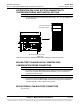
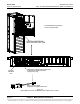
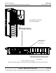
When used with a a Surge Suppression Option
If a bay is equipped with a surge suppression option, an MCA I/O circuit card is furnished.
Connect the remote monitoring leads from each of the two surge suppression assemblies
as follows.
1) Locate the wire harness connected to the surge suppression assemblies.
Connect the leads as follows.
Procedure
a) Connect the BROWN wire (Suppression Assembly A - COMM) to terminal 1
of TB1 located on the MCA I/O circuit card (P/N 524550).
b) Connect the VIOLET wire (Suppression Assembly A - NC) to terminal 2 of
TB1 located on the MCA I/O circuit card (P/N 524550).
c) Connect the YELLOW wire (Suppression Assembly B - COMM) to terminal 3
of TB1 located on the MCA I/O circuit card (P/N 524550).
d) Connect the ORANGE wire (Suppression Assembly B - NC) to terminal 4 of
TB1 located on the MCA I/O circuit card (P/N 524550).
Note: Program the respective binary inputs to alarm in the 'open' state as
outlined in the "INSTALLING THE RECTIFIERS AND INITIALLY
STARTING THE POWER SYSTEM" chapter.
If a surge suppression assembly operates, the MCA displays a "Binary
Input Customer Text Message" in the I/O Board Alarm Detail Message. If
you wish to change the default message, refer to the "SYSTEM
OPERATING PROCEDURES" chapter in Section 5877.
Note that a Surge Suppression Alarm is active when there is NO AC
power, and resets when AC power is supplied.