
Application Guide

Installation Instructions Section 5876
Spec. No. 582140000 (Models 802
NLDB, 802NLEB and 802NL-B) Issue AT, April 26, 2013
Chapter 4. Making Electrical Connections Page 4-19
This document is property of Emerson Network Power, Energy Systems, North America, Inc. and contains confidential and proprietary information owned by Emerson Network Power, Energy
Systems, North America, Inc. Any copying, use, or disclosure of it without the written permission of Emerson Network Power, Energy Systems, North America, Inc. is strictly prohibited.
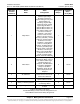
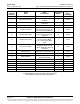
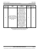
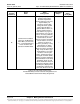
MCA Relay
Function
Channel #
Alarm
Name
Alarm
Configuration
Assigned to
Relay #…
installed in
Slot #…
of any Bay
24
Defines the MCA Alarm
conditions. These conditions
are reported in the Alarm Log
as 'Controller Alarms', and
activate the Primary Bay
Alarm LED.
Emergency Stop Input Active,
Remote High Voltage
Shutdown Input Active,
System Voltage is Very Low,
System Battery On
Discharge, System High
Voltage #1 Alarm, System
High Voltage #2 Alarm, No
PCU in Inventory (installed),
No Dist. Panel in Inventory
(Installed), No Router in
Inventory (installed), No
Relay Board in Inventory
(installed), High Temp #1
Alarm, High Temp #2 Alarm,
Low Temp #1 Alarm, Low
Temp #2 Alarm, Temperature
Sensor No Signal, Controller
(MCA) Failure, Controller
Initializing, Total Distribution
Load Alarm, Distribution
Group A Load Alarm,
Distribution Group B Load
Alarm, Monitoring Does Not
Respond, Display Does Not
Respond, All LMS LED
Channels
6 4
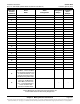
Table 4-1A (cont'd from previous page, cont'd on next page)
Default MCA Relay Function Channel Configurations and
Default MCA Customer Alarm Relay Assignments