
Application Guide


Section 5876 Installation Instructions
Issue AT, April 26, 2013 Spec. No. 582140000 (Models 802
NLDB, 802NLEB and 802NL-B)
Page 2-24 Chapter 2. Placing the Bays and Installing Internal/External Busbars
This document is property of Emerson Network Power, Energy Systems, North America, Inc. and contains confidential and proprietary information owned by Emerson Network Power, Energy
Systems, North America, Inc. Any copying, use, or disclosure of it without the written permission of Emerson Network Power, Energy Systems, North America, Inc. is strictly prohibited.
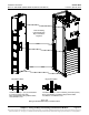
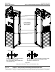
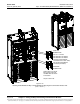
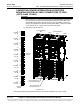
CONNECTING POWER/DISTRIBUTION BAY RECTIFIER
MOUNTING POSITION AC INPUT CONNECTORS TO PDSC
(LISTS 2 AND 12 ONLY)
Procedure
1) Refer to Figure 2-13, and feed the wires from the Rectifier Mounting Position AC
Input Connectors located in a Power/Distribution Bay through the side of the
Rectifier Mounting Position AC Input Cover and into the PDSC. Connect the
wires to the appropriate connectors provided in the PDSC. Observe the labels
on the wires (A, B, C). Torque each connection to 23 in-lbs.
2) Repeat this step for each bay.
Figure 2-13
Connecting Rectifier Mounting Position AC Input Connectors to PDSC (Lists 2 and 12 Only)
Power/Distribution
Bay
Power/Distribution
Bay
PDSC
PDSC
Row of PDSC PCU
AC Input Connectors
Connectors
in PDSC
to
PCU Mtg.
Pos. #1
to
PCU Mtg.
Pos. #2
to
PCU Mtg.
Pos. #3
to
PCU Mtg.
Pos. #4
to
PCU Mtg.
Pos. #5
to
PCU Mtg.
Pos. #6
to
PCU Mtg.
Pos. #7
to
PCU Mtg.
Pos. #8
to
PCU Mtg.
Pos. #9
to
PCU Mtg.
Pos. #10
Torque to
23 in-lbs.
A
B
C
A
B
C
A
B
C
A
B
C
A
B
C
A
B
C
A
B
C
A
B
C
A
B
C
A
B
C
Row of PCU Mtg. Pos.
AC Input Connectors