
Installation Manual

NetSure
™
9500 120kW 400V DC Power System
Installation Manual, IM584001200 (Issue AA, April 14, 2014)
Spec. No: 584001200 Code: IM584001200
Model No: 9500 Issue AA, April 14, 2014
[18 of 25]
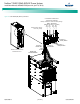
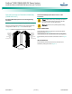
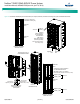
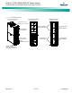
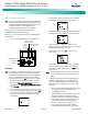
Figure 16. Installing a Rectifier Module into a Power Module/Bay
System Startup
Important Safety Instructions
Caution! Performing various steps in the following
procedures may cause a service interruption and/or
result in the extension of alarms. Notify any appropriate
personnel before starting these procedures. Also, notify
personnel when these procedures are completed.
Note:
Contact Emerson Services for startup assistance.
Initial Preparation
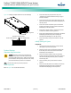
Refer to Figure 17 for circuit breaker locations.
• Ensure that all blocks (except the last one) in the
“Installation Acceptance Checklist” starting on page 1
have been checked.
• Ensure the main AC input circuit breaker located on the
power and control section of the Power Module/Bay is in
the OFF position.
• Ensure each rectifier module AC input circuit breaker
located on the power and control section of the Power
Module/Bay is in the OFF position.
• Ensure that a rectifier module or a blank cover panel is
installed in all rectifier mounting positions.
• Ensure each load distribution circuit breaker in the Power
Module/Bay (if distribution panel is installed) and
Distribution Module/Bay(s) is in the OFF position.
• Ensure each battery string circuit breaker is in the OFF
position.
Initially Starting the System
PROCEDURE
1. Close the external AC disconnect or protective device
that supplies AC power to the system.
2. Place the main AC input circuit breaker located on the
front of the power and control section of the Power
Module/Bay to the ON position.
3. Place each rectifier module AC input circuit breaker
located on the front of the power and control section of
the Power Module/Bay to the ON position. Rectifiers
automatically start.
4. Place each battery string circuit breaker to the ON
position.
5. Place each load distribution circuit breaker in the Power
Module/Bay (if distribution panel is installed) and
Distribution Module/Bay(s) to the ON position.
Power Indicator (Green)
Protection Indicator (Y
ellow)
Alarm Indicator (Red)
Front V
iew
Latch Release
Retaining Screw
C
aut
ion