NetSure™ +24VDC to -48VDC Converter System Installation and User Instructions UM584622100 (Issue AC, July 3, 2012) SPEC. NOS.
Business-Critical Continuity™, Emerson Network Power, and the Emerson Network Power logo are trademarks and service marks of Emerson Electric Co. NetSure™, NetSpan™, NetReach™, NetXtend™, and NetPerform™ are trademarks of Emerson Network Power, Energy Systems, North America, Inc. All other trademarks are the property of their respective owners. The products covered by this instruction manual are manufactured and/or sold by Emerson Network Power, Energy Systems, North America, Inc.
Installation and User Instructions Spec. Nos. 584622100, 584622200, 584622300, 584622400 (Model DCS48375) UM584622100 Issue AC, July 3, 2012 TABLE OF CONTENTS CONTENTS PAGE STATIC WARNING ................................................................................................................... iii ADMONISHMENTS .................................................................................................................. iv General Safety .....................................................
UM584622100 Issue AC, July 3, 2012 Installation and User Instructions Spec. Nos. 584622100, 584622200, 584622300, 584622400 (Model DCS48375) Initially Starting and Checking System Operation .............................................................................................. 26 Initial Startup Preparation ............................................................................................................................ 26 Initially Starting the System ....................................
Installation and User Instructions Spec. Nos. 584622100, 584622200, 584622300, 584622400 (Model DCS48375) UM584622100 Issue AC, July 3, 2012 STATIC WARNING The printed circuit cards used in this equipment contain static sensitive components. The warnings listed below must be observed to prevent damage to these components. Disregarding any of these warnings may result in personal injury or damage to the equipment. 1. Strictly adhere to the procedures provided in this document. 2.
UM584622100 Issue AC, July 3, 2012 Installation and User Instructions Spec. Nos. 584622100, 584622200, 584622300, 584622400 (Model DCS48375) ADMONISHMENTS GENERAL SAFETY Danger: YOU MUST FOLLOW APPROVED SAFETY PROCEDURES. Performing the following procedures may expose you to hazards. These procedures should be performed by qualified technicians familiar with the hazards associated with this type of equipment. These hazards may include shock, energy, and/or burns.
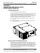
Installation and User Instructions Spec. Nos. 584622100, 584622200, 584622300, 584622400 (Model DCS48375) UM584622100 Issue AC, July 3, 2012 CHAPTER 1. DESCRIPTION AND INSTALLATION ACCEPTANCE CHECKLIST SYSTEM DESCRIPTION +24VDC to -48VDC @ up to 375A Converter System. The NetSure™ DCS48375 Converter System is comprised of a main shelf and up to two (2) expansion shelves. Each shelf provides mounting positions for up to four (4) converter modules.
UM584622100 Issue AC, July 3, 2012 Installation and User Instructions Spec. Nos. 584622100, 584622200, 584622300, 584622400 (Model DCS48375) Note: The system is not powered up until the end of this checklist. Note: Some of these procedures may have been factory performed. Chapter 2.
Installation and User Instructions Spec. Nos. 584622100, 584622200, 584622300, 584622400 (Model DCS48375) UM584622100 Issue AC, July 3, 2012 CHAPTER 2. INSTALLING THE SYSTEM GENERAL REQUIREMENTS The shelf is designed for mounting in a 19-inch or 23-inch wide relay rack with 1-3/4 inch multiple drilling. The installer should be familiar with the installation requirements and techniques to be used in securing the shelf(s) to a relay rack.
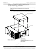
UM584622100 Issue AC, July 3, 2012 Installation and User Instructions Spec. Nos. 584622100, 584622200, 584622300, 584622400 (Model DCS48375) INSTALLING OPTIONAL WIRING ACCESS COVER ON TOP OF SHELF(S), IF DESIRED The optional wiring access cover is a 1U high panel that is installed on top of the shelf(s) to allow greater access to load distribution return connection points. Procedure 1) To install the optional wiring access cover, perform the procedure in Figure 2-1.
Installation and User Instructions Spec. Nos. 584622100, 584622200, 584622300, 584622400 (Model DCS48375) UM584622100 Issue AC, July 3, 2012 MOUNTING THE SHELF(S) The 584622100 and 584622200 shelves are equipped with reversible mounting angles for mounting in a standard 19-inch or 23-inch wide relay rack having 1-3/4 inch multiple drillings. The 584622300 and 584622400 shelves mount in a standard 23-inch wide relay rack having 1-3/4 inch multiple drillings.
UM584622100 Issue AC, July 3, 2012 Installation and User Instructions Spec. Nos. 584622100, 584622200, 584622300, 584622400 (Model DCS48375) Securing the Expansion Shelf(s) to a Relay Rack and Installing the Expansion Wiring Cover on the Main Shelf SECURING AN EXPANSION SHELF TO A RELAY RACK Secure an expansion shelf to a relay rack, directly below the shelf above it, per the previous procedure. The optional 1U wiring access panel is recommended for expansion shelves to facilitate load cable connections.
Installation and User Instructions Spec. Nos. 584622100, 584622200, 584622300, 584622400 (Model DCS48375) UM584622100 Issue AC, July 3, 2012 INSTALLING OPTIONAL LUG ADAPTER BUSBAR KITS Procedure 1) Refer to Figure 2-4 to install the optional lug adapter busbar kits. P/N 545404 P/N 545405 P/N 545571 1. Open the shelf’s front door. 2. Install the lug adapter busbar kits as shown. Apply anti-oxidizing compound to busbar mating surfaces before installing. 3.
UM584622100 Issue AC, July 3, 2012 Installation and User Instructions Spec. Nos. 584622100, 584622200, 584622300, 584622400 (Model DCS48375) INSTALLING BULLET NOSE CIRCUIT BREAKERS AND/OR FUSEHOLDERS (WITH TPS/TPL FUSES) Caution: For ambient temperatures at or below +40°C (+104°F), overcurrent devices rated 100A or greater MUST HAVE an empty mounting position between it and any other overcurrent protective device.
Installation and User Instructions Spec. Nos. 584622100, 584622200, 584622300, 584622400 (Model DCS48375) UM584622100 Issue AC, July 3, 2012 584622100 / 584622200 shown. 584622300 / 584622400 similar. Shorter Side to the Top Shorter Side to the Top Lettering on handle must be right side up. Insert these terminals into corresponding sockets on distribution row. Insert these terminals into corresponding sockets on distribution row. Turn off before installing.
UM584622100 Issue AC, July 3, 2012 Installation and User Instructions Spec. Nos. 584622100, 584622200, 584622300, 584622400 (Model DCS48375) INSTALLING AN OPTIONAL BULLET NOSE GMT FUSE BLOCK Caution: At 40°C ambient, GMT fuses greater than 10A MUST HAVE an empty mounting position between it and any other fuse. Maximum total current is 35A. Maximum GMT fuse size is 15A. At 65°C ambient, GMT fuses greater than 5A MUST HAVE an empty mounting position between it and any other fuse.
Installation and User Instructions Spec. Nos. 584622100, 584622200, 584622300, 584622400 (Model DCS48375) 584622100 / 584622200 shown. 584622300 / 584622400 similar. UM584622100 Issue AC, July 3, 2012 1. Press in tabs to release lug terminal busbars for positions to be occupied by GMT Fuse Block. 2. Remove two lug terminal busbars for positions to be occupied by GMT Fuse Block. Top Cover Removed in Illustration for Clarity Only 3.
UM584622100 Issue AC, July 3, 2012 Installation and User Instructions Spec. Nos. 584622100, 584622200, 584622300, 584622400 (Model DCS48375) CHAPTER 3. SETTING JUMPER AND SWITCH OPTIONS JUMPER AND SWITCH SETTINGS ON THE SYSTEM INTERFACE CIRCUIT CARD Perform the following procedures to verify the factory settings and/or make the required settings per your site requirements. These procedures can also be used to make adjustments on a replacement circuit card.
Installation and User Instructions Spec. Nos. 584622100, 584622200, 584622300, 584622400 (Model DCS48375) UM584622100 Issue AC, July 3, 2012 Jumper P2 Jumper P2 is the CAN termination jumper. a) When in stand alone mode, the jumper P2 must be in place to ensure reliable communications. b) When an ACU+ is on the CAN bus, jumper P2 should be removed.
UM584622100 Issue AC, July 3, 2012 Installation and User Instructions Spec. Nos. 584622100, 584622200, 584622300, 584622400 (Model DCS48375) CHAPTER 4. MAKING ELECTRICAL CONNECTIONS ADMONISHMENTS Observe the admonishments located at the beginning of this document. WIRING CONSIDERATIONS All wiring should follow the current edition of the American National Standards Institute (ANSI) approved National Fire Protection Association's (NFPA) National Electrical Code (NEC), and applicable local codes.
Installation and User Instructions Spec. Nos. 584622100, 584622200, 584622300, 584622400 (Model DCS48375) UM584622100 Issue AC, July 3, 2012 SHELF(S) GROUNDING (FRAME GROUND) CONNECTION For shelf grounding requirements, refer to the current edition of the American National Standards Institute (ANSI) approved National Fire Protection Association's (NFPA) National Electrical Code (NEC), applicable local codes, and your specific site requirements.
UM584622100 Issue AC, July 3, 2012 Installation and User Instructions Spec. Nos. 584622100, 584622200, 584622300, 584622400 (Model DCS48375) EXTERNAL ALARM, REFERENCE, MONITORING, AND CONTROL CONNECTIONS External alarm, reference, monitoring, and control connections are made to terminals of TB1 and TB2 located on the system interface circuit card mounted on the inside of the main shelf’s front door. Refer to Figure 4-2 for location.
Installation and User Instructions Spec. Nos. 584622100, 584622200, 584622300, 584622400 (Model DCS48375) UM584622100 Issue AC, July 3, 2012 Referenced to Minus Battery (input): Provide a jumper between terminals 3 (-BT) and 6 (+IO) of TB2. Not Referenced: Do not provide a jumper. Output Voltage Monitoring An output voltage monitoring device can be connected to terminals 7 (-VO) and 8 (+VO) of TB2. These terminals are internally paralleled with the test points provided on the front door of the main shelf.
UM584622100 Issue AC, July 3, 2012 Installation and User Instructions Spec. Nos. 584622100, 584622200, 584622300, 584622400 (Model DCS48375) LOAD CONNECTIONS To Distribution Bus Row 1/4-20 x 0.625” studs on 5/8” centers are provided for installation of customer provided load distribution leads terminated in 2-hole lugs. Refer to Figure 4-3. Warning: Observe correct polarity when making connections. Otherwise equipment damage may occur.
Installation and User Instructions Spec. Nos. 584622100, 584622200, 584622300, 584622400 (Model DCS48375) Load Distribution Leads Enter Here (break tabs off shield as required) 584622100 / 584622200 shown. 584622300 / 584622400 similar. Components removed in illustration for clarity only. UM584622100 Issue AC, July 3, 2012 Return -48VDC Front Load Distribution Connections * 1/4-20 x 0.625” studs on 5/8” centers for installation of leads with 2-hole lugs. * Maximum lug width 0.625”.
UM584622100 Issue AC, July 3, 2012 Installation and User Instructions Spec. Nos. 584622100, 584622200, 584622300, 584622400 (Model DCS48375) To Optional Bullet Nose 6-Position GMT Fuse Block Warning: Observe correct polarity when making connections. Otherwise equipment damage may occur. Procedure 1) For load connections to an optional GMT fuse block, refer to Figure 4-4. Load Return Leads Load Leads Wire Size Capacity: 26-14 AWG. Recommended Torque: 4.5 in-lbs.
Installation and User Instructions Spec. Nos. 584622100, 584622200, 584622300, 584622400 (Model DCS48375) UM584622100 Issue AC, July 3, 2012 EXPANSION SHELF(S) INTERCONNECTIONS Installing Output Paralleling Leads Procedure 1) Perform the procedure in Figure 4-5 for each expansion shelf. Cable, lugs (P/N 144511), and labels are provided loose with the Expansion Shelf to assemble a Return and a -48V paralleling cable. 1. Cut the cables to the proper length. 2.
UM584622100 Issue AC, July 3, 2012 Installation and User Instructions Spec. Nos. 584622100, 584622200, 584622300, 584622400 (Model DCS48375) FA/CBA and CAN Bus Interconnections Procedure 1) Perform the procedure in Figure 4-6 for each expansion shelf and to connect an external FA/CBA alarm lead to this system. If there are expansion shelves, unplug the external FA/CBA lead from this connector.
Installation and User Instructions Spec. Nos. 584622100, 584622200, 584622300, 584622400 (Model DCS48375) UM584622100 Issue AC, July 3, 2012 DC INPUT CONNECTIONS 3/8-16 x 0.875” studs on 1” centers are provided for installation of customer provided DC input leads terminated in 2-hole lugs. Terminations are provided for each converter module (individual feed). Adapter busbars are provided loose with each shelf which allows two (2) converter modules to be fed by a single input. Refer to Figure 4-7.
UM584622100 Issue AC, July 3, 2012 Installation and User Instructions Spec. Nos. 584622100, 584622200, 584622300, 584622400 (Model DCS48375) 584622100 / 584622200 shown. 584622300 / 584622400 similar. Rear Rear panels removed in illustration. DC Input Leads Enter Here +24VDC Converter #1 (top) Converter #2 Converter #3 Converter #4 (bottom) DC Input Connections * 3/8-16 x 0.875” studs on 1” centers for installation of leads with 2-hole lugs. * Provide separate inputs for each converter.
Installation and User Instructions Spec. Nos. 584622100, 584622200, 584622300, 584622400 (Model DCS48375) UM584622100 Issue AC, July 3, 2012 CHAPTER 5. INSTALLING THE CONVERTER MODULES AND INITIALLY STARTING THE SYSTEM INSTALLING CONVERTER MODULES The converter module is hot swappable. It can be installed with the system operating. Warning: To prevent damage to the latching mechanism, ensure the handle is in the open position when installing or removing a converter module.
UM584622100 Issue AC, July 3, 2012 Installation and User Instructions Spec. Nos. 584622100, 584622200, 584622300, 584622400 (Model DCS48375) INITIALLY STARTING AND CHECKING SYSTEM OPERATION Initial Startup Preparation Ensure that all blocks for Chapters 2 through 4 in the Installation Acceptance Checklist, located in Chapter 1, have been checked. Ensure no objects block the ventilation openings on the system shelf(s).
Installation and User Instructions Spec. Nos. 584622100, 584622200, 584622300, 584622400 (Model DCS48375) UM584622100 Issue AC, July 3, 2012 CHAPTER 6. OPERATING PROCEDURES CONVERTER MODULES Refer to UM1C24481500 (Converter Module User Instructions) for converter module operation instructions. USING THE CONVERTER SYSTEM WITH AN ACU+ CONTROLLER The following outlines the steps to set-up the converter system to be used with an ACU+ controller.
UM584622100 Issue AC, July 3, 2012 Installation and User Instructions Spec. Nos. 584622100, 584622200, 584622300, 584622400 (Model DCS48375) c) Converter Major (Red LED): Illuminates red if more than one converter module fails (or if only one converter module is installed in the system and it fails). Failure conditions are as stated in d) below. d) Converter Minor (Yellow LED): Illuminates yellow if one converter module fails. Failure conditions are as follows.
Installation and User Instructions Spec. Nos. 584622100, 584622200, 584622300, 584622400 (Model DCS48375) UM584622100 Issue AC, July 3, 2012 CHAPTER 7. MAINTENANCE ADMONISHMENTS Observe the admonishments located at the beginning of this document. SYSTEM MAINTENANCE PROCEDURES It is recommended to perform and record the maintenance procedures listed in Table 7-1 every 6-months to ensure continual system operation.
UM584622100 Issue AC, July 3, 2012 Installation and User Instructions Spec. Nos. 584622100, 584622200, 584622300, 584622400 (Model DCS48375) CHAPTER 8. TROUBLESHOOTING AND REPAIR CONTACT INFORMATION Support contact information is provided on the inside of the back cover of this document. ADMONISHMENTS Observe the admonishments located at the beginning of this document.
Installation and User Instructions Spec. Nos. 584622100, 584622200, 584622300, 584622400 (Model DCS48375) UM584622100 Issue AC, July 3, 2012 REPLACEMENT PROCEDURES Replacing a Converter Module Refer to the Converter Module User Instructions (UM1C24481500) for a converter module replacement procedure. Refer also to System Troubleshooting Information in this chapter to clear a converter fail alarm after removing a converter module.
UM584622100 Issue AC, July 3, 2012 Installation and User Instructions Spec. Nos. 584622100, 584622200, 584622300, 584622400 (Model DCS48375) Replacing a TPS/TLS Fuse Note: Refer to Figure 2-5 as this procedure is performed. Procedure 1) Open the shelf’s front door. 2) Remove the fuse carrier from the mounted fuseholder body by pulling it straight out. 3) Remove the open fuse from the fuse carrier and replace it with the same type and rating, or equivalent.
Installation and User Instructions Spec. Nos. 584622100, 584622200, 584622300, 584622400 (Model DCS48375) UM584622100 Issue AC, July 3, 2012 Replacing a Bullet Nose Circuit Breaker or Fuseholder Note: Refer to Figure 2-5 as this procedure is performed. Procedure 1) Open the shelf’s front door. 2) Circuit Breaker: Operate a defective circuit breaker to the OFF position. Fuseholder: Remove the fuse carrier from the mounted fuseholder body by pulling it straight out.
UM584622100 Issue AC, July 3, 2012 Installation and User Instructions Spec. Nos. 584622100, 584622200, 584622300, 584622400 (Model DCS48375) Replacing the System Interface Circuit Card Warning: The system interface circuit card contains static-sensitive devices. Read the Static Warning at the front of this document before performing the following procedure.
Installation and User Instructions Spec. Nos. 584622100, 584622200, 584622300, 584622400 (Model DCS48375) UM584622100 Issue AC, July 3, 2012 12) Reconnect the external wiring to the correct terminals on terminal blocks TB1 and TB2. 13) Plug the connector removed from the old circuit card into the same position on the replacement circuit card. 14) Remove the grounding wrist strap. 15) Enable the external alarms, or notify appropriate personnel that this procedure is finished.
UM584622100 Issue AC, July 3, 2012 Installation and User Instructions Spec. Nos. 584622100, 584622200, 584622300, 584622400 (Model DCS48375) REVISION RECORD Issue Change Number (ECO) AA LLP215922 New AB LLP216279 Optional external FA/CBA plug assembly added. AC LLP217215 Added 584622300 and 584622400. Page 36 Description of Change Revision Record This document is property of Emerson Network Power, Energy Systems, North America, Inc.
NetPerform™ Optimization Services At Emerson Network Power, we understand the importance of reliable equipment – it’s critical to both your business and your bottom line. That is why we offer a wide array of services to meet all of your network infrastructure needs. Technical Support Email DCpower.TAC@Emerson.com OSP.TAC@Emerson.com Phone 1.800.800.5260 Answers technical product and system questions; determines status of warranties and contractual agreements for repair.