AC Power For Business-Critical Continuity™ Liebert NX™ UPS User Manual–10-30kVA, 208V, 60Hz
TABLE OF CONTENTS IMPORTANT SAFETY INSTRUCTIONS . . . . . . . . . . . . . . . . . . . . . . . . . . . . . . . . . . . . . . . . . . . . . . . .1 GLOSSARY OF SYMBOLS . . . . . . . . . . . . . . . . . . . . . . . . . . . . . . . . . . . . . . . . . . . . . . . . . . . . . . . .3 1.0 INSTALLATION . . . . . . . . . . . . . . . . . . . . . . . . . . . . . . . . . . . . . . . . . . . . . . . . . . . . . . . . . .4 1.1 1.2 External Inspections . . . . . . . . . . . . . . . . . . . . . . . . . . . . . . . . . . .
3.4 External Battery Cabinet Installation . . . . . . . . . . . . . . . . . . . . . . . . . . . . . . . . . . . . . . . . . . 20 3.4.1 3.4.2 3.4.3 3.4.4 Matching Battery Cabinets . . . . . . . . . . . . . . . . . . . . . . . . . . . . . . . . . . . . . . . . . . . . . . . . . . . . Connecting the Batteries . . . . . . . . . . . . . . . . . . . . . . . . . . . . . . . . . . . . . . . . . . . . . . . . . . . . . . Installation Considerations . . . . . . . . . . . . . . . . . . . . . . . . . . . . . . . . .
6.0 7.0 INSTALLATION DRAWINGS . . . . . . . . . . . . . . . . . . . . . . . . . . . . . . . . . . . . . . . . . . . . . . . . .44 OPERATION . . . . . . . . . . . . . . . . . . . . . . . . . . . . . . . . . . . . . . . . . . . . . . . . . . . . . . . . . . .58 7.1 7.2 7.3 General Description . . . . . . . . . . . . . . . . . . . . . . . . . . . . . . . . . . . . . . . . . . . . . . . . . . . . . . . . . 58 Bypass Supplies . . . . . . . . . . . . . . . . . . . . . . . . . . . . . . . . . . . . . . . . . .
9.9 Battery Protection . . . . . . . . . . . . . . . . . . . . . . . . . . . . . . . . . . . . . . . . . . . . . . . . . . . . . . . . . . 80 9.9.1 9.9.2 9.9.3 9.10 9.11 9.12 9.13 9.14 9.15 Battery Undervoltage Pre-Warning . . . . . . . . . . . . . . . . . . . . . . . . . . . . . . . . . . . . . . . . . . . . . 80 Battery End-of-Discharge (EOD) Protection. . . . . . . . . . . . . . . . . . . . . . . . . . . . . . . . . . . . . . . 80 Battery Fuse-Blow Warning . . . . . . . . . . . . . . . . . . . . . . .
Figure 13 Figure 14 Figure 15 Figure 16 Figure 17 Figure 18 Figure 19 Figure 20 Figure 21 Figure 22 Figure 23 Figure 24 Figure 25 Figure 26 Figure 27 Figure 28 Figure 29 Figure 30 Figure 31 Figure 32 Figure 33 Figure 34 Figure 35 Figure 36 Figure 37 Figure 38 Figure 39 Figure 40 Figure 41 Figure 42 Figure 43 Figure 44 Figure 45 Figure 46 Figure 47 Figure 48 Figure 49 Figure 50 Figure 51 Figure 52 Figure 53 Figure 54 Figure 55 Figure 56 Figure 57 Figure 58 Figure 59 Figure 60 Figure 61 Narrow battery cabine
TABLES Table 1 Table 2 Table 3 Table 4 Table 5 Table 6 Table 7 Table 8 Table 9 Table 10 Table 11 Table 12 Table 13 Table 14 Table 15 Table 16 Table 17 Table 18 Table 19 Table 20 Table 21 Table 22 Table 23 Table 24 Table 25 Table 26 Table 27 Table 28 Table 29 Table 30 Table 31 Table 32 Table 33 Table 34 Table 35 Table 36 Table 37 Table 38 Table 39 Table 40 Table 41 Table 42 Table 43 Table 44 Input dry contacts at X3 . . . . . . . . . . . . . . . . . . . . . . . . . . . . . . . . . . . . . . . . . . . . . .
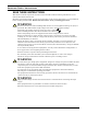
IMPORTANT SAFETY INSTRUCTIONS SAVE THESE INSTRUCTIONS This manual contains important instructions that should be followed during installation of your Liebert NX™ UPS and batteries. Read this manual thoroughly, paying special attention to the sections that apply to your installation, before working with the UPS. Retain this manual for use by installing personnel. ! WARNING Exercise extreme care when handling UPS cabinets to avoid equipment damage or injury to personnel.
! CAUTION ! WARNING ! CAUTION This equipment is fitted with RFI suppression filters. Ground leakage current exceeds 3.5 mA and is less than 1000 mA. Transient and steady-state ground leakage currents, which may occur when starting the equipment, should be taken into account when selecting instantaneous residual current circuit breakers (RCCBs) or residual current devices (RCDs). RCCBs must be selected sensitive to DC unidirectional pulses (Class A) and insensitive to transient current pulses.
GLOSSARY OF SYMBOLS Risk of electrical shock ! Indicates caution followed by important instructions AC input AC output i - Requests the user to consult the manual + Indicates the unit contains a valve-regulated lead acid battery PbH2SO4 R Recycle DC voltage Equipment grounding conductor Bonded to ground AC voltage 3
Installation 1.0 INSTALLATION Liebert’s NX™ Uninterruptible Power Supply system provides continuous, high-quality AC power to your business-critical equipment, such as telecommunications and data processing equipment. The NX UPS supplies power that is free of the disturbances and variations in voltage and frequency common to utility power, which is subject to brownouts, blackouts, surges and sags.
Installation 1.2.1 Storing for Delayed Installation If the equipment will not be installed immediately, it must be stored indoors where the humidity is no higher than 90% and the temperature is no higher than 104°F (40°C). The storage area must protect the NX from excessive moisture (see 10.2 - UPS Environmental). ! CAUTION ! CAUTION If the UPS must remain disconnected from power for more than six (6) months, the battery must be recharged before use.
Installation 1.4.3 Special Considerations for 1+N Systems 1. Consider the grounding configuration of your system before finalizing module placement. For optimal ground performance, the NX modules should be close together. 2. For optimal load-sharing performance, the UPS output cables should be approximately the same length, plus or minus 20 percent. 3. Position modules in such a way as to minimize the length of power cables and control wiring between UPS modules and the paralleling cabinet. 1.
Installation 1.6.1 Clearances There are no ventilation grilles on the sides or rear of the UPS. The sides must be accessible during installation. After installation, the unit may be placed with the rear against a wall and optional cabinets on either side. To enable routine tightening of power terminations within the UPS, make sure there is sufficient clearance in front of the NX to permit free passage of personnel with the door fully opened. Leave a minimum of 2 ft.
Installation 1.6.4 Optional Cabinets If your NX installation includes a Maintenance Bypass Cabinet, the NX must be positioned to allow the Maintenance Bypass Cabinet to be bolted to left side of the NX (see Figure 1). Cables from the Maintenance Bypass Cabinet must be brought through the bottom side of the NX for connection. The Maintenance Bypass Cabinet must be cabled and bolted to the NX before the UPS and bypass cabinet are moved into their final position.
Electrical Connections 2.0 ELECTRICAL CONNECTIONS The UPS requires both power and control cabling once it has been mechanically installed. All control cables must run separate from power cables in metal conduits or metal ducts that are electrically bonded to the metalwork of the cabinets to which they are connected.
Electrical Connections 2.1.2 UPS Input Configuration Figure 2 illustrates the NX in a split bypass (dual-input) configuration. In this configuration the Static Bypass and the Maintenance Bypass lines are supplied from a separate feed from the Main input. Both sources must be protected externally with properly sized protective devices. By default, the unit ships with internal links installed between the Bypass input and Main input (single-input configuration).
Electrical Connections 2.1.4 Cable Connections The rectifier input, bypass and output are easily accessible from the left side of the unit for installation. All require lug type terminations. They are connected to busbars on the left side of the NX and below the switch, as shown in Figure 3. These busbars are accessible when the left side panel is removed. Busbars to connect external batteries are accessible from the front of the UPS.
Electrical Connections 2.1.5 Safety Ground The safety ground busbar is located below the neutral input and output busbars as shown in Figure 5 below. The safety ground cable must be connected to the ground busbar and bonded to each cabinet in the system. All cabinets and cable conduit should be grounded in accordance with local regulations. ! WARNING Failure to follow proper grounding procedures can result in electric shock hazard to personnel or the risk of fire, should a ground fault occur.
Electrical Connections 2.1.7 Cabling Procedure ! CAUTION The operations described in this section must be performed by authorized electricians or qualified technical personnel. If you have any difficulties, contact your local Liebert representative or Liebert Global Services. NOTE Hydraulic pressure pliers, combinative tools and piston ring pliers should be used to connect AC wiring.
Electrical Connections Internal UPS Battery Connections The UPS internal batteries will be connected at the factory, EXCEPT the Anderson connections between the shelves and to the fuses. ! WARNING The DC bus is live when this internal battery connection is made. This connection is to be performed ONLY by Liebert Global Services at startup. Observe the battery cable polarity. Be sure that the battery connector is made with the correct polarity. 11.
Electrical Connections Figure 7 Auxiliary terminal block detail (Monitoring Board) J8 J3 J1 LCD J22 X7 J23 X6 J12 J9 J2 J15 PWR MODEM SNMP CARD X5 J16 J17 Intellislot 2 J13 J21 J25 J28 J4 Intellislot 1 J26 J30 J10 X4 X4 J24 Intellislot 3 BFP INV ACF EPO MBC X2 X1 2.3 Dry in BCB NOTE: The black square ( ) on each slot indicates Pin 1. X3 Dry Contacts The UPS provides input dry contacts and output dry contacts. 2.3.
Electrical Connections 2.3.2 Maintenance Bypass Cabinet Interface J26 and J30 are the MBC interface. Table 2 Maintenance bypass cabinet interface Position Name Description J26.1 T_IT1 Input transformer over temperature (N.C.) J26.2 AUX_I Reserved J26.3 +12V +12V Power J26.4 GND Power Ground J30.1 FUSE Reserved J30.2 F_FAN Fan Fail Alarm (N.C.) J30.3 T_OT 1 J30.4 AUX_O Output Transformer Overtemperature (N.C.
Electrical Connections 2.3.4 Output Dry Contacts There are three output dry contact relays at the X1 slot (see Figure 10 and Table 4). Figure 10 Output dry contacts and EPO wiring for firmware before M170 +12V X2 ACF_O J28 ACF_S ACF_C INV_C BFP_O BFP_S BFP_C Table 4 J25 INV_O J21 J13 INV_S X1 EPO-H EPO-L Output dry contact relays Position Name Description J13.2 BFP_O Bypass feedback protection relay. Normally open. Closed when bypass SCR is shorted. J13.
Electrical Connections Firmware M200 or Later The UPS has an Emergency Power Off (EPO) function operated by a button on the control panel or by a remote contact provided by the user. The EPO button is under a hinged, clear plastic shield. The X2 slot, shown in Figure 11, is the remote EPO input interface. The EPO has a NO/NC contact point becomes active when shorting terminals X2: 3 and 4 or open terminal connection X2: 2 and 1.
Battery Installation 3.0 BATTERY INSTALLATION 3.1 Introduction Liebert recommends that the batteries in external cabinets match the internal batteries in the NX in manufacturer and type. If using multiple sets of batteries connected in parallel to provide the required battery backup run times, fit each set with an isolating device to permit working on one of the battery sets while leaving the others in service and providing backup protection.
Battery Installation 3.4 External Battery Cabinet Installation 3.4.1 Matching Battery Cabinets Two sizes of optional battery cabinets are available. Refer to Figures 13 and 14. The same model battery cabinet may be installed in parallel in multiple cabinet strings for additional capacity. Battery run time depends on the cabinet model, the number of cabinets and the load on the UPS. Handling—The battery cabinet has casters to facilitate movement over short distances.
Battery Installation Figure 13 Narrow battery cabinet, 27 in. (690mm) - rear view Top cable entry BCB plate and BCB Battery trays Figure 14 Wide battery cabinet, 57 in.
Battery Installation 3.4.3 Installation Considerations Position—Liebert battery cabinets come in versions specific to either the left or right side of the UPS. Control wires and power cables are cut to different lengths for the different versions. If the system includes a matching maintenance bypass cabinet (MBC), the MBC should be mounted to the left of the UPS (nearest the busbars) and the battery cabinet(s) should be installed to the right of the UPS.
Battery Installation Figure 15 Internal cable wiring from battery cabinet to Liebert NX Power cables from output power switch Power cables from batteries Power cables exit battery cabinet, enter Liebert NX Power cables run across top of Liebert NX BATTERY CABINET RIGHT SIDE INTERIOR OF UPS Power cables (black) enter channel down side of NX to power input connections RIGHT SIDE CABLE ENTRY SHOWN; CUTOUTS ON LEFT SIDE PERMIT CONNECTION FROM THAT SIDE.
Battery Installation 3.4.4 Connecting the Battery Cabinet to the UPS After the battery cabinet equipment has been positioned and secured for operation and the batteries have been connected, connect the power cables as described below. (See Figure 36.) 1. Verify that all incoming high and low voltage power circuits are de-energized and locked out or tagged out before installing cables or making any electrical connections. 2. Remove the UPS left side panel to gain access to the equipment ground busbar. 3.
Maintenance Bypass Cabinet 4.0 MAINTENANCE BYPASS CABINET The Maintenance Bypass Cabinet is designed to operate in UPS mode, bypass mode and maintenance mode. The mode is selected using the Bypass Switch. Figure 17 Single UPS with external Maintenance Bypass Cabinet—typical configuration 4.1 Bypass Switch The Bypass Switch allows easy and rapid transfer of connected loads between the UPS and Bypass source. 4.
Maintenance Bypass Cabinet 4.3 Bypass Mode When the Maintenance Bypass Cabinet is in the Bypass mode, it provides an alternate path for power to the connected equipment. Should the UPS need to be taken out of service for limited maintenance or repair, manual activation of the bypass will cause an immediate transfer of the equipment from the UPS inverter to the bypass source. In this mode, power will still be supplied to the UPS; however, the load is NOT protected by the UPS. 4.
Maintenance Bypass Cabinet 4.6.2 Power Cable Installation Refer to Tables 35, 36 and 38 when selecting cables. NOTE Transient and steady state earth leakage currents may occur when starting the equipment. This should be taken into account when selecting ground current detection devices because these will carry the earth leakage currents of both the UPS equipment and the load. 4.6.
Maintenance Bypass Cabinet 7. Connect the system input cables between the Maintenance Bypass Cabinet 'UPS Input' Busbars (A-B-C N terminals) and UPS input busbars (A-B-C N terminals) and tighten the connections to 44 lb-in. (5 N-m) (M6 bolt). 8. Connect the system outnput cables between the Maintenance Bypass Cabinet 'UPS Output' Busbars (A-B-C N terminals) and UPS output busbars (A-B-C N terminals) and tighten the connections to 44 lb-in. (5 N-m) (M6 bolt). 9.
Maintenance Bypass Cabinet 4.7 Bolting Cabinets Together NOTE UPS wiring must be completed before the cabinets are bolted together. 1. Line up cabinets so that mounting holes are aligned. Place cabinets so mounting holes are aligned. A bolt from the adjacent cabinet may be screwed into the threaded top hole, or a bolt may be inserted through the lower hole and screwed into the threaded hole in the adjacent cabinet. 2. Using supplied hardware, bolt the cabinets together.
Option Installations 5.0 OPTION INSTALLATIONS 5.1 Load Bus Synchronization The Load Bus Synchronizer (LBS) keeps the output of two independent UPS systems or parallel UPS systems in synchronization even when the systems are operating in different modes and even when either or both systems are operating on batteries. When the LBS is used, one UPS system is designated as master, the other as slave.
Option Installations 5.2 Configuring Parallel System Operation 5.2.1 General The NX uses intelligent and reliable decentralized technology to achieve parallel operation of two or more modules of the same rating. The 1+N system is used to: • Increase the reliability of the system to ensure adequate power supply to the critical load connected.
Option Installations 5.2.2 Features of Parallel System • The hardware and firmware for parallel UPS module operation is standard in the NX, and the configuration can be set up by changing the settings in configuration software. • It is easy to install the parallel cables in a ring, providing high reliability and redundancy. And the intelligent paralleling logic provides the user with maximum flexibility.
Option Installations 5.2.3 Operating Principles Redundancy Paralleling The 1+N parallel redundant system can noticeably improve system reliability. In normal condition, none of the UPS modules work at full load. That means that even if the load is increased, the system will not transfer to bypass. And when a UPS module shuts down due to any failure, the remaining UPS modules can still power and protect the load.
Option Installations 5.3.5 Power Cables Wiring of power cables is similar to that of single-module system (See 2.1 - Power Cabling). The bypass sources of all modules should be the same, and the outputs should be connected altogether correctly. Power cables will be supplied by customer. Power cables to the UPS’s of the 1+N paralleling cabinet must be routed through either the top or bottom entry access of the UPS.
Option Installations :X T M IAN T X2 2 P2 X2 1 P1 DBS X3 485485+ Figure 24 Auxiliary dry contact cables for output breaker in multi-module system ! CAUTION The auxiliary control wire must be installed to ensure proper operation of the system. NOTE For startup procedure, see the UPS operations and maintenance manual, SL-25210. Figure 25 Dry contacts, multiple UPS modules with distribution panel Input Distribution UPS 1 UPS 2 UPS N M3 Board X3 Ext. Maint. Ext. Out M3 Board X3 Ext. Maint.
Option Installations 5.3.7 Emergency Power Off (EPO) The external emergency stop facility is identical to that described for the single-unit installation— that an individual emergency stop button is provided for each unit. Figure 26 Connecting EPO push button UPS2 X2:3 X2:4 X2:3 X2:4 Monitor Board Monitor Board UPS1 Normally Open EPO UPS2 X2:1 X2:2 X2:1 X2:2 Monitor Board Monitor Board UPS1 Normally Closed EPO 5.
Option Installations Figure 27 Battery circuit breaker box connections 3.9" (98mm) 10.8" (274mm) 5.4" Connect to UPS Module (field-installed) (3) 1/2" (12.7mm) dia. knockouts for control wiring conduit entry 2.5" (63.5mm) 4.0" (101.2mm) J10.2 J10.3 (-) Midpoint (+) (GND) (137mm) 8.3" (211.7mm) Top View 1 2 3 4 5 6 20.0" (508mm) 15.0" (381mm) Midpoint TB1 (-) CB Load Side (+) COM Black TB1 N.O. Red Circuit Breaker N.C.
Option Installations 5.5 Battery Start With this option, the NX UPS can be started with power supplied only by the batteries (at charged condition). This type of start, in the absence of utility power, allows independent utilization of battery power and provides for higher availability in some circumstances. ! 5.6 CAUTION Before attempting to start the UPS without utility power present, ensure that the batteries are fully charged—over 2.1V per cell—and will supply adequate run time to the load.
Option Installations 5.10 OC Web Card—SNMP/HTTP Network Interface Card This network interface card provides all real-time data and status information as SNMPv1 traps for connection to a 10/100-baseT Ethernet connection. The same card also will transmit the same status information and all measured parameters for display via a Web browser.
Option Installations 5.10.1 Configuring Baud Rates The default baud rate for Intellislots is 9600. To communicate with the OCWEB-LB, Modbus/Jbus, or the MultiLink cards, the baud rate must be set to 2400. To change the baud rate (refer to Table 8): 1. Use the Navigation keys directly below the LCD to highlight the Settings Screen. 2. Press F1 to move the highlight into the Data & Settings area of the LCD. 3.
Option Installations Figure 28 OC Web card display 41
Option Installations 5.11 Relay Card The relay card provides voltage-free contact closures for remote monitoring of alarm conditions. Delivering On Battery, On Bypass, Low Battery, Summary Alarm, UPS Fault and On UPS signals, the easy-to-install card integrates with AS/400 computers (additional cable required) and other relay contact monitoring systems. The relay card is rated for 24 VAC/DC at 1A. and supported in any of the three Intellislot bays on the NX.
Option Installations 5.12 MultiPort 4 Card The MultiPort 4 card provides four sets of voltage-free contact closures for remote monitoring of alarm conditions UPS operation On Battery and battery low condition. A typical applicaton is to allow a maximum of four computer systems to simultaneously monitor the status (e.g., utility power failure-low battery) of a singleUPS. This card is supported in any of the three Intellislot bays on the NX.
Installation Drawings 6.0 INSTALLATION DRAWINGS The diagrams in this section illustrate the key mechanical and electrical characteristics of the NX UPS System cabinets. Figure 30 Dimensional view- front and left side views 600 825 10mm dia. threaded mounting holes Monitoring Panel Leveler 1600 Detail “A” Rear of unit shown without side panel Air intake area. Do not block air filter. 90 FRONT VIEW LEFT SIDE VIEW Adjustable Stops (see Note 11) 1. All dimensions are in millimeters. 2.
Installation Drawings Figure 31 Dimensions continued—top and bottom views 10mm dia. threaded mounting holes 4 (typ). See Notes 8 and 9 above.
Installation Drawings Figure 33 Cable connections AC output cable connections Bypass AC input cable connections Input Neutral Bus (side view) Input/Output Neutral Output Neutral Bus (side view) Earth Power Earth (side view) Battery connections (+ N -) 4.1 to battery 4.2 to external battery cabinet NOTES 1. All dimensions are millimeters. 2. Top and bottom cable entry available through removable access plates. Remove, punch to accommodate conduit size and replace. 3.
Installation Drawings Figure 34 Location of internal batteries Battery 186mm 417mm 687mm 47
Installation Drawings Figure 35 Battery connections DYNASTY BATTERY TOP LAYER MIDDLE LAYER W506 to W507 W501 3pcs + - + - + - + - - + - + - - + - + - + - + - + - + - + - + + - + W500 18pcs W510 to W511 W502 to W503 W503 to W502 W504 to W505 BOTTOM LAYER W511 to W510 W507 to W506 W509 to W508 + N - + - + - + - + - + - + - + - + - CON4 W505 to W504 48 W508 to W509
Installation Drawings Negative (-) Positive (+) Refer to Table 11 for key to interconnection Midpoint (N) Figure 36 Battery cabinet interconnection Positive (+) Midpoint (N) Negative (-) Breaker Detail Connection Detail Breaker Detail A A B B B OR A UPS Module Front View with doors removed 27" Battery Cabinet Front View without doors and protective plates 59" Battery Cabinet Front View without doors and protective plates NOTES: 1.
Installation Drawings Figure 37 Maintenance Bypass interconnection Refer to Table 12 for key to interconnection Maintenance Bypass/Transformer Cabinet front view without front door and panel UPS Module left-side view without side panel NOTES 1. All Liebert-supplied cable must be repositioned prior to and while the cabinets are being placed in their final installed location. 2. All interconnection hardware supplied by Liebert. 3.
Installation Drawings Figure 38 NX 1+1 parallel cabinet interconnections 1+1 Parallel Cabinet (Front View Without Front Door and Panel) J J J A D1 D2 E1,E2 F1,F2 C H F1, F2 K1,K2 D1 D2 H B B F1,F2 G I G H K1 K2 I D1,D2 A D1 D2 G F1,F2 I E1,E2 I UPS Module Left Side View (Without Side Panel) Type A00 Type BR0 Type DR1 & CR1 NOTES: 1. All Liebert-supplied cable will need to be repositioned prior to and while setting the cabinets in their installed location. 2.
Installation Drawings Figure 39 Lineup detail—SlimLine distribution cabinet to NX E H A C H G B D D G E H NOTES: 1. All Liebert-supplied cable will need to be repositioned prior to and while setting the cabinets in their installed location. 2. All interconnection cables and hardware supplied by Liebert. 3. AC connections must be made to the UPS module before attaching. 4. See Figure 43 for placement of distribution cabinet. 5.
Installation Drawings Figure 40 Lineup detail—1+N Type A connection to NX 1 + N Parallel Cabinet (front view without front door and panel) 1. All Liebert-supplied cable must be repositioned prior to and while setting the cabinets in their installed location. 2. All interconnection cables and hardware supplied by others. 3. AC connections must be made to the UPS modules before attaching paralleling cabinet to UPS modules 4.
Installation Drawings Figure 41 Lineup detail—1+N Type B1 connection to NX 1 + N Cabinet Side View (without side panel or door) UPS Module Left Side View (without side panel) Table 16 1 + N Parallel Cabinet (front view without front door and panel) 1 + N Cabinet Interior View (neutral and ground busbar location) 1. All Liebert-supplied cable must be repositioned prior to and while setting the cabinets in their installed location. 2. All interconnection cables and hardware supplied by others. 3.
Installation Drawings Figure 42 Lineup detail—1+N Type C connection to NX 1 + N Cabinet Side View (without side panel or door) 1 + N Parallel Cabinet (front view without front door and panel) 1. All Liebert-supplied cable must be repositioned prior to and while setting the cabinets in their installed location. 2. All interconnection cables and hardware supplied by others. 3. AC connections must be made to the UPS modules before attaching paralleling cabinet to UPS modules. 4.
Installation Drawings Maintenance Bypass / Transformer Cabinet Liebert NX UPS Front of Units Battery Cabinet Battery Cabinet Front of Units Slimline Distribution Slimline Distribution Front of Units Maintenance Bypass / Transformer Cabinet Battery Cabinet Liebert NX UPS Front of Units Liebert NX UPS Maintenance Bypass / Transformer Cabinet Front of Units Liebert NX UPS Front of Units Battery Cabinet Liebert NX UPS Front of Units 56 Liebert NX UPS Front of Units Liebert NX UPS Batte
Installation Drawings Figure 44 Suggested placement, multiple NX units with auxiliary cabinets Liebert NX UPS Liebert NX UPS Liebert NX UPS Multi-Module Paralleling Cabinet Front of Units Battery Cabinet Liebert NX UPS Battery Cabinet Liebert NX UPS Battery Cabinet Front of Units 57 Liebert NX UPS Multi-Module Paralleling Cabinet
Operation 7.0 OPERATION 7.1 General Description The standard NX consists of the UPS and internal batteries in a compact, single cabinet. As shown in Figure 45, the AC utility source is input at CB1 and the rectifier converts the AC utility into DC power. The inverter converts that DC power from the utility—or DC power from the batteries—into AC power for the load. The batteries power the load through the inverter in the event of a power failure.
Operation Normal Mode Operating in normal mode, the NX’s rectifier derives power from a utility AC source and supplies regulated DC power to the inverter, which regenerates precise AC power to supply the connected equipment. The rectifier also uses the utility source power to charge the batteries. Battery Mode When utility AC power fails, the NX protects the critical load by instantaneously channeling battery power to the inverter which continues supporting the critical load without interruption.
Operator Control and Display Panel 8.0 OPERATOR CONTROL AND DISPLAY PANEL 8.1 Operator Control Panel The control panel and LCD on the front of the Liebert NX lets the operator: • • • • turn the UPS on or off transfer into the various operating modes silence alarms check the status of the UPS and its batteries, including all measured parameters, events and alarms The main areas of the control panel are shown below in Figure 46 and detailed in Figure 47.
Operator Control and Display Panel 8.2 Mimic Display Indicators The Mimic display on the front panel consists of six indicators arranged in a single-line diagram depicting the various paths of UPS power, as shown in Figure 48. Figure 48 Mimic display indicators location Mimic indicators 1. Rectifier indicator 2. Battery indicator 3. Bypass indicator 4. Inverter indicator 5. Load indicator 6. Status indicator 2 1 3 4 5 6 2006-01-22 Unit #1 Liebert NX 30KVA-3X3 Main Bypass 120 20.5 50.1 208 0.99 P.
Operator Control and Display Panel 8.3 Control Buttons The Control Buttons on the front panel may be used to shut down the UPS completely, turn the inverter on or off, restart the UPS after a fault and silence the alarm, as shown in Figure 49. The function of each button is described in Table 19. NOTE To activate a button properly, press and hold until you hear a short beep—about two seconds.
Operator Control and Display Panel 8.5 LCD Overview The LCD on the front panel has five main sections, as shown in Figure 51. Press the F1 key below the LCD to scroll through these sections. • UPS system information - view UPS name and model, date and time, overall status (see Table 21). • LCD Menu - choose a category of data items to appear below the menus (see Table 22). • Data and settings - view data items for the selected menu (see Table 22).
Operator Control and Display Panel 8.6 Navigation Keys The navigation keys on the front panel—F1 through F4 and Help—are used to access the LCD to view the current status and other information about the NX. Navigation key icons on the LCD appear above each key to indicate its operation (see Table 20). The keys are “soft keys” that can change functions according to the icon. • Use F1 either to move to a different portion of the LCD (shift icon) or to escape to a previous view (ESC icon).
Operator Control and Display Panel 8.8 LCD Menus and Data Items The LCD menus provide access to the following categories of information and settings for the UPS. Selecting a menu changes the information displayed in the UPS data items portion of the LCD. The menu choices are listed below and described in detail in Table 22.
Operator Control and Display Panel 8.9 Language Selection The LCD menus and data display are available in 12 languages (Chinese, Dutch, English, French, German, Italian, Japanese, Polish, Portuguese, Russian, Spanish and Swedish).
Operator Control and Display Panel Table 22 Descriptions of UPS menus and data window items Menu Type Mains (input) TX Input Bypass Output TX Output Load System Item Type Explanation L-N voltage (V) Phase voltage L-N current (A) Phase current Frequency (Hz) Input frequency L-L voltage (v Line-line voltage Power factor Power factor L-N voltage (V) Phase voltage L-L voltage (V) Line-line voltage L-N voltage (V) Phase voltage Frequency (Hz) Bypass frequency L-L voltage (A) Line-
Operator Control and Display Panel Table 22 Descriptions of UPS menus and data window items (continued) Menu Type Item Type Display contrast Settings Command (start / stop battery & system tests) Explanation Adjust the LCD display contrast Date format set Choose the format for date display: M/D/Y, D/M/Y, M/D/Y, Y/M/D Date & time Set the date and time Comm1 baud rate Communication baud rate setting for Intellislot 1 Comm2 baud rate Communication baud rate setting for Intellislot 2 Comm3 baud
Operator Control and Display Panel 8.11 UPS Status Messages The NX displays status changes as they occur in the current status window of the LCD, then stores that data in the history log, as shown in Figure 53. • Current Status Window: The status messages are displayed chronologically and include the date and time of the events. Three status messages are visible in the window at a time. To see other messages, use the navigation keys to scroll up or down the list.
Operator Control and Display Panel 8.12 Types of LCD Screens This section provides a quick guide to the main types of LCD screens. 8.12.1 Opening Display As the UPS begins powering up, the opening display appears, as shown in Figure 54. Figure 54 Opening display F1 F2 F3 HELP F4 8.12.2 Default Screen After the UPS has powered up and completed a self-test, the output screen appears, as shown in Figure 55. This window is the default screen.
Operator Control and Display Panel 8.12.3 UPS Help Screen Press the HELP key below the LCD to display the Help window shown in Figure 56. (Press the HELP key again to exit the Help window.) Figure 56 Help screen Help information Select the current record window Select the previous menu item Q3 Q2 Q5 Q1 Press help key back to main menu F1 F2 F3 F4 HELP 8.12.4 Screen Saver Window If there has been no interaction with the NX’s LCD for 2 minutes, the screen saver window appears.
Operator Control and Display Panel 8.13 Pop-Up Windows Pop-up prompt windows appear when the user must confirm a choice or perform an operation. This section describes the pop-up windows. 8.13.
Operating Instructions 9.0 OPERATING INSTRUCTIONS 9.1 NX Operating Modes The NX can operate in any of four modes, as shown in Table 23. This section provides instructions on switching between modes, resetting the UPS, switching the inverter On and Off and performing other operations. Table 23 UPS operating modes Operating Mode Rotary Switch Position Normal Operation NORMAL The UPS is powering the load.
Operating Instructions 9.1.1 Power Switches The UPS can be isolated by means of power switches, mounted inside the cabinet and accessible after opening the front door. The location of the UPS power switches is shown in Figure 58. Figure 58 Power switches - 10kVA NX CB1 - Utility Connection Inside the door, left side SW1 - Rotary Switch Inside the door, near the center (above the batteries) The UPS unit power switches are CB1 and SW1. • CB1 - Input Isolator. Connects the utility supply to the UPS input.
Operating Instructions 9.2 UPS Start Up The NX must be fully installed and commissioned before start up, and external power isolators must be closed. Once those general conditions are met, the UPS may be started. 9.2.1 Start-Up Procedure To start the UPS from a fully powered-down condition: 1. Open the UPS door to gain access to the main power switches. ! WARNING During this procedure the output terminals will become live.
Operating Instructions 5. Turn the rotary switch to NORMAL, then press the INVERTER ON control button for 2 seconds. The inverter will start and the inverter indicator will flash green. After the inverter is ready, the UPS transfers from bypass to inverter, the bypass indicator turns off and the inverter and load indicators turn on. The UPS is operating normally. The UPS Mimic display indicators will: 9.2.
Operating Instructions 9.3 Switching the UPS from Normal to Maintenance Bypass Follow the procedure below to transfer the load from the inverter output to the Maintenance Bypass line of the UPS. ! CAUTION Before performing this operation, read the messages on the LCD to be sure that bypass supply is regular and the inverter is synchronous with it. If those conditions are not present, there is a risk of a short interruption in powering the load. This procedure assumes that UPS is operating normally. 1.
Operating Instructions 9.5 Powering Down the UPS and Maintaining Power to Load NOTE An external Maintenance Bypass Cabinet must be installed before attempting to perform the following procedure. If the UPS needs to be shut down completely while maintaining power to the load, follow these steps: 1. Perform Steps 1 through 5 in 9.3 - Switching the UPS from Normal to Maintenance Bypass. 2. Close the external maintenance bypass rotary switch to Maint postion.
Operating Instructions 9.6 Emergency Shutdown With EPO This circuit has been designed to switch off the UPS in emergency conditions (i.e., fire, flood, etc.). The system will turn off the rectifier, inverter and stop powering the load immediately (including the inverter and bypass), and the battery stops charging or discharging. If the input utility is present, the UPS’s controls will remain active; however, the output will be turned off.
Operating Instructions 9.9 Battery Protection 9.9.1 Battery Undervoltage Pre-Warning Before the end of discharge, the NX displays a battery undervoltage pre-warning. After this pre-warning, the battery has the capacity for 5 minutes discharging with full load (default time). The NX can be user-configured to display this warning from 3 to 60 minutes before end-of-discharge. 9.9.
Operating Instructions 9.11 Inserting One Module into a Multi-Module System This procedure outlines how to integrate a UPS module that has been previously isolated from other modules of a group of paralleled UPS modules. It is assumed that the installation is complete, the system has been commissioned by authorized personnel and the external power isolators are closed. WARNING ! Mains voltage will be applied to UPS output terminals.
Operating Instructions 9.12 Shutting Down a Multi-Module System Without System Bypass Switch NOTE Before beginning this procedure, shut down the connected load to prevent the possibility of damage. This procedure will shut off power to the load. 1. Open the UPS door to gain access to the main power switches, SW1 and CB1of a UPS in the system. 2. Turn the rotary switch to BYPASS position. Rotating any UPS Rotary Switch (SW1) to the Bypass position will force all UPS modules to Static Bypass 3.
Operating Instructions 9.14 Commissioning a Parallel System ! CAUTION The operations described in this section must be performed by authorized electricians or qualified technical personnel. If you have any difficult, do not hesitate to contact Liebert Global Service at 1-800-LIEBERT. Check the input and output wiring of each UPS module. Ensure that the phase rotation sequence of the main inputs and the bypass inputs and outputs of each UPS module are the same.
Operating Instructions The procedure can be performed only after the installation has been completed (which includes the maintenance bypass cabinet), after the system has been placed in operation by authorized personnel and after the external power switches have been closed. See Figure 60 for more information.
Operating Instructions 9.16 Parallel System Start Up 1. Start each UPS normally as described in 9.2 - UPS Start Up 2. Turn on the inverter of each UPS module one at a time. 3. Apply the load after the last UPS module transfers to inverter. The total load can be determined through the LCD of either UPS. 4. Verify the load rate of each UPS module. If the load rates are roughly the same, then the parallel system may be assumed to be operating normally.
UPS Specifications 10.0 UPS SPECIFICATIONS These specifications describe requirements for the Liebert NX UPS. 10.1 Conformity and Standards The UPS has been designed to conform to the following standards: • • • • • • • • • IEEC1000-4-5 ASME CSA 22.2, No. 107.1 FCC Part 15, Class A ISO 9001 National Electrical Code (NFPA-70) NEMA PE-1 OSHA UL Standard 1778 The UPS system has UL and c-UL approval. 10.
UPS Specifications 10.
UPS Specifications 10.4.1 Battery Manufacturers and Models Either of two manufacturers’ batteries will be installed in the NX 10-30 kVA 208V as shipped. Below are the battery makers and the models they supply. Table 28 Approved batteries Battery Manufacturer Models Supplied Enersys Yuasa C&D Dynasty NPX-80FR NPX-100FR NPX-150FR UPS12-100MR UPS12-140MR - 10.4.
UPS Specifications 10.4.4 Inverter Output Table 31 Inverter output Rated Power 10kVA 15kVA Rated voltage, VAC 20kVA 30kVA 120/208 Supply 3-phase, 4-wire plus ground Frequency, Hz Rated Power, kW 50 / 60 8 12 16 24 10 minutes - 105-125% load Three -phase transient overload, min. load 1 minute - 126-150% load Voltage Regulation % ±1.0% three-phase RMS average for a balanced three-phase load ±2.
Specifications and Technical Data 11.0 SPECIFICATIONS AND TECHNICAL DATA 11.1 Lug Size and Torque Requirements Use commercially available solderless lugs for the wire size required for your application. Refer to Table 33. Connect wire to the lug using tools and procedures specified by the lug manufacturer. Table 33 Torque specifications Nut and Bolt CombinationS Grade 2 Standard Electrical Connections with Belleville Washers Bolt Shaft Size Lb-in N-m Lb-in N-m 1/4 5/16 3/8 1/2 53 107 192 428 6.
Specifications and Technical Data Table 35 kVA Type Maintenance bypass cabinet electrical data (single input) Maintenance Bypass I/P Voltage (VAC) Bypass Cabinet Max Input Current Cabinet Input OCP CB Size (A) O/P Voltage (VAC) Nominal O/P Current Rating (A) Output OCP CB Size (A) 30 A, J 208 104 125 208 83 125 30 B, K 480 47 60 208 83 125 30 B, K 600 37 50 208 83 125 30 B, K 220 101 125 208 83 125 30 C, L 480 48 60 480 36 50 30 C, L 600 38 50 600 29 4
Specifications and Technical Data Table 35 kVA Type Maintenance bypass cabinet electrical data (single input) (continued) Maintenance Bypass I/P Voltage (VAC) Bypass Cabinet Max Input Current Cabinet Input OCP CB Size (A) O/P Voltage (VAC) Nominal O/P Current Rating (A) Output OCP CB Size (A) 10 A, J 208 35 50 208 28 40 10 B, K 480 16 20 208 28 40 10 B, K 600 12 15 208 28 40 10 B, K 220 34 50 208 28 40 10 C, L 480 16 20 480 12 15 10 C, L 600 13 20 600 1
Specifications and Technical Data Table 37 System Size Multi-module bypass cabinet electrical data Type A00, BR0 1+1 kVA System I/P Voltage (VAC) System Max Input Current System Input OCP CB Size (A) O/P Voltage (VAC) Nominal O/P Current Rating (A) Output OCP CB Size (A) 30 208 104 125 208 83 125 20 208 70 90 208 56 70 15 208 53 70 208 42 60 10 208 35 45 208 28 40 CR1 30 208 107 150A 208 83 125 CR1, DR1 30 220 101 150A 208 83 125 CR1, DR1 30 480 46
Specifications and Technical Data Table 38 Maintenance bypass cabinet lug sizes Input Maximum Recommended Lug Unit Rating Nominal System Input Voltage Bolt Size Lug T&B One Hole 54000 Lug T&B One Hole REDDY 30 600 6M (1/4") 54105 62204 30 480 6M (1/4") 54106 62204 30 240 6M (1/4") 54152 62205 30 220 6M (1/4") 54152 62205 30 208 6M (1/4") 54152 62205 20 600 6M (1/4") NA 62204 20 480 6M (1/4") 54130 62204 20 240 6M (1/4") 54107 62204 20 220 6M (1/4") 54107 6
Specifications and Technical Data Table 39 Battery cabinet physical characteristics Battery Cabinet Type Dimensions WxDxH in. (mm) Net Weight Without Batteries, lb. (kg) Short Narrow 27.2x31.4x63 (690x825x1600) 551 (250) Short Wide 58.5x31.4x63 (1488x825x1600) 889 (400) Table 40 Maintenance Bypass Cabinet weights Maintenance Bypass Cabinet Style, lb.
Specifications and Technical Data 11.2 Cable Lengths: Floor to Connection Point Inside UPS To help calculate the total cable length required, refer to Table 43 for the distance from the floor to selected connection points inside the NX. Determine the cable length required to reach the NX, then add the appropriate length from the table and adequate slack for repair and maintenance. Table 43 Distance to connection points on the NX UPS Distance From Floor in. (mm) From Top of Unit in.
UPS Status Messages APPENDIX A - UPS STATUS MESSAGES Table 44 shows all event messages as they appear in the current status area of the LCD or the history log, along with a description and recommended actions, if any. For further information on the current status area and the history log, see 2.11 - UPS Status Messages. Table 44 UPS status messages Event Message Description / Suggested Action (if any) Inverter Comm. Fail The RS485 communication between internal monitor and inverter fails.
UPS Status Messages Table 44 UPS status messages (continued) Event Message Description / Suggested Action (if any) Bypass Unable to Trace This alarm is triggered by an inverter software routine when the amplitude or frequency of bypass voltage is beyond the normal range. The amplitude threshold is fixed for positive and negative 10% rating. This alarm automatically resets once the bypass voltage goes normal. 1.
UPS Status Messages Table 44 UPS status messages (continued) Event Message Description / Suggested Action (if any) Inverter Contactor Fail The Inverter contactor has failed. This alarm is triggered when the feedback signal and the state of the contactor is not identical for a specified time. Contact Liebert Global Services at 800-543-2378 for assistance. Output Fuse Fail At least one of the output fuses is open. Contact Liebert Global Services at 800-543-2378 for assistance.
UPS Status Messages Table 44 UPS status messages (continued) Event Message Description / Suggested Action (if any) DC Bus Overvoltage Rectifier, inverter and battery converter were shutdown because DC bus voltage is too high. Check whether there is a fault in rectifier side. If no, then check whether overload occurs. Restart the inverter after resetting the fault. If fault does not clear, contact Liebert Global Services at 800-543-2378 for assistance.
UPS Status Messages Table 44 UPS status messages (continued) Event Message Description / Suggested Action (if any) Battery Contactor Open Battery Contactor Open Battery Contactor Close Battery Contactor Close Battery Reverse Connect the battery again and check the wiring of batteries No Battery Check the battery and the wiring of batteries Auto start After UPS was shutdown at EOD, inverter auto starts when utility restore. BCB closed BCB closed from dry contact signal.
UPS Status Messages 102
Ensuring The High Availability 0f Mission-Critical Data And Applications. Emerson Network Power, the global leader in enabling business-critical continuity, ensures network resiliency and adaptability through a family of technologies—including Liebert power and cooling technologies—that protect and support business-critical systems. Liebert solutions employ an adaptive architecture that responds to changes in criticality, density and capacity.