
User manual


Electrical Connections
10
2.1.2 UPS Input Configuration
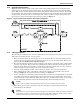
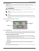
Figure 2 illustrates the NX in a split bypass (dual-input) configuration. In this configuration the
Static Bypass and the Maintenance Bypass lines are supplied from a separate feed from the Main
input. Both sources must be protected externally with properly sized protective devices. By default,
the unit ships with internal links installed between the Bypass input and Main input (single-input
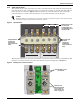
configuration). To wire the unit as a dual input UPS, remove the links and wire the bypass to the
input bus bars, then wire the Main input directly to CB1 (see Figure 3).
Figure 2 Single module block diagram—dual input configuration
2.1.3 Cabling Guidelines
The following are guidelines only and are superseded by local regulations and codes of practice where
applicable. Use wiring rated at 75°C or greater.
1. Take special care when determining the size of the neutral cable, as current circulating on the
neutral cable may be greater than nominal current in the case of non-linear loads. Refer to the
values in 10.4 - UPS Electrical Characteristics.
2. The ground conductor should be sized according to such factors as the fault rating, cable lengths
and type of protection. The ground cable connecting the UPS to the main ground system must
follow the most direct route possible. Control wiring and power wiring must be run in separate
conduit. Output and input cables must be run in separate conduit.
3. Consider using paralleled smaller cables for heavy currents—this can ease installation.
4. When sizing battery cables, a maximum voltage drop of 4VDC is permissible at the current
ratings in Table 27. For terminal connection sizing, see Table 27.
5. In most installations, especially parallel multi-module systems, the load equipment is connected
to a distribution network of individually protected busbars fed by the UPS output, rather than
connected directly to the UPS itself. When this is the case, the UPS output cables can be rated to
suit the individual distribution network demands rather than being fully load-rated.
6. When laying power cables, do not form coils; this will help avoid increasing formation of
electromagnetic interference.
NOTE
If more load is added to the distribution panel, the unit’s cabling must be resized.
NOTE
Left-side access may be required when making power connections. Cable connections should be
made before a cabinet is attached to the left side of the NX or before the UPS is placed where
another obstruction, such as a wall, is against the NX’s the left side.