
User manual

Electrical Connections
15
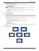
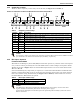
Figure 7 Auxiliary terminal block detail (Monitoring Board)
2.3 Dry Contacts
The UPS provides input dry contacts and output dry contacts.
2.3.1 Input Dry Contacts
There are several input dry contacts at the X3 slot.
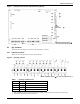
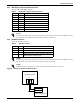
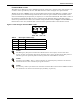
Figure 8 Input dry contacts
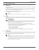
Table 1 Input dry contacts at X3
Position Name Description
J4.1 ENV
3
Battery Room Alarm (N.C.)
J4.2 BtG Battery Ground Fault Detection (N.C.)
J4.3 GEN
1,2
Generator Join Detection (N.O.)
J4.4 +12V +12V Power
1 - Must be configured by configuration software before becoming active.
2 - When activated, the charger current can be limited, via software, to a percentage of the full charger current (0-100%).
3 - Activating this feature turns the battery charger off.
NOTE: The black square ()
on each slot indicates Pin 1.
J3
J1
J13 J21 J25 J28 J4 J26 J30 J10
J22
J23
J12
J9
J15
J17
J24
X4
X4
J16
X1
X2
X3
Intellislot 2
Intellislot 1
Intellislot 3
J8
J2
LCD
BFP INV ACF EPO Dry in MBC BCB
X5
X6
X7
PWR
MODEM
SNMP CARD
NOTE: The black square () on each slot indicates Pin 1.