Liebert NX NXr 8VHU 0DQXDO 30 to 200 kVA UPS cubicles parallelable to 800kVA
Modular NXr UPS 30kVA ~ 200kVA (parallelable to 800kVA) User Manual Version Revision date BOM V1.2 ENPAu 2011 0401 (ENPAu 2011 1108) 31012244 Emerson Network Power provides customers with technical support. Users may contact the nearest Emerson local sales office or service center. Copyright © 2010 by Emerson Network Power Co., Ltd. All rights reserved. The contents in this document are subject to change without notice. Emerson Network Power Co., Ltd. Address: No.1 Kefa Rd.
Safety Precaution This manual covers the installation and use of Emerson NXr UPS. Please read this manual before installation. The NXr UPS must be commissioned and maintained by the engineers designated by the manufacturer or its agent. Failure to observe this could result in personnel safety risk, equipment malfunction and invalidation of warranty. The NXr UPS is only used for commercial or industrial purpose and cannot be used as life support equipment. This is a C2 type UPS product.
Battery voltage higher than 400Vdc All the battery physical maintenance and servicing procedures need special tools or keys and should be carried out only by trained personnel. Take special care when working with the batteries associated with this UPS. When the batteries are connected together, the battery terminal voltage exceeds 400vdc and is potentially leathal.
Contents Chapter 1 Installation Of single UPS cubicle ....................................................................................................................... 1 1.1 Brief Introduction ................................................................................................................................................... 1 1.2 Initial Check .................................................................................................................................................
2.5 Battery Recycling ................................................................................................................................................ 20 2.6 Connection Of External Battery Circuit-Breaker (BCB ........................................................................................ 20 Chapter 3 Installation Of Multiple UPS cubicles ................................................................................................................ 22 3.1 Overview .................
5.2.1 Start Screen............................................................................................................................................. 34 5.2.2 Primary Screen ........................................................................................................................................ 34 5.2.3 Default Screen ......................................................................................................................................... 35 5.3 Selecting Language ...
8.8 Efficiency, Heat Losses And Air Exchange ......................................................................................................... 54 Appendix 1 Option List ...................................................................................................................................................... 55 Appendix 2 List Of Abbreviations ......................................................................................................................................
Chapter 1 Installation Of UPS Module 1 Chapter 1 Installation Of single UPS cubicle This chapter introduces the installation of Emerson NXr 30kVA ~ 200kVA UPS (hereinafter referred to as UPS) module, including the initial check, location selection, positioning, external protective device and cable connection. 1.1 Brief Introduction This chapter briefs the relevant requirements that must be considered in the location selection and cabling of the UPS and relevant equipment.
2 Chapter 1 Installation Of UPS Module 1.3 Location Selection 1.3.1 UPS Room The UPS is designed for indoor installation. It should be installed in a clean environment with adequate ventilation to keep the environmental parameters within the specified operating range (see Table 8-2). For example, the UPS should not be installed in an environment outside the specified operating range, like in thruway tunnels or outdoor places without air-conditioning. The UPS uses forced cooling by internal fans.
Chapter 1 Installation Of UPS Module 3 1.4 Positioning To prolong the service life, the place chosen should offer: convenient wiring space for easy operation on UPS sufficient air exchange to dispel heat produced by UPS protection against atmospheric agents protection against excessive humidity and heat sources protection against dust compliance with fire prevention requirements operating environment temperature between 20°C and 25°C (the typical temperature range for max.
4 Chapter 1 Installation Of UPS Module 843 843 600 1400 1396 350 586 Side view 80 Front view 1400 1397 645 800 794 100 145 102 476 A Top view 445 Anchor hole Bottom view 15 35 A amplified view Figure 1-1 30kVA~160kVA UPS installation dimensions (unit: mm) NXr UPS Module And Parallel System 30kVA ~ 200kVA User Manual
Chapter 1 Installation Of UPS Module 5 825 843 843 600 600 1600 1598 1598 350 80 586 586 Front view 前视图 Side view 侧视图 1400 645 803 100 146 474 A Anchor hole Bottom view 15 顶视图 Top view 445 35 A amplified view Figure 1-2 200kVA UPS installation dimensions (unit: mm) 1.4.6 Cable Entry The UPS uses top cable entry and bottom cable entry. 1.5 External protective device External circuit breakers or other protective devices must be fitted at the input AC supply of the UPS.
6 Chapter 1 Installation Of UPS Module 1.5.1 Rectifier And Bypass Input Over currents Install suitable protective devices in the distribution of the incoming mains supply, considering the power cable current-carrying capacity and overload capacity of the system (see Table 8-6). Generally, magnetic circuit breaker with IEC60947-2 tripping curve C (normal) at 125% of the current listed in Table 1-1 is recommended.
Chapter 1 Installation Of UPS Module 7 2. Non-linear loads (switch mode power supplies) affect the design of the output and bypass neutral cables. The current circulating in the neutral cable may exceed that of the nominal phase current by up to 70%. 3. Values shown for 30 x 6-cell 12V blocks per battery string. Each string may contain from 30 to 40 x 6-cell 12V blocks. Inverse proportional values apply with more blocks per battery string. E.g.
8 Chapter 1 Installation Of UPS Module To user safety earth PE oA oB UPS oC UPS output oN mA Power cable mB mC Main input mN Bypass module bA bB bC Bypass input bN J7 3 Input 4 EXT J9 1 2 3 4 External EPO J10 1 2 3 1 2 3 4 BFP_O BFP_S 12V EXT_Q3 BFP_C IN_S J5 EXT_OUT BPS GND J6 EPO_NC 12V 12V EPO_NO 1 2 4 3 Output BAT+ N BAT- DRV FB OL GND 4 ENV BIG Battery input +12V BAT_OUT GND BAT 1 2 J8 2 3 4 Figure 1-3 UPS electrical connection 1.
Chapter 1 Installation Of UPS Module Figure 1-4 30kVA (NXr 30K-B) UPS power terminals NXr UPS Module And Parallel System 30kVA ~ 200kVA User Manual 9
10 Chapter 1 Installation Of UPS Module mA mB mC mN mN BAT+ BAT N BAT- oA PE bA bB oB bC oN Note: 1. Main input: mA, mB, mC, mN 2. Bypass input: bA, bB, bC, mN 3. UPS output: oA, oB, oC, oN 4. Battery input: BAT+, BAT-, BAT N 5. Earth: PE Figure 1-5 30kVA (NXr 30K) ~ 160kVA UPS power terminals mN mA mB mC + N - oN oA oB bA bB bC oC PE Note: 1. Main input: mA, mB, mC, mN 2. Bypass input: bA, bB, bC, mN 3. UPS output: oA, oB, oC, oN 4. Battery input: + , - , N 5.
Chapter 1 Installation Of UPS Module 11 3. Connect the protective earth cable and all other necessary earth cables to the earth terminals (PE). Note The earth cables and neutral line connection must be in accordance with local and national codes of practice. 4. Identify and make power connections for the input cables according to one of the following two procedures, depending on the type of installation.
12 Chapter 1 Installation Of UPS Module 1.7 Control Cables And Communication As shown in Figure 1-7, the bypass module provides dry contact ports (J5 ~ J10), service and communication ports (RS485 port, RS232 port and three Intellislot (Network Interface/Relay ports) on the front panel.
Chapter 1 Installation Of UPS Module 1.7.2 Battery Circuit-Breaker (BCB) Port J6 is the BCB port. The port is shown in Figure 1-9 and described in Table 1-3. 12V 12V 12V Figure 1-9 Table 1-3 Position Name J6.1 DRV J6.2 FB J6.3 GND J6.4 OL DRV FB OL GND J6 BCB port BCB port description Description BCB driver signal – BCB aux contact for BCB UV coil when used closed to J6.3 when BCB is open Power ground BCB on line – enables J6.1 and J6.2 (when J6.4 is closed to J6.
14 Chapter 1 Installation Of UPS Module 1.7.4 Backfeed protection Output Dry Contact Port J5 is the output dry contact port, providing two relay output dry contact signals. The port is shown in Figure 1-12 and described in Table 1-5. The shunt trip coil of the external circuit breaker can be driven directly through this dry contact rated for 24Vdc/5A. Figure 1-12 Table 1-5 Position BFP_O BFP_S BFP_C J5 Output dry contact port Description of output dry contact port Name Description J5.
Chapter 1 Installation Of UPS Module 15 1.7.
16 Chapter 2 Battery Chapter 2 Battery This chapter introduces the relevant information of the battery, including the brief introduction, battery safety, battery power cables, battery maintenance and recycling, reference current and connection of external BCB. 2.1 Brief Introduction The UPS battery string consists of battery cells (or blocks) connected in series to provide a d.c. input voltage for the UPS inverter to operate.
Chapter 2 Battery 17 2.2 Safety Take special care when working with the batteries associated with the UPS. When all the cells are connected together, the battery string voltage can be up to 576Vdc and is potentially lethal. Please follow the precautions for high voltage operation. Only qualified personnel are allowed to install and maintain the battery.
18 Chapter 2 Battery 2.3 Battery Power Cable 2.3.1 Overview Please install and connect the batteries according to the following description and graphic presentation. 2.3.2 Battery Installation 1. Before installation, check the battery appearance to ensure that there is no damage, inspect and count the accessories, and carefully read this manual and the user manual or installation instruction provided by the battery manufacturer. 2.
Chapter 2 Battery Battery Battery compartment Battery 46.7 Battery 46.7 Battery 384 126.5 External battery cable connection 40 Figure 2-1 Lead out the battery neutral cable from here on the third layer Red Red Black Black Battery Battery Blue Blue Battery 46.7 Battery Battery Battery Battery Battery Battery 46.7 Battery 19 Separator Battery Figure 2-2 Internal battery cable connection (NXr 30K-B) 2.
20 Chapter 2 Battery 2.5 Battery Recycling If the battery leaks electrolyte, or is otherwise physically damaged, it should be placed in a container resistant to sulfuric acid and disposed of in accordance with local regulations. Disused lead-acid storage battery belongs to dangerous waste, and it is a key item for disused battery pollution control.
Chapter 2 Battery + NN NN - - N N UPS UPS Connections between battery, 4-pole BCB and UPS (4 wires at battery side) N N Figure 2-4 UPS UPS + NN Figure 2-3 21 Connections between battery, 3-pole BCB and UPS (3 wires at battery side, + NN N N UPS UPS + Figure 2-5 Connections between battery, 4-pole BCB and UPS (3 wire at battery side Figure 2-6 below shows connections to be carried out when using the UV trip controlled BCB box (containing a BCB and a BCB control board) made by
22 Chapter 3 Installation Of Parallel System Chapter 3 Installation Of Multiple UPS cubicles This chapter details the installation and wiring of a system containing more than one UPS cubicles installed in either parallel and / or dual bus configuration. 3.1 Overview Up to four UPS units can be connected in parallel to form a parallel system. Further, single or parallel configurations can form systems with independent output buses (“dual bus systems”).
Chapter 3 Installation Of Parallel System 23 3.2.1 Cabinet Installation Position the UPS cubicles side by side and make connection as shown in Figure 3-2. The output distribution consisting of external UPS output switches and maintenance bypass must be installed, as shown in Figure 3-2, to facilitate maintenance and system testing.
24 Chapter 3 Installation Of Parallel System Qin UPS 1 Qin UPS 2 Qin Ext Byp Qin UPS 3 Supplied by others Mains input L1, L2, L3, N L1, L2, L3, N Bypass input L1, L2, L3 L1, L2, L3, N Bypass input Mains input L1, L1, L2, L3, N L2, L3, N Bypass input Mains input L1, L1, L2, L3, N L2, L3, N Rectifier Rectifier Rectifier STS STS STS Inverter Inverter Inverter UPS 1 output L1, L2, L3, N UPS 2 output Qout UPS 2 Qout UPS 1 L1, L2, L3, N UPS 3 output Qout UPS 3 Qout Byp Qout of all UPSs
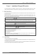
Chapter 3 Installation Of Parallel System 25 3.2.4 Auxiliary Control Wiring Auxiliary wiring must be installed as shown in Figure 3-4 to protect the system and enable a single UPS to be isolated and tested during service. Refer to 1.7.3 Maintenance Switch And Output Switch State Port for auxiliary contact details. Input distribution UPS 1 J9 UPS 2 J9 1 4 3 UPS 3 J9 1 4 3 1 4 3 Q2Ext Q2Ext Q1Ext QUPS QByp Distribution panel To load Figure 3-4 Auxiliary control wiring 3.2.
26 Chapter 3 Installation Of Parallel System J2 J3 J4 Figure 3-6 Locations of ports J2, J3 and J4 on bypass module 3.3 Dual Bus System 3.3.1 Cabinet Installation A dual bus system consists of two independent UPS systems, each containing one or more (maximally 4) parallel UPS modules, as shown in Figure 3-7. The dual bus system has high reliability and is suitable for load with multiple input terminals.
Chapter 3 Installation Of Parallel System UPS 1 UPS 2 Bypass module UPS 3 Bypass module UPS 4 Bypass module Bypass module J2 J2 J2 J2 J3 J3 J3 J3 J4 J4 J4 J4 LBS cable LBS cable Figure 3-8 Connection of typical dual bus system NXr UPS Module And Parallel System 30kVA ~ 200kVA User Manual 27
28 Chapter 4 Operation Chapter 4 System Description This chapter introduces the information related to UPS operation, including the brief introduction, 1+N parallel system, operation mode, battery management and battery protection. Warning: hazardous mains and battery voltage present behind covers No user-serviceable parts are located behind covers that require a tool for their removal. Only qualified service personnel are authorised to remove such covers. 4.
Chapter 4 Operation 29 inverter frequency track that of the static bypass supply, provided that the bypass remains within an acceptable frequency window. A manually-controlled maintenance bypass supply is incorporated into the UPS design. It enables the critical load to be powered from the maintenance bypass supply while the UPS is shut down for routine maintenance and repair.
30 Chapter 4 Operation 4.3.1 Normal Mode The UPS rectifier derives power from the AC mains input source and supplies DC power to the inverter, which continuously supplies the AC load to the load. Simultaneously, the charger, which derives power from the rectifier, float or boost charges the associated backup battery of the UPS. 4.3.2 Battery Mode The UPS is operating in battery mode when the battery is supplying backup power to the load through the inverter.
Chapter 4 Operation 31 The float charge voltage can be set as required by the type of battery. For VRLA batteries, the float charge voltage should be between 2.2V/cell and 2.3V/cell. 4. Float charge temperature compensation (optional). The temperature compensation coefficient can be set as required by the type of battery. 5. EOD protection. When the battery voltage drops to the EOD voltage, the battery converter shuts down automatically and the battery is isolated to avoid further battery discharge.
32 Chapter 5 Operator Control And Display Panel Chapter 5 Operator Control And Display Panel This chapter expands the functions and use of the components on the operator control and display panel of the UPS, provides LCD display information, including the LCD screen types, detailed menu messages, prompt windows and UPS alarm list, and tells how to select language and change the current data and time. 5.1 Introduction The operator control and display panel is located on the front door of the UPS.
Chapter 5 Operator Control And Display Panel Indicator Battery indicator Bypass indicator Inverter indicator Output indicator Status indicator State 33 Description Solid green Load on battery Flashing green Battery EOD pre-warning Solid red Battery abnormal (failed, absent or polarity reversed) or battery converter abnormal (failed, overcurrent or overtemperature) Off Battery and battery converter normal, battery charging Solid green Load on bypass Solid red Bypass power abnormal or outs
34 Chapter 5 Operator Control And Display Panel Providing 320 × 240 dot matrix graphic display, the user-friendly and menu-driven LCD allows you to easily browse through the input, output, load and battery parameters of the UPS, learn current UPS status and alarm information, perform functional setting and control operation. The LCD also stores up to 1024 historical records that can retrieve for reference and diagnosis. 5.2 LCD Screen Type 5.2.
Chapter 5 Operator Control And Display Panel 35 5.2.3 Default Screen During UPS operation, if there is no alarm within two minutes, the default screen will appear, as shown in Figure 5-4. After a short delay, the LCD backlight will turn off. Pressing any menu keys (F1 ~ F5) restores the default screen.
36 Chapter 5 Operator Control And Display Panel System information window The system information window displays the current time, UPS name, configuration and alarm silencing state. This window requires no user operation. For details, see Table 5-6. Table 5-6 Item discription of system information window Item Explanation UPS name Current time (format: 24 hours, hour, minute, second) Unit 1 Liebert NXr 12:30:36 1# / Audible alarm enabled or disabled.
Chapter 5 Operator Control And Display Panel Menu Item Display contrast Date format set Date & time Comm1 baud rate Settings (refer to Intellislot configuration procedure for recommended settings) Comm2 baud rate Comm3 baud rate Communication address Communication mode Callback times Phone No.1 Phone No.2 Phone No.
38 Chapter 5 Operator Control And Display Panel Prompt OK Please check the current warnings Enter control password Battery Self Test aborted, conditions not met Battery Refresh Charge aborted, conditions not met Meaning Check the active alarm messages Required for battery or UPS test (default: 123456) Battery selt-test condition is not met.
Chapter 5 Operator Control And Display Panel Alarm Inverter Asynchronous Inverter fault Fan fault Bypass STS Fail Output Fuse Fail Control power 1 fail Unit Over load System Over load Unit Over load Timeout Byp.
40 Chapter 5 Operator Control And Display Panel Alarm Manual Turn On Manual Turn Off EPO Interrupted Transfer Confirm Transfer Cancel Unit Risk Off Confirm Parallel System Risk Off Confirm Fault Reset Alarm Silence Turn On Fail Audible Alarm Reset Bypass Mode Normal Mode Battery Mode Source share mode UPS Shutdown BCB Open BCB Close Batt. Float Charging Batt. Boost Charging Battery Discharging Battery Period Testing Batt.
Chapter 6 Operating Instructions 41 Chapter 6 Operating Instructions This chapter provides detailed operating procedures of the UPS. The audible alarm may annunciate at various points in these procedures. Pressing the SILENCE ON/OFF button can cancel the audible alarm at any time. Warning: hazardous mains and/or battery voltage present behind protective cover The components that can only be accessed by opening the protective cover with tools cannot be operated by user.
42 Chapter 6 Operating Instructions Maintenance switch Figure 6-2 Location of maintenance switch of 30kVA (NXr 30K) ~ 160kVA UPS Maintenance switch Figure 6-3 Location of maintenance switch of 200kVA UPS 6.2 UPS Startup Procedures It is assumed that the installation is complete, the system has been commissioned by authorized personnel, and the external power isolators are closed.
Chapter 6 Operating Instructions 43 6.2.1 Procedures For Startup Into Normal Mode Warning 1. These procedures result in mains voltage being applied to the UPS output terminals. 2. If any load equipment is connected to the UPS output terminals, check with the user that it is safe to apply power. If the load is not ready to receive power, ensure that it is safely isolated from the UPS output terminals. 3.
44 Chapter 6 Operating Instructions After step 2, if any of the following conditions occurs, open the BCB or confirm that the BCB has tripped automatically and is open. The system can be started up one minute later. EPO action Fault in system commissioning 3. Press and hold the INVERTER ON button on the operator control and display panel for 2s, and the UPS begins to operate in battery mode. 6.3 Procedures For Transfer Between Operation Modes 6.3.
Chapter 6 Operating Instructions 45 maintain the UPS. Caution When the UPS is in maintenance mode, the load is not protected against abnormal mains supply. 6.4 Procedures For Completely Powering Down The UPS Caution The following procedures will switch off all power to the load. Warning: hazardous battery voltage The UPS battery and connecting terminals remain energized at hazardous voltage levels at all times. The following procedures are used to completely power down the UPS and load.
46 Chapter 6 Operating Instructions Warning: hazardous battery voltage The UPS battery and connecting terminals remain energized at hazardous voltage levels at all times. The following procedures are used to isolate one UPS from a parallel system. 1. Press the EPO switch of the UPS to be isolated. 2. Open the external a.c .input switch and BCB of the UPS. In split bypass configuration, it is required to open both external a.c input switches. At this point, other UPSs report Parallel Comm.
Chapter 6 Operating Instructions 47 after the mains power is restored if Auto Recovery after EOD Enabling is enabled after the Auto Recovery after EOD Delay Time expires (the default delay is 10min). during the automatic recovery delay, the UPS will charge its batteries to provide a safety margin for equipment shutdown if input power fails again If the Auto Recovery after EOD Enabling feature is disabled, the user may restart the UPS manually by pressing the FAULT CLEAR button. 6.
48 Chapter 7 Service Chapter 7 Service This chapter introduces the UPS service, including the service procedures of the power module and bypass modules, and the replacement procedures of the air filters. Warning: hazardous mains and/or battery voltage present behind protective cover 1. The components that can only be accessed by opening the protective cover with tools cannot be operated by user. Only qualified service personnel are authorised to remove such covers. 2.
Chapter 7 Service 49 1. Press and hold the INVERTER OFF button on the operator control and display panel for two seconds to manually turn off the inverters, and the UPS transfers to bypass mode. 2. Close the maintenance bypass, and the UPS transfers to maintenance mode. 3. Open the external a.c UPS output switch and input switch. In split bypass configuration, it is required to open external a.c both input switches. 4. Press the EPO switch, ensure that the battery current is 2A.
50 Chapter 7 Service Fixing screw Fixing bar Fixing bar Air filter Figure 7-2 Replacing air filter of 200kVA UPS NXr UPS Module And Parallel System 30kVA ~ 200kVA User Manual
Chapter 8 Product Specifications 51 Chapter 8 Product Specification The chapter provides the UPS specifications. 8.1 Conformity And Standards The UPS has been designed to conform to the European and international standards listed in Table 8-1.
52 Chapter 8 Product Specifications 8.4 Electrical Characteristics (Input Rectifier) Table 8-4 Item Unit Rated AC input voltage1 Input voltage range2 Frequency2 Power factor Input power Vac Vac Hz kW/kVA, full load (half load) kVA rated3 (maximum4) Input current A rated 3 (maximum4) Rectifier AC input (mains) Rated power (kVA) 30 40 60 90, 100 120 150, 60 200 380/400/415 (3-phase and sharing neutral with the bypass input) 228 ~ 437 50/60 (tolerance: 40Hz ~ 70Hz) 0.99 (0.98) 30 (34.
Chapter 8 Product Specifications 53 Note: 1. At low input voltage the UPS recharge capability increases with load decrease (up to the maximum capacity indicated). 2. Max currents listed are for EOD voltage of 1.67V/cell for 240 cells 3.Need to satisfy DC bus voltage for inverter operation of 300-576 Vdc. 8.
54 Chapter 8 Product Specifications Item Unit Bypass voltage tolerance %Vac Rated power (kVA) Upper limit: +10, +15 or +20, default: +15 Lower limit: -10, -20, -30 or –40, default: -20 (delay time to accept steady bypass voltage: 10s) Bypass frequency % ±10 or ±20, default: ±10 tolerance Synchronisation window Hz Rated frequency: ±5 Note: 1. Factory set to 380V. 400V or 415V selectable by commissioning engineer. 2. Factory set to 50Hz. 60Hz selectable by commissioning engineer 8.
Appendix 1 Option 55 Appendix 1 Option List Table 1 Option Dry contact card SIC card UF-RS485 card Modbus card Battery temperature sensor Air filter Model UF-DRY310 UF-SNMP810 UF-RS485 UFMOD41Z1 UF-SENSOR LBS cable (5m, 10m, 15m) Parallel control cable (5m, 10m, 15m) Bypass load sharing inductor Bypass load sharing inductor Bypass load sharing inductor Bypass load sharing inductor UF-NRBYPCK-30 UF-NRBYPCK-100 UF-NRBYPCK-160 UF-NRBYPCK-200 Option list BOM No.
56 Chapter 8 Product Specifications Appendix 2 List Of Abbreviations Abbreviation Description UPS Uninterruptible power system AC Alternating current DC Direct current SCR Silicon-controlled rectifier RCCB Residual current circuit breaker RCD Residual current detector RFI Radio frequency interference EOD End-of-discharge CSA Cross sectional area PE Protective Earth SCR Silicon-controlled rectifier EPO Emergency power off MCCB Moulded-case circuit breaker CT Center tap BCB Ba