
Specifications

IB-106-340
6-5
5 Remove the first calibration gas
and apply the second calibration
gas. (Electronics will abort the
calibration if step 6 is not done
within 30 minutes).
6 Push the CAL key; the CAL LED
will be on solid. The timer is acti-
vated for the second calibration
gas flow. When the timer times
out, the CAL LED will flash a 2
pattern flash or a 3 pattern flash (2
pattern flash equals a valid cali-
bration, 3 pattern flash equals an
invalid calibration).
If the slope or the constant is out
of specification, a diagnostic alarm
LED will be flashing. The diag-
nostic alarm will remain active
until the purge cycle is over. If the
three pattern flash occurs without
a diagnostic alarm, the calibration
gases could be the same or the
calibration gas was not turned on.
The CAL LED flashing indicates
the calibration is done. (See Sec-
tion V, TROUBLESHOOTING,
for an explanation of the 2 pattern
and 3 pattern flashes).
7 Remove the second calibration gas
and cap off the calibration gas
port.
8 Push the CAL key; the CAL LED
will be on solid as the unit purges.
(Default purge time is three min-
utes). When the purge is com-
plete, the CAL LED will turn off
and the Oxymitter 4000 output
unlocks from its held value and
begins to read the process O
2
.
If the calibration was valid, the
DIAGNOSTIC ALARMS
LEDs will
indicate normal operation. If the new
calibration values, slope or constant, is
not within the parameters, the
DIAGNOSTIC ALARMS LED will
indicate an alarm. (See Section V,
TROUBLESHOOTING, for alarm
codes). If the calibration was invalid,
the Oxymitter 4000 will return to
normal operation, as it was before a
calibration was initiated, and the
parameters will not be updated.
(e) Place control loop in automatic.
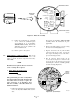
6-3. LED STATUS INDICATORS.
a. Diagnostic/Unit Alarms.
Table 6-1 lists the
types and status of alarms that will be encoun-
tered. (See Section V, TROUBLESHOOTING,
for a detailed description of each fault).
b.
When the electronics determines a calibration is
recommended, the CALIBRATION RECOM-
MENDED LED is on solid.
c.
The CAL LED turns on when a calibration is
recommended and is on during the calibration
process. During calibration, the CAL LED can
be flashing, which would indicate operator action
is requested, or on solid, which indicates calcu-
lations and measurements are in progress.
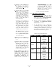
Table 6-1. Diagnostic/Unit Alarms.
LED FLASHES STATUS FAULT
1OPEN1
HEATER T/C 2 SHORTED 2
3 REVERSED 3
4
A/D COMM
ERROR
4
1OPEN5
2 HIGH HIGH TEMP 6
HEATER 3 HIGH CASE TEMP 7
4LOW TEMP8
5HIGH TEMP9
1HIGH mV10
O2 CELL 3 BAD 11
4EEPROM
CORRUPT
12
CALIBRATION 1 INVALID SLOPE 13
2INVALID
CONSTANT
14
3
LAST
CALIBRATION
FAILED
15