
Specifications

IB-106-340
6-7
2. Replace.
(a) Bolt the Oxymitter 4000 to the stack
and install insulation.
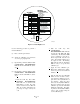
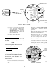
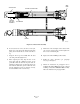
(b) Insert the logic I/O and 4-20 mA leads
in the signal port and connect to the
logic I/O and 4-20 mA screw terminals
(Figure 6-4).
(c) Insert the power leads in the AC line
voltage port and connect to the AC line
screw terminals. Connect the line, or
L1, wire to the L1 terminal, and the
neutral, or L2, wire to the N terminal.
Slide the AC terminal cover over the
terminal connection and tighten the
cover screw.
(d) Install left housing cover (27, Figure
6-1) and ensure it is tight. Secure the
cover using cover lock (34), gasket
(33), and screw (32).
(e) Connect the calibration gas and
instrument air lines to the Oxymitter
4000.
(f) Turn on the calibration gases at the
cylinders and turn on instrument air.
(g) Restore power to the system.
b. Oxymitter 4000 (with Integrally Mounted
SPS 4000).
1. Remove.
(a) Turn off power to the system.
(b) Shut off the calibration gases at the
cylinders and the instrument air.
(c) Disconnect the instrument air and
calibration gas lines from the SPS 4000.
If the instrument air does not flow
through the SPS 4000, disconnect the
instrument air directly at the Oxymitter
4000.
(d) Remove the screws securing the ter-
minal cover to the SPS 4000 manifold.
Remove the terminal cover to expose
the terminal strip.
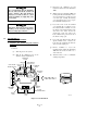
(e) Tag all customer-wired leads that are
connected to the terminal strip before
removing.
(f) On the terminal strip, loosen the
screws securing the customer-wired
LINE IN and NEUTRAL leads to
terminals L and N (Figure 2-10).
Also, remove the customer-wired
ground lead from the ground lug.
Remove the leads from the terminal
strip and slide them from the manifold
through the line voltage conduit port.
(g) Next, loosen the screws of remote
contact input terminals 1 and 2; 4-
20 mA terminals 3 and 4; and relay
output terminals 7, 8, 9, and 10. Re-
move the leads from the terminal strip
and slide them from the manifold
through the signal conduit port.
(h) Remove insulation to access the
mounting bolts. Unbolt the Oxymitter
4000/SPS 4000 assembly from the
stack and take the entire assembly to a
clean work area.
(i) Allow the unit to cool to a comfortable
working temperature.
2. Replace.
(a) Bolt the Oxymitter 4000/SPS 4000
assembly to the stack and install insu-
lation.
(b) Follow the instructions in paragraph
2-3 to connect the line voltage and
signal leads to an Oxymitter 4000/
SPS 4000 assembly.