
Specifications

IB-106-340
6-12
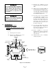
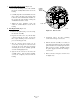
CERAMIC SUPPORT ROD
CELL FLANGE
CERAMIC
DIFFUSER
ASSEMBLY
V-DEFLECTOR
HEATER
WIRE
LOOP
22220050
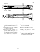
Figure 6-8. Heater Strut Assembly
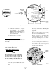
d.
Loosen, but do not remove, the three screws (30,
Figure 6-1) on the strut in the finned housing. The
spring tension should release and the strut moves
up.
e.
Grasp the wire loop and carefully slide the strut
out of the probe tube (Figure 6-8).
f.
When replacing the strut, align the slot on the
heater plate with the calibration gas line in the
probe tube. Slide the strut into the probe tube. It
will turn to align the hole on the back plate of the
strut with the calibration gas line. When the hole
and the calibration gas line are aligned correctly,
the strut will slide in the rest of the way.
g.
Push down on the back plate of the strut to make
sure you have spring tension and then tighten the
three screws on the back plate.
h.
Replace the CAL and REF gas silicon tubes.
i.
Install the entire electronics per paragraph
6-5a, steps 7 through 13.
j.
Follow the instructions in paragraph 6-4a2 to
install the Oxymitter 4000 into the stack or duct. If
installing an Oxymitter 4000/SPS 4000 assembly,
follow the instructions in paragraph 6-4b2.