
Specifications


IB-106-340
6-19
When installing a solenoid, do not over-
tighten. Damage to the solenoid may occur.
When installing the pressure switch, do
not overtighten. Damage to the solenoid
may occur.
Do not use fingers to release valve stem.
The valve may release air at high pres-
sures and cause injury.
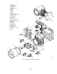
6. Being careful not to disconnect the board
wiring, carefully lift the board and spacer
assembly from manifold (5) and set aside. Do
not lose O-rings (8) from the bottom of
spacers (9).
7. Tag and unplug solenoid (13 or 20) leads
from power supply board (18). Refer to
Figure 6-12. Calibration gas 1 solenoid wires
connect to connector J5, and calibration gas 2
solenoid wires connect to connector J4.
8. Remove the top nut of solenoid (13 or 20,
Figure 6-11) securing the coil assembly and
washer to the base. Remove the coil
assembly, including the leads, and washer.
Place a 13/16 in. deep socket over the
solenoid base and remove.
9. Install the new solenoid base. Be careful not
to overtighten. Install the new washer and
coil assembly and secure with the top nut.
Connect the leads to the proper connector on
power supply board (18). Refer to Figure
6-12 if necessary.
10. Carefully install the board and spacer
assembly into manifold (5, Figure 6-11) by
aligning spacers (9) with the mounting holes
on the manifold and securing with screws
(11). Ensure O-rings (8) are installed
between the spacers and the manifold
surface.
11. Install manifold cover (14), and secure with
manifold cover lock (6) and screw (7).
12. Turn on the calibration gases at the cylinders.
d. Pressure Switch Replacement.
Use the
following procedure to replace pressure switch
(12, Figure 6-11).
1. Turn off power to the system.
2. Shut off the calibration gases at the cylinders.
3. Remove screw (7) securing manifold cover
lock (6) and remove the lock.
4. Remove manifold cover (14).
5. Remove two screws (11) attaching spacers
(9) to manifold (5).
6. Being careful not to disconnect the board
wiring, carefully lift the board and spacer
assembly from manifold (5) and set aside. Do
not lose O-rings (8) from the bottom of
spacers (9).
7. Tag and remove the leads from pressure
switch (12).
8. Place a 1-1/16 in. 6-point socket over
pressure switch (12) and remove.
9. Install new pressure switch (12). Be careful
not to overtighten. Connect the leads to the
proper terminals on the pressure switch.
10. Carefully install the board and spacer
assembly into manifold (5) by aligning
spacers (9) with the mounting holes on the
manifold and securing with screws (11).
Ensure o-rings (8) are installed between the
spacers and the manifold surface.
11. Install manifold cover (14), and secure with
manifold cover lock (6) and screw (7).
12. Turn on the calibration gases at the cylinders.
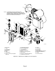
e. Check Valve Replacement.
Check valve (19,
Figure 6-13) may stick or become plugged over
time. Replace when necessary. If condensation
deposits are noted upon removal, consider
insulating the check valve.
f. Pressure Regulator (Optional) Maintenance.
1. Pressure Adjustments. Reference air
pressure regulator (8, Figure 6-13) is factory
set to 20 psi (138 kPa). Adjust using the knob
on top of the pressure regulator if necessary.
2. Condensation Drain. To drain excess mois-
ture from the filter bowl of reference air
pressure regulator (8), use a screwdriver or
comparable tool to periodically release valve
stem on the bottom of the regulator.