
Specifications


IB-106-340
4-1
SECTION IV. OPERATION
4-1. GENERAL.
a. Overview.
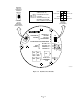
Ensure the Oxymitter 4000 is at
normal operation. The diagnostic LEDs will dis-
play the operating cycle. All other LEDs should
be off (Figure 4-1).
1. DIAGNOSTIC ALARM LEDS. If there is
an error in the system, one of these LEDs
will flash various blink codes (Section V,
TROUBLESHOOTING). In the case of
multiple errors, only one will be displayed
based on a priority system. Correct the
problem and cycle power. The operating
display will return or the next error will be
displayed. The alarms are:
HEATER T/C
HEATER
O2 CELL
CALIBRATION
2. CALIBRATION RECOMMENDED LED.
Turns on when the system determines a cali-
bration is recommended.
3. TEST POINTS. Test points 1 through 6
will allow you to monitor with a multimeter:
the heater thermocouple, O
2
cell millivolt,
and the process O
2
.
(
a) TP1 and TP2 monitor the oxygen cell
millivolt output which equates to the
percentage of oxygen present.
(b) TP3 and TP4 monitor the heater
thermocouple.
(c) TP5 and TP6 monitor the process gas
or the calibration gas parameter.
4. CAL LED.
The CAL LED is on steady or
flashing during calibration. Further informa-
tion is available in Section VI,
MAINTENANCE AND SERVICE.
5. Keys.
(a) INC and DEC.
The INC and DEC
keys are used to set the values of the
calibration gases. Attach a multimeter
across TP5 and TP6. The calibration
and process gases can now be moni-
tored. Pressing the INC or DEC once
will cause the output to switch from the
process gas to the calibration gas.
Pressing INC or DEC a second time
will increase or decrease the calibra-
tion gas parameter. If the keys have
been inactive for one minute, the out-
put reverts to the process gas. When a
calibration has been initiated, the value
at TP5 and TP6 is the % O
2
seen by the
cell. Oxygen levels, as seen on the
multimeter, are:
8.0% O
2
= 8.0 volts DC
0.4% O
2
= 0.4 volts DC
(b) CAL.
The CAL key can:
1 Initiate a calibration.
2 Sequence through calibration.
3 Abort the calibration.
b. Model 751 Remote Powered Loop LCD
Display (Optional).
Refer to Remote Powered
Loop LCD manual for calibration and operation.