Precision Cooling For Business-Critical Continuity™ Liebert Prop Fan Condensing Unit™ Installation, Operation and Maintenance Manual - 50 & 60Hz
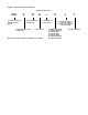
Figure i Model number nomenclature Example: PFH037A-PL7 PFH Prop Fan Condensing Unit with Hot-Gas Bypass 0 37 A Nominal Capacity 1000 BTU/Hr 0 = Standard Noise Level Z =Quiet-Line — P — = Standard Coil C = Coated Coil A = Air Cooled Not all options and/or voltage combinations are available.
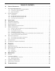
TABLE OF CONTENTS 1.0 PRODUCT DESCRIPTION . . . . . . . . . . . . . . . . . . . . . . . . . . . . . . . . . . . . . . . . . . . . . . . . . . .1 1.1 Prop Fan Condensing Units. . . . . . . . . . . . . . . . . . . . . . . . . . . . . . . . . . . . . . . . . . . . . . . . . . . . 1 1.1.1 1.1.2 1.1.3 1.2 Base System 95°F (35°C) Ambient Models . . . . . . . . . . . . . . . . . . . . . . . . . . . . . . . . . . . . . . . . . 1 105°F (41°C) Ambient Models . . . . . . . . . . . . . . . . . . . . . . . . . . .
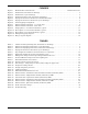
FIGURES Figure i Figure 1 Figure 2 Figure 3 Figure 4 Figure 5 Figure 6 Figure 7 Figure 8 Figure 9 Figure 10 Figure 11 Figure 12 Figure 13 Model number nomenclature . . . . . . . . . . . . . . . . . . . . . . . . . . . . . . . . . . . . . . . . . Inside Front Cover Dimensions, horizontal air discharge . . . . . . . . . . . . . . . . . . . . . . . . . . . . . . . . . . . . . . . . . . . . . . . . 3 Dimensions, top air discharge . . . . . . . . . . . . . . . . . . . . . . . . . . . . . . . . . . . . . . . . .
Product Description 1.0 PRODUCT DESCRIPTION 1.1 Prop Fan Condensing Units Liebert propeller fan condensing units are available in a range of sizes and configurations to offer flexibility in designing a precision environmental control system. The appropriate propeller fan condensing unit paired with a corresponding Liebert fan coil evaporator model such as Liebert DataMate, Liebert Mini-Mate2 or Liebert Challenger 3000 is an effective solution for your environmental control application requirements.
Installation 2.0 INSTALLATION Read this entire installation section before starting installation. This section details dimensional, electrical and piping information and specifications that affect the placement of the PFH unit in relation the connected evaporator unit, other outside units, barriers and walls. Be particularly mindful of service and airflow clearances and maximum equirvalent piping distances and in elevation differences between PFH and connected evaporator unit.
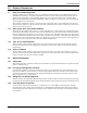
Installation 2.3 Dimensional Data Figure 1 Dimensions, horizontal air discharge Fan Rotation CCW (left side) Removable (right) panel for access to refrigeration component A Right Air Discharge Left Air Intake Shaded area indicates a minimum clearance of 18" (457mm) for proper air flow. B Shaded area indicates a recommended clearance of 24" (610mm) for component access and removal.
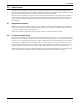
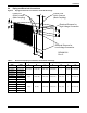
Installation Figure 2 Dimensions, top air discharge Top Air Discharge Guard Height Fan Rotation CW Right Air Intake Shaded area indicates a minimum clearance of 18" (457mm) for proper air flow. Left Air Intake 2" (51mm) Shaded area indicates a minimum clearance of 18" (457mm) for proper air flow Removable panel for access to high-voltage and low-voltage connections and refrigeration components 36-1/8" (918mm) 53-3/16" (1351mm) 4" (102mm) typ. 2" (51mm) typ.
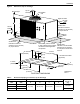
Installation Figure 3 Dimensional data, 277V step-down transformer .31" (8mm) Dia. For rigid mounting and shipping .281" (7mm) Dia. For wall mounting 1/4-20 (2 screws & lock washers) for rigid mounting and shipping 1D18214P1 10.3" (262mm) 1D18214P2 11.68" (297mm) Remove screws & attach bracket 5.5" (140mm) 4.92" (125mm) Access to electrical connections from bottom WALL MOUNTING RIGID MOUNTING Notes: 1. 1D18214P1 = Acme catalog no.
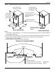
Installation 2.4 Piping and Electrical Connections Figure 4 Piping and electrical connections, horizontal discharge Liquid Line Quick Connect (Male Coupling) Suction Line Quick Connect (Male Coupling) A G F Electrical Entrance for High-Voltage Connection B C Electrical Entrance for Low-Voltage Connection D DPN000132 Rev.
Installation Figure 5 Piping and electrical connections, top air discharge * System 2 (5 Ton) Electrical Entrance for High-Voltage Connection Liquid Line Quick Connect (Male Coupling) Electrical Entrance for Low-Voltage Connection * System 1 (3 Ton) Suction Line Quick Connect (Male Coupling) * System 1 and System 2 on 8 Ton only Table 4 DPN000133 Rev.
Installation Figure 6 General piping arrangement SINGLE CIRCUIT = 1 - 5 Tons DUAL CIRCUIT = 8 Tons Condenser Coil High Pressure Switch Compressor * Liquid Injection Valve Bulb Suction Line Male Quick Connect Coupling Hot Gas Bypass Solenoid Valve 3 - Way Head Pressure Control Valve Hot Gas Bypass Control Valve Pressure Relief Valve Check Valve Sight Glass Liquid Injection Valve Liquid Line Solenoid Valve Liebert Lee-Temp Receiver Receiver Heater Pressure Limiting Pressure Balancing Switch Valve
Installation Figure 7 Electrical field connections, 1- to 5-ton units Single- or three-phase electric service not provided by Liebert Field-supplied unit disconnect switch Field-supplied unit Single- or three-phase disconnect switch electric service not provided by Liebert Field-supplied 24V NEC Class 2 wiring to evaporator module Field-supplied 24V NEC Class 2 wiring to evaporator module Horizontal Air Discharge Models Top Air Discharge Models (5 Ton High Ambient or 5 Ton Quiet-Line) Electric ser
Installation Figure 8 Electrical field connections, 8-ton units Field-supplied unit disconnect switch Single- or three-phase electric service not provided by Liebert Field-supplied 24V NEC Class 2 wiring to evaporator module Electric service connection to contactor or terminal block Factory-wired to components on electric panel Single- or three-phase electric service not provided by Liebert High-voltage electric power supply entrance Heat rejection connection. Field-supplied 24V NEC Class 2 wiring.
Installation Figure 9 Single-phase, 1-3 ton model schematic, typical Conductors Field-Supplied (See Note 5) Unit Alarm Input Connection 24V Power Supply From Unit Min 40 Va HGBP Signal Output Connection 3 3 2 2 BL HP1 W 4 4 HG1 BR 1 See Note 6 BR BK HP2 R 1-Phase Line Voltage Supply By Others (See Notes 1 & 3) C1 BK BR 1 24V Ground NOMENCLATURE OUTDOOR CONDENSING MODULE EVAPORATOR UNIT L1 R BK RHTR HG1 BK 1C1 HGSV BK 2C1 L2 BK BK CHTR BK LLSV R Earth Ground By Others
Installation Figure 10 Three-phase, 3-5 ton model schematic, typical Conductors Field-Supplied (See Note 5) Unit Alarm Input Connection 24V Power Supply From Unit Min 40VA 3 3 2 2 BL HP1 W BK C1 27,29,30 BR HGBP Signal Output Connection 24V Ground 4 4 1 1 BR BR HG1 See Note 6 See Note 1 F1 F2 3-Phase Line Voltage Supply By Others (See Note 3) NOMENCLATURE OUTDOOR CONDENSING MODULE EVAPORATOR UNIT L1 1C1 L2 2C1 L3 3C1 BK TX1 R HP2 27 See Note 7 R BK RHTR1 BK RHTR2 B
Installation Figure 11 Three-phase, 8 ton model schematic, typical Conductors Field-Supplied (See Note 5) Evaporator Unit HIGH HEAD 1 COOLING 1 24V GND HGBP1 COMP1 HIGH HEAD 2 COOLING 2 HGBP2 COMP2 3 3 2 2 10 10 9 9 4 4 1 1 7 7 6 6 8 8 5 5 OUTDOOR CONDENSING MODULE BL See Note 6 HP1 W C1 Aux. R C2 Aux.
Installation 2.5 Piping Considerations The Liebert Mini-Mate2, Liebert DataMate and the 3-ton Liebert Challenger 3000 split system units are designed with quick-connect fittings and are factory-charged to proper refrigerant levels. This permits connecting units without brazing inside critical spaces. These split systems require two refrigerant lines—an insulated copper suction line and a copper liquid line—between the evaporator and condensing units.
Installation Figure 12 Refrigerant piping diagram Pitch down 1/2" (13mm) per 10 ft. (3m) Evaporator NOTE When NOTE installing remote condensing units below the evaporator, the remote suctioncondensing gas line should trapped When installing units be below the with an inverted trap togas theline height of the evaporator. evaporator, the suction should be trapped with This prevents migration to the compresan inverted traprefrigerant to the height of the evaporator . This sors during off cycles.
Installation 2.5.2 Pre-Charged Line Sets Liebert pre-charged line sets are available in 15 ft (4.5m) and 30 ft (9m) lengths (see Table 7). NOTICE Risk of improper handling and installation of pre-charged lines. Can cause kinks and similar damage to lines. Care must be taken to prevent kinking the pre-charged lines for 1-ton and 3.5-ton units. Use tube benders and make all bends before making connections to either end of the precharged pipes.
Installation Table 8 Liebert PFH unit charge levels and coupling size Model Numbers 60 Hz R-407C Charge 50 Hz Coupling Size lb-oz (kg) Liquid Suction 8-6 (3.8) #6 #11 13-5 (6.04) #6 #11 26-10 (12.08) #10 #12 95°F (35°C) Standard Sound PFH014A-_L7 PFH013A-_L7 PFH020A-_L7 PFH019A-_L7 PFH027A-_L7 PFH026A-_L7 PFH037A-_L7 PFH036A-_L7 PFH042A-_L7 PFH041A-_L7 PFH067A-_L7 PFH066A-_L7 PFH096A-_L7 PFH095A-_L7 3-ton Circuit 3-ton Circuit 22-9 (10.
Installation 2.5.4 Installation of Piping to Units NOTE When using hard piping, complete all piping and evacuate the lines before connecting quick-connects. NOTE Liebert Challenger 5-ton evaporator includes a nitrogen holding charge only. This holding charge must be evacuated and unit placed in a 250 micron vacuum prior to connecting piping. See Table 12 for field charge required. Use caution when connecting the quick-connect fittings. Read through the following steps before making the connections. 1. 2.
Installation Remove Existing Condensing Unit 1. Recover refrigerant in system using proper refrigeration practices. 2. Oil removal: The majority of the oil will be in the old condensing unit (compressor, condenser and receiver), which will be replaced with the new unit. 3. Remove high-voltage and low-voltage wiring. NOTE Wiring should be removed by a licensed electrician. Existing low-voltage wiring may have a 3-wire lead. A 4-wire lead is required for hot gas bypass control on the new condensing unit. 4.
Installation 2.5.6 General System Charge Requirements Liebert split system units are designed with quick-connect fittings and are factory-charged to proper levels. Due to the wide range of operating ambients and sensitivity of the system components to charge level, the system charge must be maintained at recommended levels.
Installation 2.6 Electrical Connections Each unit is shipped from the factory with all internal wiring completed. All power, control wiring and ground connections must be made in accordance with the National Electrical Code and local codes. Refer to equipment nameplate regarding wire size and circuit protection requirements. Refer to Figures 5, 7 and 8 and electrical schematic (reference Figures 9 through 11) when making connections.
Installation 2.7 Electrical Data Table 16 Model # 14 20 27 37 42 67 96 * Nominal Capacity Tons 1 1.5 2 3 3.5 5 8 Input Voltage- Phase * Electrical Characteristic 208/230-1 208/230-3 460-3 575-3 FLA 8.4 — — — WSA 10.2 — — — OPD 15 — — — FLA 12.1 — — — WSA 14.8 — — — OPD 25 — — — FLA 13.5 — — — WSA 16.5 — — — OPD 25 — — — FLA 19.3 12.8 6.4 5.9 WSA 23.8 15.7 7.8 7.1 OPD 40 25 15 15 FLA — 15.3 7.1 6.6 WSA — 18.8 8.7 8.
Installation Table 18 Model # 27 37 42 67 * Nominal Capacity Tons 2 3 3.5 5 Input Voltage-Phase * Electrical Characteristic 208/230-1 208/230-3 460-3 575-3 FLA 13.0 — — — WSA 16.0 — — — OPD 25 — — — FLA 18.8 12.3 6.4 5.2 WSA 23.3 15.2 7.8 6.4 OPD 40 25 15 15 FLA — 14.8 6.9 5.9 WSA — 18.3 8.5 7.3 OPD — 30 15 15 FLA — 21.1 10.9 8.8 WSA — 25.9 13.4 10.
Installation Table 21 Model # * 2.8 Electrical data - Quiet-Line models (95°F/35°C) 50Hz Nominal Capacity Tons * Electrical Characteristic Input Voltage-Phase 220-1 200/230-3 380/415-3 13 1 FLA — — — 19 1.5 FLA — — — 26 2 FLA 12.3 — 4.8 36 3 FLA 18.0 — 6.9 41 3.5 FLA — 17.3 8.4 66 5 FLA — 22.5 12.4 95 8 FLA — — — FLA = Full Load Amps Checklist for Completed Installation ___ 1. All items unpacked and checked. ___ 2.
Operation 3.0 OPERATION 3.1 Compressor The scroll compressor is equipped with a band type crankcase heater to resist liquid refrigerant migration into the compressor during the Off cycle. The three-phase scroll compressor requires proper phasing to ensure correct motor rotation. The component connections have been phase synchronized at the factory. Refer to 2.6 - Electrical Connections to verify proper compressor wiring. 3.
Operation 3.4 Hot Gas Bypass 3.4.1 Operation When applying hot gas bypass with split system condensing units, bypassing discharge gas to the compressor suction line offers more flexibility than conventional hot gas bypass to the evaporator unit. The hot gas bypass valve is installed between the compressor discharge piping and suction piping, bypassing the condenser and evaporator coils.
Operation Figure 13 Hot gas bypass diagram 27
Maintenance 4.0 MAINTENANCE 4.1 General Access the condensing unit by removing the unit housing panel. Clean the air cooled condenser coil of all debris that will inhibit airflow. This can be done with compressed air or with a commercial coil cleaner. Check for bent or damaged coil fins and repair as necessary. During winter, do not permit snow to accumulate on or around the condensing unit. Check all refrigerant lines and capillaries for vibration isolation and support as necessary.
Maintenance 4.3 Compressor Replacement Replacement compressors are available from Emerson. They will be shipped in a permanent crate to the job site as required by the service contractor. Upon shipping a replacement compressor, the service contractor will be billed in full for the compressor. Credit for warranty replacement compressors will not be issued until the replacement has been returned to the factory. The compressor should be returned in the same container used for shipping to the job.
Maintenance 4.4 Field Charge Verification An integral sightglass is provided with the receiver to assist in field charge verification. During charge verification set the control temperature down to keep the system running. If the system is equipped with hot gas bypass, de-energize it by removing power from the hot gas solenoid valve coil. To remove power, disconnect the solenoid leads from the unit contactor in the electric box (refer to specific unit schematic; reference Figures 7 through 10).
Troubleshooting 5.
Ensuring The High Availability Of Mission-Critical Data And Applications. Emerson Network Power, the global leader in enabling business-critical continuity, ensures network resiliency and adaptability through a family of technologies—including Liebert power and cooling technologies—that protect and support business-critical systems. Liebert solutions employ an adaptive architecture that responds to changes in criticality, density and capacity.