4801_QIG_RevKB.
4801_QIG_RevKB.fm Page 2 Friday, December 3, 2010 1:17 AM Quick Installation Guide 00825-0100-4801, Rev KB December 2010 Rosemount 3051S © 2010 Rosemount Inc. All rights reserved. All marks property of owner. Rosemount and the Rosemount logotype are registered trademarks of Rosemount Inc. Rosemount Inc. Emerson Process Management GmbH & Co.
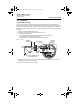
4801_QIG_RevKB.fm Page 3 Friday, December 3, 2010 1:17 AM Quick Installation Guide 00825-0100-4801, Rev KB December 2010 Rosemount 3051S STEP 1: MOUNT THE TRANSMITTER Liquid Flow Applications 1. Place taps to the side of the line. 2. Mount beside or below the taps. 3. Mount the transmitter so that the drain/vent valves are oriented upward. Gas Flow Applications 1. Place taps in the top or side of the line. 2. Mount beside or above the taps. Steam Flow Applications 1. Place taps to the side of the line.
801_QIG_RevKB.fm Page 4 Friday, December 3, 2010 1:17 AM Quick Installation Guide 00825-0100-4801, Rev KB December 2010 Rosemount 3051S STEP 1 CONTINUED...
4801_QIG_RevKB.fm Page 5 Friday, December 3, 2010 1:17 AM Quick Installation Guide 00825-0100-4801, Rev KB December 2010 Rosemount 3051S STEP 1 CONTINUED... Bolting Considerations If the transmitter installation requires assembly of the process flanges, manifolds, or flange adapters, follow these assembly guidelines to ensure a tight seal for optimal performance characteristics of the transmitters. Use only bolts supplied with the transmitter or sold by Emerson as spare parts.
4801_QIG_RevKB.fm Page 6 Friday, December 3, 2010 1:17 AM Quick Installation Guide 00825-0100-4801, Rev KB December 2010 Rosemount 3051S STEP 1 CONTINUED... Figure 2. Torque values for the flange and flange adapter bolts Bolt Material Head Markings Initial Torque Final Torque Carbon Steel (CS) 300 in.-lbs. 650 in.-lbs. 150 in.-lbs. 300 in.-lbs.
4801_QIG_RevKB.fm Page 7 Friday, December 3, 2010 1:17 AM Quick Installation Guide 00825-0100-4801, Rev KB December 2010 Rosemount 3051S STEP 1 CONTINUED... Inline Gage Transmitter Orientation The low side pressure port (atmospheric reference) on the inline gage transmitter is located under the sensor module neck label. (See Figure 3.) Keep the vent path free of any obstruction, including but not limited to paint, dust, and lubrication by mounting the transmitter so that any contaminants can drain away.
4801_QIG_RevKB.fm Page 8 Friday, December 3, 2010 1:17 AM Quick Installation Guide 00825-0100-4801, Rev KB December 2010 Rosemount 3051S STEP 4: CONNECT WIRING AND POWER UP Use the following steps to wire the transmitter: 1. Remove the housing cover labeled “Field Terminals.” 2. Connect the positive lead to the “+” terminal, and the negative lead to the “–” terminal. NOTE Do not connect the power across the test terminals. Power could damage the test diode in the test connection.
4801_QIG_RevKB.fm Page 9 Friday, December 3, 2010 1:17 AM Quick Installation Guide 00825-0100-4801, Rev KB December 2010 Rosemount 3051S STEP 4 CONTINUED... Signal Wiring Grounding Do not run signal wiring in conduit or open trays with power wiring, or near heavy electrical equipment. Grounding terminations are provided on the sensor module and inside the Terminal Compartment. These grounds are used when transient protect terminal blocks are installed or to fulfill local regulations.
4801_QIG_RevKB.fm Page 10 Friday, December 3, 2010 1:17 AM Quick Installation Guide Rosemount 3051S 00825-0100-4801, Rev KB December 2010 STEP 4 CONTINUED... Remote Display Wiring and Power Up The Remote Mount Display and Interface system consists of a local transmitter and a remote mount LCD display assembly. The local 3051S transmitter assembly includes a Junction Box housing with a three position terminal block integrally mounted to a sensor module.
4801_QIG_RevKB.fm Page 11 Friday, December 3, 2010 1:17 AM Quick Installation Guide 00825-0100-4801, Rev KB December 2010 Rosemount 3051S STEP 4 CONTINUED... Intrinsic Safety Consideration: The transmitter assembly with remote display has been approved with Belden 3084A DeviceNet cable. Alternate cable may be used as long as the transmitter with remote display and cable is configured according to the installation control drawing or certificate.
4801_QIG_RevKB.fm Page 12 Friday, December 3, 2010 1:17 AM Quick Installation Guide 00825-0100-4801, Rev KB December 2010 Rosemount 3051S STEP 4 CONTINUED... NOTE Wire colors provided on page 11 are per Belden 3084A DeviceNet cable. Wire color may vary depending on cable selected. Belden 3084A DeviceNet cable includes a ground shield. This shield must be connected to earth ground at either the sensor module or the Remote Display, but not both.
4801_QIG_RevKB.fm Page 13 Friday, December 3, 2010 1:17 AM Quick Installation Guide 00825-0100-4801, Rev KB December 2010 Rosemount 3051S STEP 4 CONTINUED... Conduit Electrical Connector Wiring (Option GE or GM) For 3051S transmitters with conduit electrical connectors GE or GM, refer to the cordset manufacturer’s installation instructions for wiring details.
4801_QIG_RevKB.fm Page 14 Friday, December 3, 2010 1:17 AM Quick Installation Guide 00825-0100-4801, Rev KB December 2010 Rosemount 3051S STEP 5: VERIFY CONFIGURATION Use any HART-compliant master to communicate with and verify configuration of the 3051S. For the HART Diagnostics transmitter (option code DA1), DD revision 3051S HDT Dev. 1 Rev. 1 is required. Field Communicator User Interface The Traditional Interface - Device Revision 6 or 7 and DD Revision 7 Fast Key Sequence can be found on page 15.
4801_QIG_RevKB.fm Page 15 Friday, December 3, 2010 1:17 AM Quick Installation Guide 00825-0100-4801, Rev KB December 2010 Rosemount 3051S A check (⻫) indicates the basic configuration parameters. At a minimum, these parameters should be verified as part of the configuration and startup procedure. Table 1.
4801_QIG_RevKB.fm Page 16 Friday, December 3, 2010 1:17 AM Quick Installation Guide 00825-0100-4801, Rev KB December 2010 Rosemount 3051S Table 2.
4801_QIG_RevKB.fm Page 17 Friday, December 3, 2010 1:17 AM Quick Installation Guide 00825-0100-4801, Rev KB December 2010 Rosemount 3051S STEP 6: TRIM THE TRANSMITTER Transmitters are shipped fully calibrated per request or by the factory default of full scale (lower range value = zero, upper range value = upper range limit). Zero Trim A zero trim is a single-point adjustment used for compensating mounting position and line pressure effects.
4801_QIG_RevKB.fm Page 18 Friday, December 3, 2010 1:17 AM Quick Installation Guide 00825-0100-4801, Rev KB December 2010 Rosemount 3051S SAFETY INSTRUMENTED SYSTEMS Additional Safety Instrumented Systems information is available in the Rosemount 3051S reference manual (document number 00809-0100-4801). The manual is available electronically on www.rosemount.com or by contacting an Emerson Process Management representative.
4801_QIG_RevKB.fm Page 19 Friday, December 3, 2010 1:17 AM Quick Installation Guide 00825-0100-4801, Rev KB December 2010 Rosemount 3051S NOTES 1. Transmitter output is not safety-rated during the following: configuration changes, multidrop, loop test. Alternative means should be used to ensure process safety during transmitter configuration and maintenance activities. 2. DCS or safety logic solver should be configured to match transmitter configuration.
4801_QIG_RevKB.fm Page 20 Friday, December 3, 2010 1:17 AM Quick Installation Guide Rosemount 3051S 00825-0100-4801, Rev KB December 2010 Operation and Maintenance Proof Test and Inspection The following proof tests are recommended. Proof test results and corrective actions taken must be documented at http://rosemount.d1asia.ph/rosemount/safety/ReportAFailure_newweb.asp in the event that an error is found in the safety functionality.
4801_QIG_RevKB.fm Page 21 Friday, December 3, 2010 1:17 AM Quick Installation Guide 00825-0100-4801, Rev KB December 2010 Rosemount 3051S Reference Certification The 3051S Safety-Certified Pressure Transmitter was designed, developed, and audited to be compliant to IEC 61508 safety-certified SIL 2 Claim Limit. Specifications The 3051S Safety-Certified Pressure Transmitter must be operated in accordance to the functional and performance specifications provided in the 3051S reference manual.
4801_QIG_RevKB.fm Page 22 Friday, December 3, 2010 1:17 AM Quick Installation Guide Rosemount 3051S 00825-0100-4801, Rev KB December 2010 PRODUCT CERTIFICATIONS Approved Manufacturing Locations Rosemount Inc. — Chanhassen, Minnesota USA Fisher-Rosemount GmbH & Co. — Wessling, Germany Emerson Process Management Asia Pacific Private Limited — Singapore Beijing Rosemount Far East Instrument Co., LTD — Beijing, China Emerson Process Management LTDA — Sorocaba, Brazil Emerson Process Management (India) Pvt.
4801_QIG_RevKB.fm Page 23 Friday, December 3, 2010 1:17 AM Quick Installation Guide 00825-0100-4801, Rev KB December 2010 Rosemount 3051S European Certifications I1 ATEX Intrinsic Safety -HART/Remote Display/Quick Connect/HART Diagnostics Certificate No.: BAS01ATEX1303X II 1 G Ex ia IIC T4 (-60 °C Tamb 70 °C) 1180 Table 3. Input Parameters Loop / Power Groups Ui = 30 V All Ii = 300 mA All Pi = 1.0 W All Ci = 30 nF SuperModule™ Platform HART / HART Diagnostics / Quick Connect Ci = 11.
4801_QIG_RevKB.fm Page 24 Friday, December 3, 2010 1:17 AM Quick Installation Guide 00825-0100-4801, Rev KB December 2010 Rosemount 3051S ND ATEX Dust Certificate No.: BAS01ATEX1374X II 1 D Ex tD A20 T105 °C (-20 °C Tamb 85 °C) Vmax = 42.4 volts max A = 22 mA IP66 1180 Special Conditions for safe use (x): 1. Cable entries must be used which maintain the ingress protection of the enclosure to at least IP66. 2.
4801_QIG_RevKB.fm Page 25 Friday, December 3, 2010 1:17 AM Quick Installation Guide 00825-0100-4801, Rev KB December 2010 Rosemount 3051S Japanese Certifications E4 TIIS Flameproof Ex d IIC T6 Table 4.
4801_QIG_RevKB.
4801_QIG_RevKB.fm Page 27 Friday, December 3, 2010 1:17 AM Quick Installation Guide 00825-0100-4801, Rev KB December 2010 Rosemount 3051S IECEx Dust Certificate No. IECExBAS09.0014X Ex tD A20 T105 °C (-20 °C ≤ Tamb ≤ 85 °C) Vmax = 42.4 V A = 22 mA IP66 Special conditions for safe use (x) 1. Cable entries must be used which maintain the ingress protection of the enclosure to at least IP66. 2.
4801_QIG_RevKB.fm Page 28 Friday, December 3, 2010 1:17 AM Quick Installation Guide Rosemount 3051S N7 00825-0100-4801, Rev KB December 2010 IECEx Type n Certificate No.: IECExBAS04.0018X Ex nC IIC T5 (Ta = -40 °C to 70 °C) Ui = 45 Vdc MAX IP66 Special conditions for safe use (x) The apparatus is not capable of withstanding the 500 V insulation test required by Clause 6.8.1 of IEC 60079-15. Combinations of Certifications Stainless steel certification tag is provided when optional approval is specified.
4801_QIG_RevKB.
4801_QIG_RevKB.
4801_QIG_RevKB.fm Page 31 Friday, December 3, 2010 1:17 AM Quick Installation Guide 00825-0100-4801, Rev KB December 2010 Rosemount 3051S Schedule EC Declaration of Conformity RMD 1044 Rev. I PED Directive (97/23/EC) 3051S series Pressure Transmitters Model 3051S_CA4; 3051S_CD2, 3, 4, 5 (also with P9 option) Pressure Transmitters QS Certificate of Assessment EC Certificate No.
4801_QIG_RevKB.
4801_QIG_RevKB.
4801_QIG_RevKB.