Uninterruptible Power Systems S3K Series Instruction Manual
While every precaution has been taken to ensure accuracy and completeness in this manual, EGS Electrical Group, LLC. assumes no responsibility, and disclaims all liability for damages resulting from use of this information or for any errors or omissions. ©2009 EGS Electrical Group, LLC. All rights reserved. Specifications are subject to change without notice. ®SolaHD name and logo are registered trademarks of EGS Electrical Group, LLC.
Table of Contents 1.0 Important Safety Instructions ....................................................................... 4 2.0 Product Description ................................................................................. 5–6 3.0 Pre-Installation . ........................................................................................... 7 4.0 Installation . .............................................................................................. 7–8 5.0 Operation ......................
1.0 Important Safety Instructions Thank you for selecting the S3K Series Uninterruptible Power System (UPS). This manual contains important safety instructions that should be followed during the installation and operation of your UPS. Please read all safety, installation and operating instructions before attempting to install or operate the UPS. Please adhere to all warnings on the unit and in this manual during installation and operation. 1.
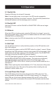
2.0 Product Description 2.1 Front Panel ON/TEST OFF REPLACE BATTERY VOLTAGE BOOST BATTERY CHARGE LOAD POWER OVERLOAD ON BATTERY VOLTAGE REDUCTION ON-LINE ON/TEST Button: Turns on the UPS to power the loads. It also activates the UPS self-test. Off Button: Turns off the UPS and the loads. Replace battery Indicator (Red LED): The LED illuminates when the UPS battery is no longer useful and must be replaced.
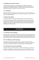
2.2 Rear Panel SITE WIRING FAULT OUTPUT SITE WIRING FAULT USB REMOTE OUT IN CIRCUIT BREAKER OUT OUTPUT REMOTE PORT FUSE INPUT INPUT M3 SCREWS (2X) SNMP PORT COVER IN S3K700 & S3K1000 S3K1600 In/Out (Telephone/Modem Connector): Provides surge suppression for telephones and modems. Output: Output power receptacles for loads. INPUT: Ac input power receptacle (line cord attached on S3K1600 models).
3.0 Pre-Installation Inspect the UPS upon receipt. Damage that may have occurred in transit is not covered under the warranty. If shipping damage is present, please contact your local carrier and SolaHD distributor immediately. Note: The packaging material is recyclable. Please reuse or dispose of it in a responsible manner. 4.0 Installation 4.1 Installation Requirements • Install the UPS in a protected area with adequate ventilation and free from excessive dust. • Do not expose the UPS to corrosive air.
4.2.4 Connect the Loads Connect the loads to the output receptacles on the rear panel of the UPS. Caution: Never connect a laser printer or plotter to the UPS with other computer equipment. Laser printers and/or plotters will require their own UPS, as they periodically experience high inrush surge currents, which may cause an overload. Note: Be careful not to overload the UPS. An audible alarm will beep continuously and the front panel OVERLOAD LED will illuminate to indicate an overload status.
5.0 Operation 5.1 Switch On Press the On button for at least 0.5 seconds. Note: If normal utility power is not present, the UPS may be engaged by depressing the ON button for at least 3 seconds. The load will be powered from the internal batteries until the discharge point is reached. 5.2 Switch Off Hold the OFF button until the ON-LINE or ON BATTERY LEDs are no longer illuminated. 5.3 Silence When the UPS is in backup mode, press the ON button for at least 1 second to silence the audible alarm.
5.6 Battery Charge Bar Graph The 5-LED display shows the present charge of the UPS’s batteries as a percentage of the batteries’ capacity. When all five LEDs are illuminated, the batteries are fully charged. When only two LEDs are illuminated, the batteries can supply less than 2 minutes of run time for the load. 5.7 Cold Start When the UPS is off and there is no utility power, you can use the cold start feature to apply power to the loads from the UPS’s batteries.
7.0 Software & Interface 7.1 Power Monitoring Software UPSMON software (or other power monitoring software) utilizes a standard RS-232 interface to perform monitoring functions and an orderly shutdown of the protected equipment in the event of power failure. UPSMON displays all the diagnostic symptoms on the monitor, including voltage, frequency and battery levels. UPSMON is available for Windows applications and other OS compatible solutions. 7.2 .NETpower Card (optional—S3K1600 models only) The .
7.4.1 Remote Port PIN Configurations PIN Description I/O 2 Power fail. Generates a high to low signal when the line fails. Notes: Normally open status; closed when active. Open collector output must be pulled up to a common referenced supply no greater than +40 V dc. The transistors are capable of a maximum non-inductive dc load of 25 mA. Use only pin 4 as the common. Output 4 Reference ground for PINs 2 & 5 5 Battery low.
9.0 Troubleshooting Problem Probable Cause Solution Problem with input power source Check the input power source Fuse blown on rear panel Replace fuse with same type and rating and check load ON/TEST button was not pressed for 1+ seconds Press the ON/TEST button for more than 2 seconds Output short circuit or overload on UPS Turn off UPS. Remove all loads to ensure there are no problems or internal short circuits. Press the ON/TEST button for more than 2 seconds.
10.0 Specifications Catalog Number Parameter Capacity S3K700 S3K1000 S3K1600 700 VA/480 W 1000 VA/750 W 1440 VA/1200 W Input Nominal Voltage 120 V ±25%, single phase Frequency 50 or 60 Hz ±5% (auto-sensing) Output Voltage (on battery) Pure sine wave output at nominal ±5% Frequency (on battery) Voltage Regulation (AVR) 50 or 60 Hz ±0.5% AVR automatically increases output voltage 15% above input voltage if -9% to -25% of nominal is detected.
Catalog Number Parameter S3K700 S3K1000 S3K1600 Backup Time at Full Load 5 min. 3.5 min. 3 min. Backup Time at Half Load 14 min. 12.5 min. 10 min. Alarms Battery Backup Slow beeping sound (about 0.25 Hz) Battery Low Rapid beeping sound (about 1.0 Hz) Overload Continuous beeping sound Interface RS-232 Interface Bidirectional communication port USB N/A USB port N/A .NETpower card (P/N: SNMPCARDPC) communication Option Card Agency approvals Safety UL1778, CAN/CSA-C22.2 No.
Technical Support U.S.: (800) 377-4384 International: (847) 268-6651 E-mail: tech@solahd.com Web site: www.solahd.