
User's Manual


Operation and Display Panel
SOLA HD
®
S5KC
™
44
4.0 OPERATION AND DISPLAY PANEL
4.1 Overview
This chapter describes the functions and operation of the UPS display panel. The LCD is composed of
an LED mimic power flow diagram, fault LED indicator and LCD screen to show detailed operational
information and UPS alarm list using the menu buttons. For location and information about the
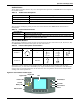
display panel, refer to Figure 51 below
Figure 51 Operation and display panel
Mimic LEDs
The mimic power flow LEDs indicate current operating state of the UPS. The state descriptions of the
LEDs are given in Table 17.
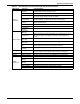
Table 17 LED descriptions
LED State Description
AC LED
On (Green) The rectifier is functioning normally
Flashing (Green) The AC mains is normal, but the rectifier is not functioning properly
On (Red) The rectifier is faulty
Off The AC mains is abnormal, and the rectifier is not functioning
Battery LED
On (Green) The battery is discharging
Flashing (Green) The battery has a pre-alarm of low voltage
On (Red) The DC-DC converter is faulty
Off The battery is charging, and the DC-DC converter is not functioning
Bypass LED
On (Green) The bypass is supplying power
On (Red) The bypass is abnormal and not available
Off The bypass is normal, but not supplying output power
Inverter LED
On (green) The inverter is supplying output power
Flashing (green)
The inverter is starting up, in soft start or phase locked, and is not supplying
output power
On (red) The inverter is faulty
Off The inverter is off
Output LED
On (green) The UPS output is supplying power
Flashing (green) The UPS internal manual bypass is supplying output power
On (red) The UPS has output overload
Off The UPS does not have output power
Fault LED
On (yellow) The UPS has an alarm or alarms
On (red) The UPS has one or more faults
Off UPS operating normally with no alarm or fault conditions
Menu Buttons
Bypass LED
Inverter LED
AC LED
Battery LED
LCD
On/Off Button
Fault LED
Alarm Silence
Button
Output LED