Reference Manual 00809-0100-4697, Rev EA October 2011 Rosemount 848T High Density Temperature Transmitter with FOUNDATION™ fieldbus Device Revision 7 www.rosemount.
Reference Manual 00809-0100-4697, Rev EA October 2011 Rosemount 848T Rosemount 848T High Density Temperature Transmitter with FOUNDATION fieldbus NOTICE Read this manual before working with the product. For personal and system safety, and for optimum product performance, make sure to thoroughly understand the contents before installing, using, or maintaining this product. The United States has two toll-free assistance numbers and one international number. Customer Central 1-800-999-9307 (7:00 a.m.
Reference Manual 00809-0100-4697, Rev EA October 2011 Rosemount 848T Table of Contents SECTION 1 Introduction Safety Messages . . . . . . . . . . . . . . . . . . . . . . . . . . . . . . . . . . . . . . . . . 1-1 Warnings . . . . . . . . . . . . . . . . . . . . . . . . . . . . . . . . . . . . . . . . . . . . 1-1 Overview . . . . . . . . . . . . . . . . . . . . . . . . . . . . . . . . . . . . . . . . . . . . . . . 1-2 Transmitter . . . . . . . . . . . . . . . . . . . . . . . . . . . . . . . . . . . . . . .
Reference Manual Rosemount 848T 00809-0100-4697, Rev EA October 2011 SECTION 4 Operation and Maintenance Safety Messages . . . . . . . . . . . . . . . . . . . . . . . . . . . . . . . . . . . . . . . . . 4-1 Warnings . . . . . . . . . . . . . . . . . . . . . . . . . . . . . . . . . . . . . . . . . . . . 4-1 Foundation fieldbus Information . . . . . . . . . . . . . . . . . . . . . . . . . . . . . 4-1 Commissioning (Addressing) . . . . . . . . . . . . . . . . . . . . . . . . . . . . .
Reference Manual 00809-0100-4697, Rev EA October 2011 Section 1 Rosemount 848T Introduction Safety Messages . . . . . . . . . . . . . . . . . . . . . . . . . . . . . . . . . page 1-1 Overview . . . . . . . . . . . . . . . . . . . . . . . . . . . . . . . . . . . . . . . page 1-2 Service Support . . . . . . . . . . . . . . . . . . . . . . . . . . . . . . . . .
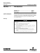
Reference Manual 00809-0100-4697, Rev EA October 2011 Rosemount 848T OVERVIEW Transmitter The Rosemount 848T is optimal for process temperature measurement because of its ability to simultaneously measure eight separate and independent temperature points with one transmitter. Multiple temperature sensor types may be connected to each 848T transmitter. In addition, the 848T can accept 4-20 mA inputs.
Reference Manual 00809-0100-4697, Rev EA October 2011 SERVICE SUPPORT Rosemount 848T To expedite the return process in North America, call the Emerson Process Management National Response Center toll-free at 800-654-7768. This center, available 24 hours a day, will assist with any needed information or materials.
Reference Manual Rosemount 848T 1-4 00809-0100-4697, Rev EA October 2011
Reference Manual 00809-0100-4697, Rev EA October 2011 Section 2 Rosemount 848T Installation Safety Messages . . . . . . . . . . . . . . . . . . . . . . . . . . . . . . . . . page 2-1 Mounting . . . . . . . . . . . . . . . . . . . . . . . . . . . . . . . . . . . . . . . page 2-1 Wiring . . . . . . . . . . . . . . . . . . . . . . . . . . . . . . . . . . . . . . . . . . page 2-4 Grounding . . . . . . . . . . . . . . . . . . . . . . . . . . . . . . . . . . . . . . page 2-8 Switches . . . . . . . . . . . . .
Reference Manual 00809-0100-4697, Rev EA October 2011 Rosemount 848T Mounting to a DIN Rail Without an Enclosure To mount the 848T to a DIN rail without an enclosure, follow these steps: 1. Pull up the DIN rail mounting clip located on the top back side of the transmitter. 2. Hinge the DIN rail into the slots on the bottom of the transmitter. 3. Tilt the 848T and place onto the DIN rail. Release the mounting clip. The transmitter should be securely fastened to the DIN rail. Figure 2-1.
Reference Manual 00809-0100-4697, Rev EA October 2011 Mounting to a 2-in. Pipe Stand Rosemount 848T Use the optional mounting bracket (option code B6) to mount the 848T to a 2-in. pipe stand when using a junction box. Aluminum/Plastic Junction Box (styles JA and JP) Front View 5.1 (130) 10.2 (260) Side View 6.6 (167) fully assembled Stainless Steel Junction Box (style JS) Front View 4.7 (119) Side View 7.
Reference Manual 00809-0100-4697, Rev EA October 2011 Rosemount 848T WIRING If the sensor is installed in a high-voltage environment and a fault condition or installation error occurs, the sensor leads and transmitter terminals could carry lethal voltages. Use extreme caution when making contact with the leads and terminals. NOTE Do not apply high voltage (e.g. AC line voltage) to the transmitter terminals. Abnormally high voltage can damage the unit (bus terminals are rated to 42.4 VDC). Figure 2-3.
Reference Manual 00809-0100-4697, Rev EA October 2011 Rosemount 848T RTD or Ohm Inputs Various RTD configurations, including 2-wire and 3-wire are used in industrial applications. If the transmitter is mounted remotely from a 3-wire RTD, it will operate within specifications, without recalibration, for lead wire resistances of up to 60 ohms per lead (equivalent to 6,000 feet of 20 AWG wire).
Reference Manual 00809-0100-4697, Rev EA October 2011 Rosemount 848T Figure 2-5. 848T Analog Input Wiring Diagram Analog Input Connectors Analog Transmitters Power Supply Figure 2-6.
Reference Manual 00809-0100-4697, Rev EA October 2011 Power Supply Rosemount 848T Connections The transmitter requires between 9 and 32 VDC to operate and provide complete functionality. The DC power supply should provide power with less than 2% ripple. A fieldbus segment requires a power conditioner to isolate the power supply filter and decouple the segment from other segments attached to the same power supply. All power to the transmitter is supplied over the signal wiring.
Reference Manual 00809-0100-4697, Rev EA October 2011 Rosemount 848T GROUNDING The 848T transmitter provides input/output isolation up to 620 V rms. NOTE Neither conductor of the fieldbus segment can be grounded. Grounding out one of the signal wires will shut down the entire fieldbus segment. Shielded Wire Each process installation has different requirements for grounding. Use the grounding options recommended by the facility for the specific sensor type or begin with grounding option 1 (most common).
Reference Manual 00809-0100-4697, Rev EA October 2011 Rosemount 848T Grounded Thermocouple Inputs 1. Ground sensor wiring shield(s) at the sensor. 2. Ensure that the sensor wiring and signal wiring shields are electrically isolated from the transmitter enclosure. 3. Do not connect the signal wiring shield to the sensor wiring shield(s). 4. Ground signal wiring shield at the power supply end. Power Supply 848T Sensor Wires Shield ground points Analog Device Inputs 1.
Reference Manual 00809-0100-4697, Rev EA October 2011 Rosemount 848T SWITCHES Figure 2-8. Switch Location on the Rosemount 848T NOT USED SECURITY SIMULATE ENABLE Security After configuring the transmitter, the data can be protected from unwarranted changes. Each 848T is equipped with a security switch that can be positioned “ON” to prevent the accidental or deliberate change of configuration data. This switch is located on the front side of the electronics module and is labeled SECURITY.
Reference Manual 00809-0100-4697, Rev EA October 2011 TAGGING Rosemount 848T Commissioning Tag The 848T has been supplied with a removable commissioning tag that contains both the Device ID (the unique code that identifies a particular device in the absence of a device tag) and a space to record the device tag (the operational identification for the device as defined by the Piping and Instrumentation Diagram (P&ID)).
Reference Manual 00809-0100-4697, Rev EA October 2011 Rosemount 848T INSTALLATION Using Cable Glands Use the following steps to install the 848T with Cable Glands: 1. Remove the junction box cover by unscrewing the four cover screws. 2. Run the sensor and power/signal wires through the appropriate cable glands using the pre-installed cable glands (see Figure 2-10). 3. Install the sensor wires into the correct screw terminals (follow the label on the electronics module). 4.
Reference Manual 00809-0100-4697, Rev EA October 2011 Section 3 Rosemount 848T Configuration Safety Messages . . . . . . . . . . . . . . . . . . . . . . . . . . . . . . . . . page 3-1 Configuration . . . . . . . . . . . . . . . . . . . . . . . . . . . . . . . . . . . page 3-2 Common Configurations for High Density Applications page 3-4 Block Configuration . . . . . . . . . . . . . . . . . . . . . . . . . . . . . .
Reference Manual 00809-0100-4697, Rev EA October 2011 Rosemount 848T CONFIGURATION Standard Each FOUNDATION fieldbus configuration tool or host system has a different way of displaying and performing configurations. Some will use Device Descriptions (DDs) and DD Methods to make configuration and displaying of data consistent across host platforms. Unless otherwise specified, the 848T will be shipped with the following configuration (default): Table 3-1.
Reference Manual 00809-0100-4697, Rev EA October 2011 Alarms Rosemount 848T Use the following steps to configure the alarms, which are located in the Resource Function Block. 1. Set the resource block to OOS. 2. Set WRITE_PRI to the appropriate alarm level (WRITE_PRI has a selectable range of priorities from 0 to 15, see “Alarm Priority Levels” on page 3-11. Set the other block alarm parameters at this time. 3.
Reference Manual 00809-0100-4697, Rev EA October 2011 Rosemount 848T COMMON CONFIGURATIONS FOR HIGH DENSITY APPLICATIONS 6. Set the Deadband from 0 to 90%. This threshold is used to clear the PV status. 7. Set Status Priority. This determines what happens when the specific limit has been exceeded. No Alert - Ignores limit settings. Advisory Sets Advisory Plant Web Alert, but does not do anything with PV status. Warning - Sets a Maintenance Plant Web Alert and sets PV status to uncertain.
Reference Manual 00809-0100-4697, Rev EA October 2011 Rosemount 848T Monitoring Application with a Single Selection Example: Average exhaust temperature of gas and turbine where there is a single alarm level for all inputs. IN_1 Out Out_2 IN_2 Out_D Out_3 IN_3 Out_4 IN_4 Out_5 IN_5 Out_6 IN_6 Out_7 IN_7 Out_8 IN_8 Out_1 MAI Function Block ISEL Function Block 1. Link the MAI outputs to the ISEL inputs. 2. Place the Multiple Analog Input (MAI) function block in OOS mode (set MODE_BLK.
Reference Manual 00809-0100-4697, Rev EA October 2011 Rosemount 848T Interfacing Analog Transmitters to FOUNDATION fieldbus Transducer Block Configuration Use the sensor configuration method to set the sensor type to mV – 2-wire for the applicable transducer block or follow these steps. 1. Set the MODE_BLK.TARGET to OOS mode, or set the SENSOR_MODE to configuration. 2. Set the SENSOR to mV. 3. Set the MODE_BLK.TARGET to AUTO, or set the SENSOR_MODE to operation.
Reference Manual 00809-0100-4697, Rev EA October 2011 Rosemount 848T BLOCK CONFIGURATION Resource Block The resource block defines the physical resources of the device including type of measurement, memory, etc. The resource block also defines functionality, such as shed times, that is common across multiple blocks. The block has no linkable inputs or outputs and it performs memory-level diagnostics. Table 3-2.
Reference Manual 00809-0100-4697, Rev EA October 2011 Rosemount 848T Table 3-2.
Reference Manual 00809-0100-4697, Rev EA October 2011 Rosemount 848T Table 3-2.
Reference Manual 00809-0100-4697, Rev EA October 2011 Rosemount 848T Table 3-2. Resource Block Parameters Number Parameter 83 ADVISE_ALM 84 HEALTH_INDEX 85 PWA_SIMULATE Description Alarm indicating advisory alarms. These conditions do not have a direct impact on the process or device integrity. Parameter representing the overall health of the device, 100 being perfect and 1 being non-functioning.
Reference Manual 00809-0100-4697, Rev EA October 2011 Rosemount 848T Out of Service (OOS) The block is not processing its tasks. When the resource block is in OOS, all blocks within the resource (device) are forced into OOS. The BLOCK_ERR parameter shows Out of Service. In this mode, changes can be made to all configurable parameters. The target mode of a block may be restricted to one or more of the supported modes.
Reference Manual 00809-0100-4697, Rev EA October 2011 Rosemount 848T Table 3-5. Failure Alarms Alarm Priority Electronics Failure 1 Memory Failure 2 Hardware/Software Incompatible 3 Body Temperature Failure 4 Sensor 8 Failure 5 Sensor 7 Failure 6 Sensor 6 Failure 7 Sensor 5 Failure 7 Sensor 4 Failure 9 Sensor 3 Failure 10 Sensor 2 Failure 11 Sensor 1 Failure 12 FAILED_MASK This parameter will mask any of the failed conditions listed in FAILED_ENABLED.
Reference Manual 00809-0100-4697, Rev EA October 2011 Table 3-6. Maintenance Alarms/Priority Alarm Rosemount 848T Alarm Priority Sensor 8 Degraded 1 Sensor 7 Degraded 2 Sensor 6 Degraded 3 Sensor 5 Degraded 4 Sensor 4 Degraded 5 Sensor 3 Degraded 6 Sensor 2 Degraded 7 Sensor 1 Degraded 8 Body Temperature Out of Range 9 CJC Degraded 10 MAINT_MASK The MAINT_MASK parameter will mask any of the failed conditions listed in MAINT_ENABLED.
Reference Manual 00809-0100-4697, Rev EA October 2011 Rosemount 848T ADVISE_MASK The ADVISE_MASK parameter will mask any of the failed conditions listed in ADVISE_ENABLED. A bit on means the condition is masked out from alarming and will not be reported. ADVISE_PRI ADVISE_PRI designates the alarming priority of the ADVISE_ALM, see Table 3-4 on page 3-11. The default is 0 and the recommended values are 1 or 2. ADVISE_ACTIVE The ADVISE_ACTIVE parameter displays which of the advisories is active.
Reference Manual 00809-0100-4697, Rev EA October 2011 Rosemount 848T Alarm Type Active Event Maintenance Sensor 8 Degraded Failed Sensor 1 Failure Failed Sensor 2 Failure Failed Sensor 3 Failure Failed Sensor 4 Failure Failed Sensor 5 Failure Failed Sensor 6 Failure Failed Sensor 7 Failure Failed Sensor 8 Failure Failed Body Temperature Failure Hardware/Software Incompatible Failed Failed Memory Error Failed Electronics Failure Recommended Action Confirm the operating range of Se
Reference Manual 00809-0100-4697, Rev EA October 2011 Rosemount 848T Transducer Block Channel Definitions The 848T supports multiple sensor inputs. Each input has a channel assigned to it allowing an AI or MAI Function Blocks to be linked to that input. The channels for the 848T are as follows: Table 3-8.
Reference Manual 00809-0100-4697, Rev EA October 2011 Rosemount 848T BLOCK_ERR Table 3-9. Block/Transducer Error Condition Number, Name, and Description 0 7 15 Other(1) Input failure/process variable has bad status Out of service: The actual mode is out of service (1) If BLOCK_ERR is “other,” then see XD_ERROR. Transducer Block Modes The transducer block supports two modes of operation as defined by the MODE_BLK parameter: Automatic (Auto) The block outputs reflect the analog input measurement.
Reference Manual 00809-0100-4697, Rev EA October 2011 Rosemount 848T Table 3-10.
Reference Manual 00809-0100-4697, Rev EA October 2011 Rosemount 848T Table 3-10.
Reference Manual 00809-0100-4697, Rev EA October 2011 Rosemount 848T Transducer Block Sub-Parameter Tables Table 3-11. XD_ERROR Sub-Parameter Structure XD ERROR 0 20 Electronics Failure An error has occurred that could not be classified as one of the errors listed below. An error occurred during calibration of the device or a calibration error has been detected during operation of the device.
Reference Manual 00809-0100-4697, Rev EA October 2011 Table 3-13. SENSOR_STATUS Sub-Parameter Structure Table 3-14.
Reference Manual 00809-0100-4697, Rev EA October 2011 Rosemount 848T Table 3-17. DUAL_SENSOR CONFIG Sub-Parameter Structure DUAL SENSOR CONFIG STRUCTURE Parameter Description DUAL_SENSOR_MODE DUAL_SENSOR_TAG Sensor to be used in DUAL_SENSOR_CALC INPUT_B Sensor to be used in DUAL_SENSOR_CALC ENG_UNITS Table 3-19.
Reference Manual 00809-0100-4697, Rev EA October 2011 Table 3-20. Validation Config Sub-Parameter Structure Rosemount 848T Validation Value Sub-Parameter Structure Parameter VALIDATION_MODE Description Activates the measurement validation data gathering process 0 = Disable 1 = Enable SAMPLE_RATE Number of seconds per sample used for measurement validation data collection. This shouldn't exceed 10 seconds per sample, but currently there are no upper limits.
Reference Manual 00809-0100-4697, Rev EA October 2011 Rosemount 848T 3-24 1. Under SENSOR_CALIB, the SENSOR_NUMBER to the number of the sensor to calibrate. 2. Set CALIB_UNIT to calibration unit. 3. Set CALIB_METHOD to User Trim (seeTable 3-8 on page 3-16 for valid values). 4. Set the input value of the sensor simulator to be within the range defined by CALIB_LO_LIMIT and CALIB_HI_LIMIT. 5. Set CALIB_POINT_LO (CALIB_POINT_HI) to the value set at the sensor simulator. 6.
Reference Manual 00809-0100-4697, Rev EA October 2011 Section 4 Rosemount 848T Operation and Maintenance Safety Messages . . . . . . . . . . . . . . . . . . . . . . . . . . . . . . . . . page 4-1 Foundation fieldbus Information . . . . . . . . . . . . . . . . . . . . page 4-1 Hardware Maintenance . . . . . . . . . . . . . . . . . . . . . . . . . . . . page 4-3 Troubleshooting . . . . . . . . . . . . . . . . . . . . . . . . . . . . . . . . .
Reference Manual 00809-0100-4697, Rev EA October 2011 Rosemount 848T Table 4-1. Block Diagram for the Rosemount 848T Function Blocks • AI, MAI, and ISEL FOUNDATION Fieldbus Communications Stack Analog-to-Digital Signal Conversion (8 sensors) Resource Block • physical device information Transducer Block Measurement Sensor • sensor and differential temp • terminal temp.
Reference Manual 00809-0100-4697, Rev EA October 2011 Rosemount 848T HARDWARE MAINTENANCE The 848T has no moving parts and requires a minimal amount of scheduled maintenance. If a malfunction is suspected, check for an external cause before performing the diagnostics presented below. Sensor Check To determine whether the sensor is causing the malfunction, connect a sensor calibrator or simulator locally at the transmitter.
Reference Manual 00809-0100-4697, Rev EA October 2011 Rosemount 848T TROUBLESHOOTING FOUNDATION fieldbus Symptom Possible Cause Corrective Action Device does not show up in the live list Network configuration parameters are incorrect Set the network parameters of the LAS (host system) according to the FF Communications Profile ST: 8 MRD: 4 DLPDU PhLO: 4 MID: 7 TSC: 4 (1 ms) T1: 96000 (3 seconds) T2: 9600000 (300 seconds) T3: 480000 (15 seconds) Set first Unpolled Node and Number of UnPolled Nodes so t
Reference Manual 00809-0100-4697, Rev EA October 2011 Appendix A Rosemount 848T Reference Data Functional Specifications . . . . . . . . . . . . . . . . . . . . . . . . . page A-1 Physical Specifications . . . . . . . . . . . . . . . . . . . . . . . . . . . page A-3 Performance Specifications . . . . . . . . . . . . . . . . . . . . . . . page A-4 Function Blocks . . . . . . . . . . . . . . . . . . . . . . . . . . . . . . . . . page A-4 Dimensional Drawings . . . . . . . . . . . . . . . . . . . . . . . .
Reference Manual 00809-0100-4697, Rev EA October 2011 Rosemount 848T Transient Protection The transient protector (option code T1) helps to prevent damage to the transmitter from transients induced on the loop wiring by lightning, welding, heavy electrical equipment, or switch gears. This option is installed at the factory for the Rosemount 848T and is not intended for field installation. Update Time Approximately 1.5 seconds to read all 8 inputs.
Reference Manual 00809-0100-4697, Rev EA October 2011 Rosemount 848T PHYSICAL SPECIFICATIONS Mounting The Rosemount 848T can be mounted directly onto a DIN rail or it can be ordered with an optional junction box. When using the optional junction box, the transmitter can be mounted onto a panel or a 2-in. pipe stand (with option code B6). Entries for Optional Junction Box No entry • Used for custom fittings Cable Gland • 9 x M20 nickel-plated brass glands for 7.5–11.
Reference Manual 00809-0100-4697, Rev EA October 2011 Rosemount 848T FUNCTION BLOCKS Analog Input (AI) • Processes the measurement and makes it available on the fieldbus segment. • Allows filtering, alarming, and engineering unit changes. Input Selector (ISEL) • Used to select between inputs and generate an output using specific selection strategies such as minimum, maximum, midpoint, or average temperature.
Reference Manual 00809-0100-4697, Rev EA October 2011 Rosemount 848T Accuracy Table 1. Input Options/Accuracy Input Ranges Sensor Option Sensor Reference 2- and 3-Wire RTDs Pt 50 ( = 0.00391) GOST 6651-94 Pt 100 ( = 0.00391) GOST 6651-94 Pt 100 ( = 0.00385) IEC 751; = 0.00385, 1995 Pt 100 ( = 0.003916) JIS 1604, 1981 Pt 200 ( = 0.00385) IEC 751; = 0.00385, 1995 Pt 200 ( = 0.003916) JIS 1604; = 0.003916, 1981 Pt 500 IEC 751; = 0.00385, 1995 Pt 1000 IEC 751; = 0.
Reference Manual 00809-0100-4697, Rev EA October 2011 Rosemount 848T Analog Sensors 4–20mA Two types of 4–20 mA sensors are compatible with the Rosemount 848T. These types must be ordered with the S002 option code complete with an analog connector kit. The alarm levels, accuracy for each type are listed in Table 2. Table 2. Analog Sensors Sensor Option Alarm Levels Accuracy 4–20mA (Rosemount Standard) 4–20mA (NAMUR) 3.9 to 20.8 mA ± 0.01mA 3.8 to 20.5 mA ± 0.
Reference Manual 00809-0100-4697, Rev EA October 2011 Rosemount 848T Ambient Temperature Effect Transmitter may be installed in locations where the ambient temperature is between -40 and 85 °C (-40 and 185 °F) Table 3. Ambient Temperature Effects NIST Type Accuracy per 1.0 °C (1.8 °F) Change in Ambient Temperature(1)C Temperature Range (°C) RTD Pt 50 ( = 0.00391) • 0.004 °C (0.0072 °F) NA Pt 100 ( = 0.00391) • 0.002 °C (0.0036 °F) NA Pt 100 ( = 0.00385) • 0.003 °C (0.
Reference Manual 00809-0100-4697, Rev EA October 2011 Rosemount 848T Ambient Temperature Notes Examples: When using a Pt 100 ( = 0.00385) sensor input at 30 °C ambient temperature: • Digital Temperature Effects: 0.003 °C x (30 - 20) = .03 °C • Worst Case Error: Digital + Digital Temperature Effects = 0.3 °C + .03 °C = .33 °C • Total Probable Error 0.30 2 + 0.03 2 = 0.
Reference Manual 00809-0100-4697, Rev EA October 2011 Rosemount 848T Aluminum/Plastic Junction Box—Cable Gland (option codes JA2 and JP2) Top View 3-D View 10.24 (260) Ground Screw Side View Front View 7.84 (199.2) 2.44 (62) 1.57 (40) 6.30 (160) 4.41 (112) 1.73 (44) 2.28 (58) 3.78 (96) 1.10 (28) Dimensions are in inches (millimeters) Stainless Steel Junction Box—Cable Gland (option code JS2) Top View 3-D View 9.91 (231) 7.7 (196) Ground Screw Side View Front View 9.14 (232.2) 1.8 (46) 1.
Reference Manual 00809-0100-4697, Rev EA October 2011 Rosemount 848T Aluminum/Plastic Junction Box—Conduit Entry (option codes JA3 and JP3) Top View 3-D View 10.2 (260) Front View Side View 157 (40) 2.44 (62) 10.2 (260) 3.5 (89) 1.7 (42) Five Plugged 0.86-in. diameter holes suitable for installing 1/2-in. NPT fittings Dimensions are in inches (millimeters) Stainless Steel Junction Box—Conduit Entry (option code JS3) Top View 3-D View 9.1 (231) 7.7 (196) Ground Screw Front View Side View 1.
Reference Manual 00809-0100-4697, Rev EA October 2011 Rosemount 848T Mounting Options Aluminum/Plastic Junction Box (styles JA and JP) Front View 5.1 (130) 10.2 (260) Side View Stainless Steel Junction Box (style JS) Front View Side View 4.5 (114) 6.6 (167) fully assembled 7.
Reference Manual Rosemount 848T 00809-0100-4697, Rev EA October 2011 ORDERING INFORMATION Table A-1. Rosemount 848T FOUNDATION fieldbus Ordering Information ★ The Standard offering represents the most common options. The starred options (★) should be selected for best delivery. __The Expanded offering is subject to additional delivery lead time.
Reference Manual 00809-0100-4697, Rev EA October 2011 Rosemount 848T Table A-1. Rosemount 848T FOUNDATION fieldbus Ordering Information ★ The Standard offering represents the most common options. The starred options (★) should be selected for best delivery. __The Expanded offering is subject to additional delivery lead time. Enclosure Options Standard Standard JP1 Plastic Junction Box; No Entries ★ JP2 Plastic Box, Cable Glands (9 x M20 nickel-plated brass glands for 7.5–11.
Reference Manual Rosemount 848T A-14 00809-0100-4697, Rev EA October 2011
Reference Manual 00809-0100-4697, Rev EA October 2011 Appendix B Rosemount 848T Product Certificates Hazardous Locations Certificates . . . . . . . . . . . . . . . . . . . page B-1 Intrinsically Safe and Non-Incendive Installations . . . . . page B-11 Installation Drawings . . . . . . . . . . . . . . . . . . . . . . . . . . . . .
Reference Manual 00809-0100-4697, Rev EA October 2011 Rosemount 848T IE FISCO (Fieldbus Intrinsically Safe Concept) Intrinsic Safety Intrinsically safe for use in Class I, Division 1, Groups A, B, C, D; when installed in accordance with Rosemount Drawing 00848-4404. Temperature Code: T4 (Tamb = –40 to 60 °C) Non-incendive for use in Class I, Division 2, Groups A, B, C, D (suitable for use with non-incendive field wiring); when installed in accordance with Rosemount Drawing 00848-4404.
Reference Manual 00809-0100-4697, Rev EA October 2011 Rosemount 848T Canadian Standards Association (CSA) Certifications E6 Explosion-Proof and Dust Ignition-Proof Class I, Division 1, Groups B, C, and D. Class II, Division 1, Groups E, F, and G. Class III Must be installed in enclosure option JX3. Install per drawing 00848-1041. Conduit seal not required. Suitable for use in Class I, Division 2, Groups A, B, C, D. when installed per Rosemount drawing 00848-4405.
Reference Manual 00809-0100-4697, Rev EA October 2011 Rosemount 848T N6 Class I, Division 2 Suitable for use in Class I, Division 2, Groups A, B, C, D. when installed per Rosemount drawing 00848-4405. Temperature Code: T3C = (–50 Ta 60 °C) Must be installed in a suitable enclosure as determined acceptable by the local inspection authority.
Reference Manual 00809-0100-4697, Rev EA October 2011 Rosemount 848T Special Conditions for Safe Use (x): 1. This apparatus must be installed in an enclosure which affords it a degree of protection of at least IP20. Non-metallic enclosures must have a surface resistance of less than 1Gohm. Light alloy or zirconium enclosures must be protected from impact and friction when installed. 2. The apparatus will not meet the 500V rms isolation test required by Clause 6.4.12 on EN 60079-11:2007.
Reference Manual 00809-0100-4697, Rev EA October 2011 Rosemount 848T Special Conditions for Safe Use (x): 1. Provisions shall be made, external to the apparatus, to prevent the rated voltage of the apparatus supply is not exceeded by transient disturbances of more than 40% 2. The electrical circuit is connected directly to earth; this must be taken into account when installing the apparatus.
Reference Manual 00809-0100-4697, Rev EA October 2011 Rosemount 848T Special Conditions of Safe Use (x): 1. The component must be housed in a suitable certified enclosure. 2. Provisions shall be made, external to the apparatus, to prevent the rated voltage (42.2 V dc) being exceeded by transient disturbances of more than 40%. IECEx Certifications I7 IECEx Intrinsic Safety Certificate No.: IECExBAS09.0030X Ex ia IIC T4 (Tamb = –50 to 60 °C) Table B-12.
Reference Manual 00809-0100-4697, Rev EA October 2011 Rosemount 848T N7 IECEx Type n Approval Certificate No.” IECExBAS09.0032X Ex Na nL IIC T5 (Tamb = – 40 to 65 °C) NOTE: N7 is valid with S001 and S002 Input Types Table B-14. IECEx Approved Entity Parameters Power/Bus Ui = 42.4 Vdc Ci = 0 Li = 0 Sensor Uo = 5 Vdc Io = 2.5 mA Co = 1000 F Lo = 1000 mH Special Conditions of Safe Use: 1.
Reference Manual 00809-0100-4697, Rev EA October 2011 Rosemount 848T China (NEPSI)Certifications I3 Intrinsic Safety Ex ia IIC T4 Certification Number: GYJ111365X Special Conditions for Safe Use (x): 2.1. Only when temperature transmitter is installed in IP 20(GB4208-2008) housing, it could be used in hazardous location. The metallic housing should observe the requirements of GB3836.1-2000 Clause 8. The non-metallic housing should observe the requirements of GB3836.1-2000 Clause 7.3.
Reference Manual 00809-0100-4697, Rev EA October 2011 Rosemount 848T 2.7. End users are not permitted to change any component’s insides, but to settle the problem, in conjunction with manufacturer to avoid damage to the product. 2.8. During installation, use and maintenance of this product, observe following standards: GB3836.13-1997 "Electrical apparatus for explosive gas atmospheres Part 13: Repair and overhaul for apparatus used in explosive gas atmospheres." GB3836.
Reference Manual 00809-0100-4697, Rev EA October 2011 Rosemount 848T INTRINSICALLY SAFE AND NON-INCENDIVE INSTALLATIONS Zone 2 (category 3) Approval Safe Area Division 2 Zone 1 (category 2) Zone 0 (category 1) Division 1 GAS INSTALLATIONS I5, I6, I1, I7, IE, IA Approved I.S.
Reference Manual Rosemount 848T INSTALLATION DRAWINGS 00809-0100-4697, Rev EA October 2011 The installation guidelines presented by the drawings must be followed in order to maintain certified ratings for installed transmitters.
Reference Manual 00809-0100-4697, Rev EA October 2011 Rosemount 848T Electronic Master – PRINTED COPIES ARE UNCONTROLLED – Rosemount Proprietary Figure B-1.
Electronic Master – PRINTED COPIES ARE UNCONTROLLED – Rosemount Proprietary Reference Manual Rosemount 848T B-14 00809-0100-4697, Rev EA October 2011
00809-0100-4697, Rev EA October 2011 Electronic Master – PRINTED COPIES ARE UNCONTROLLED – Rosemount Proprietary Reference Manual Rosemount 848T B-15
Reference Manual Rosemount 848T 00809-0100-4697, Rev EA October 2011 Electronic Master – PRINTED COPIES ARE UNCONTROLLED – Rosemount Proprietary Figure B-2.
00809-0100-4697, Rev EA October 2011 Electronic Master – PRINTED COPIES ARE UNCONTROLLED – Rosemount Proprietary Reference Manual Rosemount 848T B-17
Electronic Master – PRINTED COPIES ARE UNCONTROLLED – Rosemount Proprietary Reference Manual Rosemount 848T B-18 00809-0100-4697, Rev EA October 2011
Reference Manual 00809-0100-4697, Rev EA October 2011 Appendix C Rosemount 848T FOUNDATION™ fieldbus Technology Overview . . . . . . . . . . . . . . . . . . . . . . . . . . . . . . . . . . . . . . . page C-1 Function Blocks . . . . . . . . . . . . . . . . . . . . . . . . . . . . . . . . . page C-1 Device Descriptions . . . . . . . . . . . . . . . . . . . . . . . . . . . . . . page C-3 Block Operation . . . . . . . . . . . . . . . . . . . . . . . . . . . . . . . . . page C-3 Network Communication . . . .
Reference Manual 00809-0100-4697, Rev EA October 2011 Rosemount 848T The Fieldbus FOUNDATION has established the function blocks by defining a small set of parameters used in all function blocks called universal parameters. The FOUNDATION has also defined a standard set of function block classes, such as input, output, control, and calculation blocks. Each of these classes has a small set of parameters established for it.
Reference Manual 00809-0100-4697, Rev EA October 2011 DEVICE DESCRIPTIONS Rosemount 848T Device Descriptions (DD) are specified tool definitions that are associated with the Resource and Transducer Blocks. Device descriptions provide the definition and description of the function blocks and their parameters. To promote consistency of definition and understanding, descriptive information, such as data type and length, is maintained in the device description.
Reference Manual 00809-0100-4697, Rev EA October 2011 Rosemount 848T Two types of alerts are defined for the block: events and alarms. Events are used to report a status change when a block leaves a particular state, such as when a parameter crosses a threshold. Alarms not only report a status change when a block leaves a particular state, but also report when it returns back to that state. NETWORK COMMUNICATION Figure C-2 illustrates a simple fieldbus network consisting of a single segment (link).
Reference Manual 00809-0100-4697, Rev EA October 2011 Rosemount 848T There may be many LM devices on a segment but only the LAS is actively controlling communication traffic. The remaining LM devices on the segment are in a stand-by state, ready to take over if the primary LAS fails. This is achieved by constantly monitoring the communication traffic on the bus and determining if activity is not present.
Reference Manual 00809-0100-4697, Rev EA October 2011 Rosemount 848T Backup LAS A LM device is one that has the ability to control the communications on the bus. The LAS is the LM capable device that is currently in control of the bus. While there can be many LM devices acting as backups, there can only be one LAS. The LAS is typically a host system but for stand-alone applications, a device may be providing the role of primary LAS.
Reference Manual 00809-0100-4697, Rev EA October 2011 Rosemount 848T Figure C-4 diagrams the method of scheduled data transfer. Scheduled data transfers are typically used for the regular cyclic transfer of process loop data between devices on the fieldbus. Scheduled transfers use publisher/ subscriber type of reporting for data transfer. The LAS maintains a list of transmit times for all publishers in all devices that need to be cyclically transmitted.
Reference Manual 00809-0100-4697, Rev EA October 2011 Rosemount 848T Function Block Scheduling Figure C-6 shows an example of a link schedule. A single iteration of the link-wide schedule is called the macrocycle. When the system is configured and the function blocks are linked, a master link-wide schedule is created for the LAS. Each device maintains its portion of the link-wide schedule, known as the Function Block Schedule.
Reference Manual 00809-0100-4697, Rev EA October 2011 Rosemount 848T Appendix D Function Blocks Analog Input (AI) Function Block . . . . . . . . . . . . . . . . . . . page D-1 Multiple Analog Input (MAI) Function Block . . . . . . . . . . page D-9 Input Selector Function Block . . . . . . . . . . . . . . . . . . . . . . page D-15 ANALOG INPUT (AI) FUNCTION BLOCK The Analog Input (AI) function block processes field device measurements and makes them available to other function blocks.
Reference Manual 00809-0100-4697, Rev EA October 2011 Rosemount 848T Table D-1.
Reference Manual 00809-0100-4697, Rev EA October 2011 Rosemount 848T Table D-1. Analog Input Function Block Parameters Number Parameter Units Description 36 LO_LO_ALM None 37 38 OUT_D ALM_SEL None None 39 40 STDDEV CAP_STDDEV % of OUT Range % of OUT Range Functionality The LO LO alarm data, which includes a value of the alarm, a timestamp of occurrence and the state of the alarm. Discrete output to indicate a selected alarm condition.
Reference Manual 00809-0100-4697, Rev EA October 2011 Rosemount 848T Figure D-2. Analog Input Function Block Schematic Analog Measurement ALM_SEL Access Analog Meas. HI_HI_LIM HI_LIM LO_LO_LIM LO_LIM CHANNEL Alarm Detection OUT_D ALARM_HYS LOW_CUT OUT Cutoff Convert Filter PV Status Calc.
Reference Manual 00809-0100-4697, Rev EA October 2011 Rosemount 848T Indirect Square Root Indirect Square Root signal conversion takes the square root of the value computed with the indirect signal conversion and scales it to the range and units of the PV and OUT parameters.
Reference Manual 00809-0100-4697, Rev EA October 2011 Rosemount 848T Modes The AI Function Block supports three modes of operation as defined by the MODE_BLK parameter: Manual (Man) The value of the block output (OUT) may be set manually Automatic (Auto) OUT reflects the analog input measurement or the simulated value when simulation is enabled. Out of Service (OOS) The block is not processed. FIELD_VAL and PV are not updated and the OUT status is set to Bad: Out of Service.
Reference Manual 00809-0100-4697, Rev EA October 2011 Rosemount 848T Status Handling Normally, the status of the PV reflects the status of the measurement value, the operating condition of the I/O card, and any active alarm condition. In Auto mode, OUT reflects the value and status quality of the PV. In Man mode, the OUT status constant limit is set to indicate that the value is a constant and the OUT status is Good.
Reference Manual 00809-0100-4697, Rev EA October 2011 Rosemount 848T Application Information The configuration of the AI function block and its associated output channels depends on the specific application. A typical configuration for the AI block involves the following parameters: CHANNEL The device supports more than one measurement, so verify that the selected channel contains the appropriate measurement or derived value. Refer to Table 3-5 on page 3-11 for a listing of available channels on the 848T.
Reference Manual 00809-0100-4697, Rev EA October 2011 Rosemount 848T MULTIPLE ANALOG INPUT (MAI) FUNCTION BLOCK OUT_1 OUT_2 MAI OUT_3 The Multiple Analog Input (MAI) function block has the ability to process up to eight field device measurements and make them available to other function blocks. The output values from the MAI block are in engineering units and contain a status indicating the quality of the measurement.
Reference Manual 00809-0100-4697, Rev EA October 2011 Rosemount 848T Table D-4.
Reference Manual 00809-0100-4697, Rev EA October 2011 Rosemount 848T Figure D-3. Multiple Analog Input Function Block Timing Diagram OUT (mode in man) OUT (mode in auto) PV 63% of Change FIELD_VAL Time (seconds) PV_FTIME Figure D-4.
Reference Manual 00809-0100-4697, Rev EA October 2011 Rosemount 848T Indirect Indirect signal conversion converts the signal linearly to the accessed channel input value (or the simulated value when simulation is enabled) from its specified range (XD_SCALE) to the range and units of the PV and OUT parameters (OUT_SCALE).
Reference Manual 00809-0100-4697, Rev EA October 2011 Rosemount 848T Modes The MAI Function Block supports three modes of operation as defined by the MODE_BLK parameter: Manual (Man) The block output (OUT) may be set manually Automatic (Auto) OUT_1 to OUT_8 reflects the analog input measurement or the simulated value when simulation is enabled. Out of Service (OOS) The block is not processed. PV is not updated and the OUT status is set to Bad: Out of Service. The BLOCK_ERR parameter shows Out of Service.
Reference Manual 00809-0100-4697, Rev EA October 2011 Rosemount 848T Application Information The intended use for this type of function block is for applications where the sensor types and functionality of each channel (i.e. the simulate, scaling, filtering, alarms type, and options) are the same. The configuration of the MAI function block and its associated output channels depends on the specific application.
Reference Manual 00809-0100-4697, Rev EA October 2011 Rosemount 848T INPUT SELECTOR FUNCTION BLOCK IN_1 IN_2 IN_3 IN_4 IN_5 IN_6 IN_7 IN_8 DISABLE_1 DISABLE_2 DISABLE_3 DISABLE_4 DISABLE_5 DISABLE_6 DISABLE_7 DISABLE_8 OP_SELECT The Input Selector (ISEL) function block can be used to select the first good, Hot Backup, maximum, minimum, or average of as many as eight input values and place it at the output. The block supports signal status propagation.
Reference Manual 00809-0100-4697, Rev EA October 2011 Rosemount 848T Table D-6. Input Selector Function Block Parameters Number Parameter Units Description 15, 16, 17, 18, 29, 30, 31, 32 19 DISABLE_(1, 2, 3, 4, 5, 6, 7, 8) None A connection from another block that disables the associated input from the selection.
Reference Manual 00809-0100-4697, Rev EA October 2011 Rosemount 848T Functionality Figure D-5. Input Selector Function Block Schematic IN_n OUT Mode Logic SELECTED OP_SELECT OUT_D SELECT_TYPE MIN_GOOD STATUS_OPTS Selection Logic Alarm DISABLE_n Block Errors Table D-7 lists conditions reported in the BLOCK_ERR parameter. Conditions in bold are inactive for the ISEL block and are given for reference. Table D-7.
Reference Manual 00809-0100-4697, Rev EA October 2011 Rosemount 848T Modes The ISEL function block supports three modes of operation as defined by the MODE_BLK parameter: Manual (Man) The block output (OUT) may be set manually. Automatic (Auto) OUT reflects the selected value. Out of Service (OOS) The block is not processed. The BLOCK_ERR parameter shows Out of Service. The target mode of a block may be restricted to one or more of the supported modes.
Reference Manual 00809-0100-4697, Rev EA October 2011 Rosemount 848T Block Execution The ISEL function block reads the values and status of up to eight inputs. To specify which of the six available methods (algorithms) is used to select the output, configure the selector type parameter (SELECT_TYPE) as follows: • Max selects the maximum value of the inputs. • Min selects the minimum value of the inputs. • Avg calculates the average value of the inputs. • Mid calculates the update for eight sensors.
Reference Manual 00809-0100-4697, Rev EA October 2011 Rosemount 848T Figure D-6. Input Selector Function Block Application Example (SEL_TYPE = max) IN2 = 118 °F Input Selector (ISEL) Function Block IN3 = 104 °F IN4 = 107 °F OUT = 140 °F IN5 = 112 °F IN6 = 115 °F IN7 = 130 °F IN8 = 140 °F SEL_TYPE = max IN1 = 126 °F Figure D-7.
Reference Manual 00809-0100-4697, Rev EA October 2011 Rosemount 848T Index Numerics 2-Inch Pipe Stand Mounting . . . . . . . . . . . . .2-3 A Alarms Configuration . . . . . . . Analog Input Configuration . . . . . . . Ground . . . . . . . . . . . Analog Input Function Block Advanced Features . . Alarm Detection . . . . . Application Information Block Errors . . . . . . . . Configuration . . . . . . . Direct . . . . . . . . . . . . Filtering . . . . . . . . . . . Functionality . . . . . . . Indirect . . .
Reference Manual 00809-0100-4697, Rev EA October 2011 Rosemount 848T Modes . . . . . . . . . . . . Automatic . . . . . . . Manual . . . . . . . . Out of Service . . . . Parameters . . . . . . . . . Status Handling . . . . . . Troubleshooting . . . . . Installation . . . . . . . . . . . . . Intrinsically Safe . . . . . Non-Incendive . . . . . . . Using Cable Glands . . . Using Conduit Entries . . D-18 . D-18 . D-18 . D-18 . D-15 . D-19 . D-20 . 2-12 . . B-9 . . B-9 . 2-12 . 2-12 Modes . . . . . . . . . .
Reference Manual 00809-0100-4697, Rev EA October 2011 Standard Terms and Conditions of Sale can be found at www.rosemount.com/terms_of_sale The Emerson logo is a trademark and service mark of Emerson Electric Co. Rosemount and the Rosemount logotype are registered trademarks of Rosemount Inc. SuperModule and Coplanar are trademarks of Rosemount Inc. PlantWeb is a mark of one of the Emerson Process Management companies. HART is a registered trademark of the HART Communications Foundation.