SMMC-3 MANUAL
TABLE OF CONTE NTS GENERAL INFORMATION ...........................................................................................................3 Pre-Programmed Configuration ............................................................................................................................ 3 WARNINGS ....................................................................................................................................4 INSTALLATION ...................................................
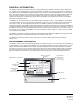
GENERAL INFORMATION The SMMC-3 Control Panel manages snow and ice melting equipment for sidewalks, driveways, gutters, downspouts, etc. Suitable for controlling all types of heating cable systems, the SMMC-3 can monitor snow and ice accumulation in three separate zones. The SMMC-3 programming allows each zone to be controlled independently or on a priority mode basis.
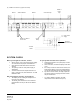
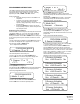
C-3 Installation & Operating Instructions Fig.2 Sample Application Illustration power contactors(s) SMMC-3 snow/ice sensor options power contactors(s) maximum 2 sensors per zone power contactors(s) * 120 VAC, to contactor coils * maximum 1 SMPS-1 sensor per zone 12 0 VAC, 450 VA WARNINGS 1. 2. 3. 4. 5. A qualified electrician must install the SMMC-3.
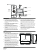
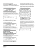
. The SMMC-3 terminal blocks serve 5 distinct connection sectors (see Fig 4), they are: 1. SMTS-1 – temperature sensor. 2. SMAS-1 aerial sensors / SMGS-1 gutter sensors (one each per zone). 3. SMPS-1 in-ground sensors (one each per zone). 4. Output to power contactors (one each per zone). 5. Control power input. Connection to each sensor is described below: 6. The SMTS-1 is connected to the left-most terminal block, identified as TEMP. SENSOR.
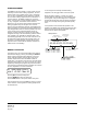
Fig. 4 SMMC-3 Control Panel (Typical Connections) SMTS-1 SMAS-1/SMGS-1 SMPS-1 Contactor Output SMMC-3 Power Input L1 L2 SMAS-1 or SMGS-1 Sensor W ire Heater Power Supply Control W iring Contactor/ Connection Box To Heater Cables SYSTEM CHECK Before you energize the controller, confirm: · All the sensors, relay coils and the power supply are connected to the proper terminal blocks. · Only approved cable was used to extend the sensors. · The polarity of the 120 VAC power supply is appropriate.
OPERATION The SMMC-3 is a programmable controller, capable of controlling three separate snow/ice melting zones. A control relay for each zone is included in the SMMC-3 to operate a contactor for each zone to energize the snow/ice melting equipment. There are two operating mode selections possible with the SMMC-3: MODE 1 – INDEPENDENT In this mode each snow/ice melting zone is controlled independently. Mode 1 allows all 3 zones to be energized simultaneously.
ZONE ASSIGNMENT To de-energize the manually activated heating equipment, use the toggle switch on the front panel. The SMMC-3 uses the concept of a zone system to most efficiently control snow/ice melting equipment. The term “zone” means an area (either surface area or roof/gutter area, or some combination of both) heated by a specific set of snow/ice melting equipment that is controlled in a common manner.
PROGRAMMING INSTRUCTIONS 2.Mode: 1 or 2 The SMMC-3 program has been structured into 6 levels; within each of these levels are further degrees of selection. Each programming step is clearly described on the LCD, and easily adjusted by the “UP”, “DOWN”, and “SET” buttons. During programming: · All regular operating functions of the SMMC-3 are suspended.
Pressing UP activates the selected sensor. Pressing DOWN de-activates the selected sensor. After pressing the UP or DOWN button for , the program automatically accepts the selections and advances to the next program level. Level 4. Ambient Off Temperature Setting PROGRAM MODE 4.Ambient Off Temp. The default ambient off temperature is 37°F (3°C). To move to the next level use the UP or DOWN buttons.
Error Messages The SMMC-3 will display an error message whenever a problem is detected with the connection to the SMTS-1 or any of the SMPS1’s. Note that the connection status to a gutter (SMGS-1) or aerial (SMAS-1) sensor is not monitored by the SMMC-3. The error screen will flash intermittently with the standard operating screen. To cancel the error message press the DOWN button when the error screen is showing.
TROUBLESHOOTING GUIDE SYMPT OMS PROBABLE CAUSE CORRECTION System is not operating and system light is not lit. No Power to SMMC-3 Turn on power using switch on front panel. Display is not lit and power switch is on. Supply not energized or power input fuse burned out. System is not operating, Temperature Standby on display. Error! – SMTS-1 on display and system not operating. The SMMC-3 is in a standby mode, the ambient temperature outside is above the programmed temperature required to melt snow.
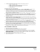
SMMC-3 CONTROL PANEL (ACCESS COVER REMOVED) SMTS-1 Zone 1 Sensor Input SMPS-1 (must be programmed To activate) Zone 1 Sensor Input SMAS-1 or SMGS-1 (Default) Zone 2 Sensor Input SMAS-1 or SMGS-1 Zone 2 Input for SMPS-1 Zone 1 Output Terminal Block Connector to Contactor Coil (Default) Zone 2 Output Fuse “Fuse OK” LED Zone 3 Sensor Input SMAS-1 or SMGS-1 Zone 3 Input for SMPS-1 Zone 3 Output 120VAC Power Connection W iring guide on back of terminal block cover PO.
SPECIFICATIONS Electrical Power Requirements 120 VAC, 50/60 hz, 480VA Mechanical NEMA 12 non-metallic enclosure Control Relays – Outputs 120 VAC, Pilot Duty, 120VA System Memory Non-Volatile: no data loss with a loss of system power Power Supply – Sensors 24 VAC, Class 3, 12VA Dimensions 12.375” W x 10.25” H x 4.75” D Temperature Sensor Supply 5 VDC, Class 2, 0.
LIMITED WARRANTY AND LIABILITY Nelson warrants that if there are any defects in material or workmanship in any heating cable or accessory during the first year (two years on MI or self regulating heaters) after the date of its purchase, we will provide new products to replace any defective items, or we will refund the purchase price paid for the accessory or cable, not including any labor or other installation costs.