
Owner's Manual


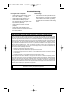

3-WAY WIRlNG DIAGRAM:
NEW CONSTRUCTION
6. Screw wall control into wall box using
the supplied screws. Leave wall
control in “OFF” mode until fan
installation is completed.
7. The wall control is supplied with a
white, ivory, and almond color switch
covers. Choose the finish that best
suits your needs and snap the cover
onto the wall control (Figure 7).
8. Next, install the other wall control into
the wall box containing the load wire.
Connect the black wire of the wall
control to the traveler wire(s) already
connected to the black wire (in the
other wall box). Secure with wire
connectors supplied.
9. Connect one black wire of the wall
control to the “load” (black) wire and
secure with wire connector supplied.
Check to see that all connections are tight
and that no bare wires are visible at the
wire connectors.
!
WARNING
HOT
BLACK
SW605
FAN/LIGHT
WALL
CONTROL
TRAVELER
WIRE
BLK
BLK
LOAD
BLACK
GROUND
NEUTRAL
RECEIVER LOCATED
WITHIN THE CEILING
COVER
EMERSON
®
EMERSON
®
HI
MED
LOW
FAN OFF
LIGHT
ONOFF
HI
MED
LOW
FAN OFF
LIGHT
ONOFF
Figure 8
3-WAY INSTALLATION
(On fan controlled by two different wall
controls) (See Figures 8 and 9.)
1. Disconnect electrical power to the
branch circuit at the circuit breaker or
fuse box before attempting to install the
ceiling fan wall control into the outlet box.
2. At all wall box locations remove
faceplates and screws from existing
controls. Pull controls out from wall
boxes and determine which wall box
contains the “hot” lead and which wall
box contains the “load” wire. Also,
identify traveler wires which are
common to both wall boxes.
Disconnect wires from existing controls
only. Do not attempt to disconnect any
wires not already connected to existing
controls.
3. Before installing wall control, place wall
control in “OFF” mode by pushing
“ON/OFF” switch to the “OFF” position.
4. Install a wall control in the wall box
containing the “hot” wire first. Connect
the black wire of the wall control to the
“hot” wire. Securely connect wires with
wire connectors supplied.
5. Connect one black wire of the wall
control to both remaining traveler wires
in the wall box and secure with wire
connector supplied.
NOTE: Retrofit 3-way installations are
likely to include two traveler wires
between the two wall boxes. In new
construction, only one traveler wire Is
required (See Figure 9).
Turning off wall switch is not sufficient.
To avoid possible electrical shock, be
sure electricity is turned off at the main
fuse or circuit breaker box before wiring.
All wiring must be in accordance with
National and Local codes and the ceiling
fan must be properly grounded as a
precaution against possible electrical
shock.
!
WARNING
Do not connect any neutral (white) wire to
this control. Incorrect wiring will damage
this control.
!
WARNING
8
BP7417 SR600 SR650 SW605 12/15/09 8:29 PM Page 8