
Data Sheet


Bulletin 71.4:SR8
5
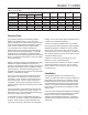
Capacity Data
The capacity information on the following pages is
based on four buildup factors, 10, 20, 30, and 40
percent. Buildup is the increase above setpoint required
to open and is usually stated in percentage of setpoint
value. Flow at setpoint (set ow) is approximately
10% of maximum ow. Greater capacities are
obtained with higher buildups over the relief pressure
setting, as shown in the capacity tables. To evaluate
the performance of a regulator, compare the stated
capacities at equivalent operating pressures and buildup
factors. Comparing the wide open C
v
does not consider
the overall accuracy.
Buildup is derived by applying the applicable percentage
buildup to the setpoint. Buildup of 10 percent on a
20 psig (1,4 bar) setpoint would be 2 psig (0,14 bar) for a
total pressure of 22 psig (1,5 bar). Capacity information
assumes full drop. For instances where full drop is not
applicable, it is easiest to use the Fisher
®
Sizing program
and the C
v
values listed in Table 5.
For the most accurate control, use the lowest range
spring that can be adjusted to the desired setpoint
(see Table 1 for part numbers of appropriate springs
for each body size). If closer control is necessary,
a regulator of larger capacity should be selected, so
that the necessary ow can be obtained with a smaller
offset factor.
It may be necessary to interpolate the capacity table
data to determine capacity for settings not given. To
maintain accuracy, it is important when interpolating to
stay within a spring range if possible.
An alternative method for interpolating capacities is
to use the C
v
as shown in Table 5 in the Fisher Sizing
Program. When using this method remember that
P
1
pressure is the sum of the setpoint and applicable
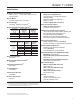
Table 4. Flow Coefcients
SIZE, NPS (DN)
WIDE OPEN COEFFECIENTS
C
1
K
m
F
L
X
T
F
d
C
g
C
v
C
s
1/2 (15) 27 1.4 1.3 19.1 0.54 0.73 0.23 0.40
3/4 (20) 70 3.1 3.5 22.8 0.61 0.78 0.33 0.41
1 (25) 202 7.2 10.1 28.1 0.63 0.79 0.50 0.42
1-1/2 x 1 (40 x 25) 216 7.6 10.8 28.4 0.60 0.77 0.51 0.42
1-1/2 (40) full port 309 10.9 15.5 28.4 0.68 0.82 0.51 0.40
2 (50) 962 34.4 48 28.0 0.60 0.78 0.49 0.32
3 (80) 1114 40.3 56 27.6 0.44 0.67 0.48 0.36
buildup. Do not use the wide open coefcients shown
in Table 4 for interpolating capacities.
Contact your nearest local Sales Ofce if you should
have any questions about selecting the proper regulator.
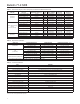
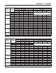
Regulating capacities in Table 6 are shown in SCFH
(60°F and 14.7 psia) of air at 60°F and normal cubic
meters per hour at 0°C and 1.01325 bar. For gases of
other specic gravities, divide by the square root of the
appropriate specic gravity.
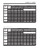
Capacities in Table 7 are in pounds per hour and
kilograms per hour of saturated steam.
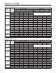
All water capacities in Tables 8 are shown in gallons
per minute and liters per minute. The K
m
values
listed in Table 4 can be used to predict choked ow
on liquid service.
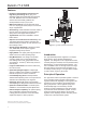
Installation
The Type SR8 regulator may be installed in any
position, as long as ow will be in the same direction as
that indicated by the body arrow. However, to ensure
self-draining (from inlet to outlet) the regulator should
be installed with the spring case in the upright vertical
position. The regulator should be installed so that the
spring case vent is protected from anything that might
interfere with it.
Emerson Process Management Regulator Technologies,
Inc. provides an instruction manual with every regulator
shipped. Refer to this for complete installation,
operation and maintenance instructions. Included is a
complete listing of individual parts and recommended
spare parts.