
Installation Guide

6
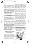
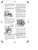
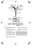
13. For Ceiling Fan Models F2100,
F2200, CF2300, CF2500 and
CF3900 Only. Locate and remove the
connector from the yellow wire from
the uplight (Figure 7). Separate,
untwist and unkink the 80” yellow wire
lead (supplied with the fan) and cut off
the connector from the end of the
wire. Strip 1/2-inch of insulation from
the end of this wire. Then join the 80”
yellow wire to the yellow wire from the
uplight using a wire connector
(supplied).
NOTE: The red and brown wires
coming from the top of the motor are
capped with wire connectors. DO NOT
remove these connectors.
2
1
80" YELLOW WIRE
BROWN
WIRE
DO NOT REMOVE THESE
WIRE CONNECTORS
RED WIRE
YELLOW WIRE
FROM UPLIGHT
REMOVE WIRE CONNECTOR
FROM YELLOW WIRE FROM
UPLIGHT
JOIN 80" YELLOW WIRE
USING WIRE CONNECTOR
Figure 7
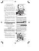
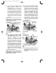
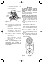
14. For Ceiling Fan Models CF4500
and CF4800 Only. Locate the two
yellow wires terminated by a wire
connector. Remove the wire
connector and separate the wires
(Figure 8). One yellow wire comes
from the motor coupling; cap the end
of this wire using a wire connector
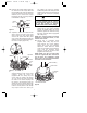
(supplied) (Figure 9). Separate,
untwist and unkink the 80” yellow wire
lead (supplied with the fan) and cut off
the connector from the end of the
wire. Strip 1/2-inch of insulation from
the end of this wire. Then join the 80”
yellow wire to the yellow wire from the
uplight using a wire connector
(supplied). (Figure 9).
NOTE: The red and brown wires
coming from the top of the motor are
capped with wire connectors. DO NOT
remove these connectors.
14A. For Ceiling Fan Models CF2400
Only. Cut the yellow wire midway
between the motor coupling and the
grommet in the inside of the housing
(orange wire on older CF2400
models). Cap the yellow wire coming
from the motor coupling using a wire
connector (supplied). Separate,
untwist and unkink the 80” yellow
wire lead (supplied with the fan) and
cut off the connector from the wire.
Strip 1/2-inch of insulation from the
end of this wire. Then join the 60”
yellow wire to the yellow wire coming
from the inside of the housing using
a wire connector.
YELLOW WIRE FROM
MOTOR COUPLING
BROWN
WIRE
DO NOT REMOVE THESE
WIRE CONNECTORS
RED WIRE
YELLOW WIRE
FROM UPLIGHT
REMOVE WIRE
CONNECTOR
MOTOR COUPLING
2
1
Figure 8
INSTALL WIRE
CONNECTOR
INSTALL 80" YELLOW WIRE
BROWN
WIRE
DO NOT REMOVE THESE
WIRE CONNECTORS
YELLOW WIRE
FROM UPLIGHT
RED WIRE
MOTOR
COUPLING
YELLOW WIRE
FROM MOTOR COUPLING
INSTALL
WIRE
CONNECTOR
3
2
4
Figure 9
15. For Ceiling Fan Models CF1 and
CF2800 Only. No wiring changes are
required on top of the motor; proceed
to Step 16.
BP7270-1 5/6/05 1:29 PM Page 6