
Installation Guide
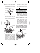

The hairpin clip must be properly
installed to prevent the clevis pin from
working loose. Pull on the downrod to
make sure the clevis pin is properly
installed.
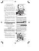
19. Install the setscrew (supplied with
ceiling fan) in the motor coupling
(Figure 11). While pulling up on the
downrod, tighten the setscrew using
the 5/32” setscrew wrench (supplied
with ceiling fan).
NOTE: The setscrew must be properly
installed as described above, or fan
wobble could result.
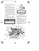
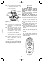
20. Screw two 1” threaded studs
(supplied with ceiling fan) into the
motor (Figure 12). Leave approxi-
mately 7/8” of the stud extending
above the motor. Slide the motor
cover over the downrod and rotate the
cover until the threaded studs
protrude; install two knurled knobs
(supplied with ceiling fan).
NOTE: Make sure the red and brown
leads are capped with wire connectors
and all wires are completely inside
motor cover and not pinched between
the motor cover and motor.
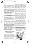
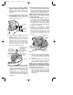
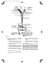
16. Remove the hanger ball by loosening
the setscrew in the hanger ball until
the ball falls freely down the downrod
(Figure 10). Remove the pin from the
downrod, then remove the hanger
ball. Retain the pin and hanger ball for
reinstallation in Step 22.
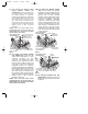
17. Separate, untwist and unkink the 80”
white, black, and blue motor lead
wires. Route the three motor leads
and the 80” yellow lead wire (used
only on fans with uplight) through the
downrod. Seat the downrod firmly in
the motor coupling (Figure 11).
18. Align the clevis pin holes in the
downrod with the holes in the motor
coupling. Install the clevis pin
(supplied with the ceiling fan) and
secure with the hairpin clip (Figure
11). The clevis pin must go through
the holes in the motor coupling and
the holes in the downrod. Push the
straight leg of the hairpin clip through
the hole near the end of the clevis pin
until the curved portion of the hairpin
clip snaps around the clevis pin.
DOWNROD
CLEVIS PIN
SETSCREW
HANGER
BALL
Figure 10
7
SETSCREW
CLEVIS PIN
MOTOR
COUPLING
DOWNROD
HAIRPIN
CLIP
DOWNROD
MOTOR COUPLING
CLEVIS
PIN
HAIRPIN
CLIP
SETSCREW
Figure 11
It is critical that the pin in the hanger ball
is properly installed and the setscrew
securely tightened. Failure to verify that
the pin and setscrew are properly
installed could result in the fan falling.
WARNING
!
KNURLED KNOB (2)
MOTOR COVER
1" THREADED
STUD (2)
RED AND BROWN WIRES
Figure 12
BP7270-1 5/6/05 1:29 PM Page 7