
Installation Guide

8
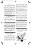
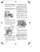
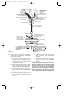
21. Position the ceiling cover over the
downrod (Figure 13). Be sure the
cover is oriented correctly, with the
large opening at the top.
22. Reinstall the hanger ball on the
downrod (Figure 13) as follows.
Route the motor leads through the
hanger ball and slide the hanger ball
over the downrod. Install the pin
through the holes at the top of the
downrod and slide the hanger ball up
the downrod, aligning the ball so the
pin is captured in the groove in the top
of the hanger ball. Pull the hanger ball
up tight against the pin and securely
tighten the setscrew in the hanger
ball. A loose setscrew could create
fan wobble.
23. Cut the wire leads from the downrod
approximately 6-inches above the
hanger ball. Strip back insulation 1/2-
inch from the end of the leads.
It is critical that the pin in the hanger ball
is properly installed and the setscrew
securely tightened. Failure to verify that
the pin and setscrew are properly
installed could result in the fan falling.
WARNING
!
SETSCREW
DOWNROD
PIN
HANGER BALL
CEILING
COVER
Figure 13
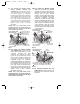
24. Install the hanger bracket and hang
the fan in accordance with the
instructions in the Ceiling Fan
Owner’s Manual.
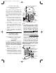
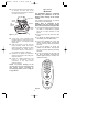
25. Pull the wire leads, coming from the
end of the downrod, and the supply
wires through the open side of the
hanger bracket. (Figure 14).
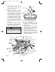
26. Position the SW105 Receiver in the
ceiling cover so that the flat side of
the receiver faces up and the open
portion of the receiver is to the right,
as shown in Figure
14.
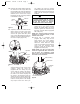
OUTLET BOX
BLACK SUPPLY WIRE
BLACK/WHITE RECEIVER WIRE
BLACK FAN WIRE
BLUE FAN WIRE
BLUE RECEIVER
WIRE
YELLOW FAN WIRE
YELLOW RECEIVER WIRE
CEILING COVER
WHITE RECEIVER WIRE
WHITE FAN WIRE
WIRE CONNECTOR
RECEIVER
WHITE SUPPLY
WIRE
SUPPLY GROUND
WIRE (GREEN OR
BARE)
HANGER BALL
GROUND WIRE
(GREEN)
HANGER BRACKET
GROUND WIRE
(GREEN)
HANGER BRACKET
BLACK RECEIVER WIRE
OPEN
PORTION OF
RECEIVER
HERE
Figure 14
BP7270-1 5/6/05 1:29 PM Page 8