Advanced User Guide U Universal Variable Speed AC Drive for induction and servo motors Part Number: 0471-0002-10 Issue: 10 www.controltechniques.
General Information The manufacturer accepts no liability for any consequences resulting from inappropriate, negligent or incorrect installation or adjustment of the optional operating parameters of the equipment or from mismatching the variable speed drive with the motor. The contents of this guide are believed to be correct at the time of printing.
Contents 1 Parameter structure.......................................................................................................6 1.1 1.2 1.3 Menu 0 ...................................................................................................................................................6 Advanced menus ...................................................................................................................................9 Solutions Modules .........................................
5.8 5.9 5.10 5.11 5.12 5.13 5.14 5.14.1 5.15 5.16 5.17 5.17.1 5.17.2 5.17.3 5.17.4 5.17.5 5.17.6 5.17.7 5.17.8 5.17.9 5.17.10 5.17.11 5.17.12 5.17.13 5.18 5.19 5.20 5.21 5.22 5.23 5.23.1 5.23.2 6 Menu 6: Sequencer and clock .......................................................................................................... 134 Menu 7: Analog I/O ........................................................................................................................... 150 Menu 8: Digital I/O ......
7.2 CT Modbus RTU specification ...........................................................................................................403 7.2.1 7.2.2 7.2.3 7.2.4 7.2.5 7.2.6 7.2.7 7.2.8 7.2.9 7.2.10 8 MODBUS RTU ........................................................................................................................................................ 404 Slave address .........................................................................................................................
Parameter structure 1 Keypad and display Parameter x.00 Parameter Advanced parameter description format descriptions Parameter structure Serial communications protocol Macros 1.1 Electronic nameplate Performance Rotor Flux Control (RFC) mode Menu 0 The drive initially powers up so that only menu 0 can be viewed. The up and down arrow buttons are used to navigate between parameters and once level 2 access (L2) has been enabled in Pr 0.
Parameter structure Keypad and display Parameter x.00 Parameter Advanced parameter description format descriptions Macros Serial communications protocol Electronic nameplate Performance Rotor Flux Control (RFC) mode Menu 0 is used to bring together various commonly used parameters for basic easy set up of the drive. All the parameters in menu 0 appear in other menus in the drive (denoted by {…}). Menus 11 and 22 can be used to change most of the parameters in menu 0.
Parameter structure Keypad and display Parameter x.00 Parameter Advanced parameter description format descriptions Macros Serial communications protocol Range(Ú) Parameter OL SV OL VT {11.36} 0 to 999 0 {11.42} {11.33} {11.32} {6.09} nonE (0), rEAd (1), Prog (2), AutO (3), boot (4) 200 (0), 400 (1), 575 (2), 690 (3) V 0.00 to 9999.99A 0 to 3 nonE (0) VT> Rated rpm autotune {5.16} 0.34 0.35 User security code Serial comms mode {11.30} {11.24} 0.36 Serial comms baud rate {11.25} 0.
Parameter structure 1.2 Keypad and display Parameter x.00 Parameter Advanced parameter description format descriptions Macros Serial communications protocol Electronic nameplate Performance Rotor Flux Control (RFC) mode Advanced menus The advanced menus consist of groups or parameters appropriate to a specific function or feature of the drive. These are accessible via the keypad, drive serial comms and Solutions Modules. All advanced menu parameters are only saved by setting Pr x.
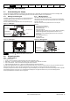
Parameter structure 2 Keypad and display Parameter x.00 Parameter Advanced parameter description format descriptions Serial comms protocol Macros Electronic nameplate Performance RFC mode Keypad and display 2.1 Understanding the display There are two keypads available for the Unidrive SP. The SM-Keypad has an LED display and the SM-Keypad Plus has an LCD display. Both keypads can be installed to the drive but the SM-Keypad Plus can also be remotely mounted on an enclosure door. 2.1.1 2.1.
Parameter structure Figure 2-4 Keypad and display Parameter x.
Parameter structure Keypad and display Parameter x.00 Parameter Advanced parameter description format descriptions 2.6 However with the second method an increasing rate of change does not take place when adjusting any other digit other than the least significant digit since a digit can only have one of 10 different values. Holding the Up or Down will cause an auto repeat and roll over to more significant digits but the rate of change is unaltered.
Parameter structure 2.7 Keypad and display Parameter x.00 Parameter Advanced parameter description format descriptions Parameter access level and security The parameter access level determines whether the user has access to menu 0 only or to all the advanced menus (menus 1 to 22) in addition to menu 0. Macros 2.7.3 Serial comms protocol Electronic nameplate Performance RFC mode User Security The User Security, when set, prevents write access to any of the parameters (other than Pr. 0.
Parameter structure 2.8 Keypad and display Parameter x.00 Parameter Advanced parameter description format descriptions Alarm and trip display An alarm can flash alternately with the data displayed on the 2nd row when one of the following conditions occur. If action is not taken to eliminate the alarm, except "Auto tune", "Lt" and "PLC", the drive may eventually trip. Alarms flash once every 640ms except "PLC" which flashes once every 10s.
Parameter structure 2.12 Keypad and display Parameter x.00 Parameter Advanced parameter description format descriptions Macros Serial comms protocol Electronic nameplate Performance RFC mode Special display functions The following special display functions are used. 1. If the second motor map is being used the decimal point second from the right of the first row is on. 2. When parameters are saved to a SMARTCARD the right-most decimal point on the first row flashes for 2 seconds.
Parameter structure 3 Keypad and display Parameter x.00 Parameter Advanced parameter description format descriptions Parameter x.00 3.2 Parameter x.00 is available in all menus and has the following functions. Value Action 1000 Save parameters when under voltage is not active (Pr 10.16 = 0) and 48V supply is not active (Pr 6.44 = 0).
Parameter structure Keypad and display Parameter x.00 Parameter Advanced parameter description format descriptions 7. When the drive mode is changed all data in the EEPROM is deleted and then restored with the defaults for the new mode. If the power is removed during a change of drive mode, an EEF trip is likely to occur on the next power-up. After a change of drive mode the power down save parameters are also saved.
Parameter structure 4 Keypad and display Parameter x.00 Parameter Advanced parameter description format descriptions Macros Serial comms protocol Electronic nameplate Performance RFC mode Parameter description format In the following sections descriptions are given for the advanced parameter set. With each parameter the following information block is given. 5.
Parameter structure 4.1 Keypad and display Parameter x.00 Parameter Advanced parameter description format descriptions Macros Serial comms protocol Electronic nameplate Performance RFC mode Parameter ranges and variable maximums: The two values provided define the minimum and maximum values for the given parameter. In some cases the parameter range is variable and dependant on either: • other parameters, • the drive rating, • drive mode • or a combination of these.
Parameter structure Keypad and display Parameter x.00 Parameter Advanced parameter description format descriptions Serial comms protocol Macros Maximum Electronic nameplate Performance RFC mode Definition Maximum current limit settings for motor map 1 This maximum current limit setting is the maximum applied to the current limit parameters in motor map 1.
Parameter structure Keypad and display Parameter x.00 Parameter Advanced parameter description format descriptions Maximum Macros Serial comms protocol Electronic nameplate Performance RFC mode Definition AC_VOLTAGE_MAX [930V] Maximum AC output voltage This maximum has been chosen to allow for maximum AC voltage that can be produced by the drive including quasi-square wave operation as follows: AC_VOLTAGE_MAX = 0.
Parameter structure Keypad and display Parameter x.
Parameter structure Table 4-3 Keypad and display Parameter x.
Parameter structure 4.2.3 Keypad and display Parameter x.00 Parameter Advanced parameter description format descriptions Macros Serial comms protocol Electronic nameplate Performance RFC mode Sources and destinations 1. Bit and non-bit parameters may be connected to each other as sources or destinations. The scaling is as described previously. 2. All new source and destination routing only changes to new set-up locations when the drive is reset. 3.
Parameter structure 4.3.3 Keypad and display Parameter x.00 Parameter Advanced parameter description format descriptions Macros Serial comms protocol Electronic nameplate Performance RFC mode Torque reference update rate The normal update rate for the torque reference (Pr 4.08) is 4ms, however it is possible to reduce the sample time to 250μs by selecting the reference from particular sources, but only in closed-loop vector or servo modes.
Parameter structure 5 Keypad and display Parameter x.00 Parameter Advanced parameter description format descriptions Advanced parameter descriptions 5.
Parameter structure 5.2 Keypad and display Parameter x.
Parameter structure Keypad and display Parameter x.00 Parameter Advanced parameter description format descriptions Feature Inertia compensation 2.38 5.12 4.22 3.18 Jog reference 1.05 2.19 2.29 Ke 5.33 Keypad reference 1.17 1.14 1.43 1.51 Kt 5.32 Limit switches 6.35 6.36 Local position reference 13.20 to 13.23 Logic function 1 9.01 9.04 9.05 9.06 Logic function 2 9.02 9.14 9.15 9.16 Low voltage supply 6.44 6.46 Mains loss 6.03 10.15 10.16 5.05 Marker pulse 3.32 3.31 Maximum speed 1.06 Menu 0 set up 11.
Parameter structure Keypad and display Feature Threshold detector 2 Time - filter change Time - powered up log Time - run log Torque Torque mode Trip detection Trip log Under voltage V/F mode Variable selector 1 Variable selector 2 Velocity feed forward Voltage controller Voltage mode Voltage rating Voltage supply Warning Zero speed indicator bit Parameter x.
Menu 1 5.3 Parameter structure Keypad and display Parameter x.00 Parameter Advanced parameter description format descriptions Macros Serial comms protocol Electronic nameplate Performance RFC mode Menu 1: Frequency/speed reference Menu 1 controls the main reference selection. When the drive operates in open-loop mode a frequency reference is produced, and when the drive operates in closed-loop vector or servo modes a speed reference is produced.
Parameter structure Keypad and display Parameter x.00 Parameter Advanced parameter description format descriptions JOG Macros RUN FORWARD Bipolar reference select Electronic nameplate Performance RFC mode Menu 1 RUN REVERSE Menu 8 Menu 6 Sequencer Jog selected indicator Serial comms protocol Sequencer (Menu 6) Reference in skip freq./speed band indicator 1.13 Menu 13 Position control 1.10 1.11 Feed-forward selected indicator Reverse selected indicator 1.12 1.40 1.
Menu 1 1.01 Drive modes Coding Parameter structure Keypad and display Parameter x.
Parameter structure Keypad and display Parameter x.00 Parameter Advanced parameter description format descriptions Serial comms protocol Macros Electronic nameplate Performance RFC mode Menu 1 Maximum reference clamp 1.06 Drive modes Open-loop, Closed-loop vector, Servo Bit SP FI DE Txt VM Coding DP ND RA NC NV PT 1 US RW BU 1 1 PS 1 Closed-loop vector and servo: VM = 1 Range Open-loop Closed-loop vector and Servo 0 to 3,000.
Menu 1 Parameter structure Keypad and display Parameter x.00 Parameter Advanced parameter description format descriptions Macros Serial comms protocol Electronic nameplate Performance RFC mode Analog input scaling The following diagrams show the scaling applied when analog inputs are used to define the reference and are routed via Pr 1.36 or Pr 1.37. SPEED_FREQ_MAX SPEED_FREQ_MAX Pr 1.07 -100% -100% 100% 100% -SPEED_FREQ_MAX Pr 1.10=0 ( unipolar mode) Pr 1.
Parameter structure Keypad and display 1.10 Drive modes Parameter Advanced parameter description format descriptions Serial comms protocol Macros Electronic nameplate Performance RFC mode Menu 1 Bipolar reference enable Open-loop, Closed-loop vector, Servo Bit Coding Parameter x.00 SP FI DE Txt VM DP ND RA NC NV PT 1 US RW BU 1 Default Open-loop, Closed-loop vector, Servo Update rate 4ms read PS 1 0 See Pr 1.08 on page 33. 1.11 Reference enabled indicator 1.
Parameter structure Menu 1 Keypad and display Parameter x.00 Parameter Advanced parameter description format descriptions Macros Serial comms protocol Electronic nameplate Performance RFC mode Keypad reference If Keypad reference is selected the drive sequencer is controlled directly by the keypad keys and the keypad reference parameter (Pr 1.17) is selected. The sequencing bits, Pr 6.30 to Pr 6.34, have no effect and jog is disabled. 1.
Parameter structure Keypad and display 1.17 Drive modes Coding Parameter x.00 Parameter Advanced parameter description format descriptions Serial comms protocol Macros Electronic nameplate Performance RFC mode Menu 1 Keypad control mode reference Open-loop, Closed-loop vector, Servo Bit SP FI DE Txt VM DP 1 1 ND RA NC NV 1 PT US RW BU 1 PS 1 Range Open-loop, Closed-loop vector, Servo ±SPEED_FREQ_MAX Hz/rpm Default Open-loop, Closed-loop vector, Servo 0.
Menu 1 1.20 Drive modes Coding Parameter structure Keypad and display Parameter x.
Parameter structure Keypad and display Parameter x.00 Parameter Advanced parameter description format descriptions 1.30 Skip reference band 1 1.32 Skip reference band 2 1.34 Skip reference band 3 Drive modes Coding Serial comms protocol Macros Electronic nameplate Performance RFC mode Menu 1 Open-loop, Closed-loop vector, Servo Bit SP FI DE Txt VM DP ND RA NC NV PT 1 US RW BU 1 1 PS 1 Closed-loop vector and servo DP = 0 Range Open-loop Closed-loop vector, Servo 0.0 to 25.
Parameter structure Menu 1 1.39 Keypad and display Parameter x.00 Parameter Advanced parameter description format descriptions Macros Serial comms protocol Electronic nameplate Performance RFC mode Velocity feed forward Drive modes Open-loop, Closed-loop vector, Servo Bit Coding SP FI DE Txt Range Open-loop Closed-loop vector, Servo Update rate 4ms read VM DP ND 1 1 RA NC NV 1 PT US RW BU PS 1 ±3,000.0 Hz ±40,000.
Parameter structure Keypad and display 1.49 Drive modes Parameter x.00 Parameter Advanced parameter description format descriptions Serial comms protocol Macros Electronic nameplate Performance RFC mode Menu 1 Reference selected indicator Open-loop, Closed-loop vector, Servo Bit Coding SP FI DE Txt VM DP ND RA 1 Range Open-loop, Closed-loop vector, Servo Update rate 4ms write NC NV 1 PT US RW BU 1 PS 1 1 to 5 Indicates the reference currently selected 1.
Parameter structure Menu 2 5.4 Keypad and display Parameter Parameter Advanced parameter x.00 description format descriptions Macros Serial comms protocol Electronic nameplate Performance RFC mode Menu 2: Ramps The pre-ramp frequency or speed reference passes through the ramp block controlled by menu 2 before being used by the drive to produce the basic output frequency (Open-loop modes), or as an input to the speed controller (Closed-loop vector or Servo modes).
Parameter structure Keypad and display Parameter x.00 Parameter Advanced parameter description format descriptions Macros Serial comms protocol Electronic nameplate Performance RFC mode Menu 2 * For more information refer to Pr 2.04 on page 44. ** For more information refer to Pr 2.06 on page 45. Deceleration rate select bits 2.37 2.36 2.35 Deceleration rate selector 2.20 1.50 2.29 Jog deceleration rate 1.13 Forward Decel.
Menu 2 2.01 Drive modes Coding Parameter structure Keypad and display Parameter Parameter Advanced parameter x.00 description format descriptions Bit SP FI DE Txt VM DP ND 1 1 1 Open-loop, Closed-loop vector, Servo 4ms write Coding Bit RA NC NV 1 PT US RW BU PS 1 ±SPEED_FREQ_MAX Hz/rpm SP FI DE Txt VM DP ND RA NC NV PT 1 US RW BU 1 RW, Bit, US Closed-loop vector and Servo Update rate 4ms read Coding RFC mode Closed-loop vector, Servo Default 2.
Parameter structure Keypad and display Parameter x.00 Parameter Advanced parameter description format descriptions Serial comms protocol Macros Electronic nameplate Performance RFC mode Menu 2 Controller operational DC Bus voltage Motor Speed Programmed deceleration rate t 2: Standard ramp with motor voltage boost This mode is the same as normal standard ramp mode except that the motor voltage is boosted by 20%. This increases the losses in the motor giving faster deceleration. 2.
Menu 2 Parameter structure Keypad and display Parameter Parameter Advanced parameter x.00 description format descriptions Macros Serial comms protocol Electronic nameplate Performance RFC mode Demanded Speed Acceleration Actual Speed Programmed ramp rate S ramp acceleration ramp T/2 T/2 T/2 T T/2 t T The time taken in seconds for the ramp output to change by frequency (Δf*) or speed (Δw*) is given below.
Parameter structure Keypad and display 02.09 Drive modes Parameter x.
Parameter structure Menu 2 Keypad and display 2.11 Acceleration rate 1 2.12 Acceleration rate 2 2.13 Acceleration rate 3 2.14 Acceleration rate 4 2.15 Acceleration rate 5 2.16 Acceleration rate 6 2.17 Acceleration rate 7 2.18 Acceleration rate 8 Drive modes Parameter Parameter Advanced parameter x.
Parameter structure Keypad and display Parameter x.00 Parameter Advanced parameter description format descriptions Macros Serial comms protocol Electronic nameplate Performance RFC mode Menu 2 When Pr 2.20 is set to 0 the deceleration ramp rate selected depends on the state of bit Pr 2.35 to Pr 2.37. These bits are for control by digital inputs such that ramp rates can be selected by external control. The ramp rate selected depends on the binary code generated by these bits as follows: 02.37 02.
Menu 2 Parameter structure Keypad and display Parameter Parameter Advanced parameter x.00 description format descriptions 2.32 Acceleration select bit 0 2.33 Acceleration select bit 1 2.34 Acceleration select bit 2 2.35 Deceleration select bit 0 2.36 Deceleration select bit 1 2.
Parameter structure 5.5 Keypad and display Parameter Parameter Advanced parameter x.00 description format descriptions Macros Serial comms protocol Electronic nameplate Performance RFC mode Menu 3 Menu 3: Slave frequency, speed feedback, speed control and regen operation Menu 3 relates to different functions depending on the drive mode selected as shown in the table below. The menus for some drive modes are significantly different and therefore the complete menu is covered in different sections.
Menu 3 Open-loop Parameter structure Keypad and display Parameter x.00 Parameter Advanced parameter description format descriptions Serial comms protocol Macros Electronic nameplate Performance RFC mode Parameter descriptions: Open-loop Figure 5-3 Menu 3 Open-loop logic diagram Drive encoder speed Drive encoder reference 3.27 15 way sub-D connector Drive encoder reference Any destination unprotected variable 3.46 parameter Maximum drive encoder reference 3.43 3.
Parameter structure Keypad and display 3.01 Drive modes Coding Parameter Parameter Advanced parameter x.00 description format descriptions Serial comms protocol Macros Electronic nameplate Performance RFC mode Menu 3 Open-loop Frequency slaving demand Open-loop Bit SP FI DE Txt VM 1 Range Open-loop Update rate 4ms write DP ND 1 1 RA NC NV 1 PT US RW BU PS 1 ±1000.
Menu 3 Open-loop 3.09 Drive modes Coding Parameter structure Keypad and display Parameter x.00 Parameter Advanced parameter description format descriptions Macros Serial comms protocol Electronic nameplate Performance RFC mode Absolute “at speed” select Open-loop, Closed-loop vector, Servo Bit SP FI DE Txt VM DP ND RA NC NV PT 1 US RW BU 1 Default Open-loop Update rate Background read PS 1 0 "At speed" flag (Pr 10.06) is set if the post-ramp reference (Pr 2.
Parameter structure Keypad and display 3.18 Drive modes Coding Parameter Parameter Advanced parameter x.00 description format descriptions Macros Serial comms protocol Electronic nameplate Performance RFC mode Menu 3 Open-loop F and D frequency slaving output Open-loop Bit SP FI DE Txt VM DP ND RA NC 1 Default Open-loop Update rate Background read NV PT US RW BU 1 PS 1 0 The frequency slaving output is in the form of F and D or quadrature A/B signals (Pr 3.
Menu 3 Closed-loop Parameter structure Keypad and display Parameter Parameter Advanced parameter x.00 description format descriptions Serial comms protocol Macros Electronic nameplate Performance RFC mode Parameter descriptions: Closed-loop vector and Servo Figure 5-4 Menu 3 Closed-loop logic diagram Hard speed reference Hard speed reference selector Reference enabled indicator Post-ramp reference 3.22 3.23 1.11 Final speed reference + + 2.01 3.
Parameter structure Keypad and display Parameter Parameter Advanced parameter x.00 description format descriptions Serial comms protocol Macros Electronic nameplate Performance RFC mode Menu 3 Closed-loop Speed controller gain select 3.16 Speed loop gains Speed error + (Kp1) 3.11 (Ki1) 3.13 (Kp2) 3.14 (Ki2) 3.03 3.04 _ Speed controller differential feedback gains Menu 4 (Kd2) (Kd1) 3.12 3.15 At zero speed Bipolar reference indicator select Zero speed threshold + 3.05 1.10 10.
Menu 3 Closed-loop Parameter structure 3.01 Keypad and display Parameter Parameter Advanced parameter x.
Parameter structure Keypad and display 3.03 Drive modes Coding Parameter Parameter Advanced parameter x.
Menu 3 Closed-loop Parameter structure 3.08 Drive modes Coding Keypad and display Parameter Parameter Advanced parameter x.00 description format descriptions Macros Serial comms protocol Electronic nameplate Performance RFC mode Overspeed threshold Closed-loop vector, Servo Bit SP FI DE Txt VM DP ND RA NC NV PT US RW BU 1 Range Closed-loop vector, Servo 0 to 40,0000 rpm Default Closed-loop vector, Servo 0 Update rate Background read 1 PS 1 If the speed feedback (Pr 3.
Parameter structure Keypad and display Parameter Parameter Advanced parameter x.00 description format descriptions 3.12 Speed controller differential feedback gain (Kd1) 3.15 Speed controller differential feedback gain (Kd2) Drive modes Serial comms protocol Macros Electronic nameplate Performance RFC mode Menu 3 Closed-loop Closed-loop vector, Servo Bit Coding SP FI DE Txt VM DP ND RA NC NV PT 5 US RW BU 1 Range Closed-loop vector, Servo 0.00000 to 0.
Menu 3 Closed-loop Parameter structure Keypad and display Parameter Parameter Advanced parameter x.00 description format descriptions Macros Serial comms protocol Electronic nameplate Performance RFC mode To analyze the performance of the speed controller it may be represented as an s-domain model as shown below. Kp w*(s) -1 rads w(s) -1 rads + + Kc _ _ Ki 1/s Kt L(s) + Ki.
Parameter structure Keypad and display Parameter Parameter Advanced parameter x.00 description format descriptions Serial comms protocol Macros Electronic nameplate Performance RFC mode Menu 3 Closed-loop 0: user set-up With the default value the user should enter the required speed controller gains. 1: Bandwidth set-up If bandwidth based set-up is required the following parameters must be set correctly: Pr 3.20 = required bandwidth, Pr 3.21 = required damping factor, Pr 3.
Menu 3 Closed-loop 3.21 Drive modes Coding Parameter structure Keypad and display Parameter Parameter Advanced parameter x.00 description format descriptions Macros Serial comms protocol Electronic nameplate Performance RFC mode Damping factor Closed-loop vector, Servo Bit SP FI DE Txt VM DP ND RA NC NV PT US RW BU 1 1 Range Closed-loop vector, Servo 0.0 to 10.0 Default Closed-loop vector, Servo 1.
Parameter structure Keypad and display Parameter Parameter Advanced parameter x.00 description format descriptions Serial comms protocol Macros Electronic nameplate Performance RFC mode Menu 3 Closed-loop When closed-loop vector mode without position feedback is used a filter with a 4ms time constant is automatically included in the speed feedback as this is required for this system to operate correctly.
Menu 3 Closed-loop Parameter structure Keypad and display Parameter Parameter Advanced parameter x.00 description format descriptions Macros Serial comms protocol Electronic nameplate Performance RFC mode The motor will move to one of a number of positions defined by the number of motor pole pairs (i.e. 3 positions for a six pole motor, etc). The encoder should be adjusted so that the U commutation signal is high, W is low and V is toggling in one of these positions.
Parameter structure Keypad and display Parameter Parameter Advanced parameter x.00 description format descriptions Serial comms protocol Macros Electronic nameplate Performance RFC mode Menu 3 All modes Parameters common to open-loop and closed-loop modes 3.27 Drive modes Coding Drive encoder speed feedback Open-loop, Closed-loop vector, Servo Bit SP FI DE Txt VM 1 DP ND 1 1 Range Open-loop, Closed-loop vector, Servo Update rate 4ms write RA NC NV 1 PT US RW BU PS 1 ±40,000.
Menu 3 All modes 3.32 Drive modes Coding Parameter structure Keypad and display Parameter x.
Parameter structure Keypad and display 3.34 Drive modes Coding Parameter Parameter Advanced parameter x.
Menu 3 All modes 3.35 Drive modes Parameter structure Keypad and display Parameter x.
Parameter structure Keypad and display Parameter Parameter Advanced parameter x.00 description format descriptions Macros Serial comms protocol Electronic nameplate Performance RFC mode Menu 3 All modes Any baud rate can be used when encoder comms is used with a SINCOS encoder to obtain the absolute position during initialization. When encoder comms is used alone(EnDat or SSI selected with Pr 3.
Menu 3 All modes Parameter structure Keypad and display Parameter x.00 Parameter Advanced parameter description format descriptions Macros Serial comms protocol Electronic nameplate Performance RFC mode SSI comms The whole position must be obtained from an SSI encoder before it can be used by the drive, therefore the time for the single turn position and the time for the whole message are the same. Time to obtain the position= (Number of turns bits + Single turn resolution + 1) x T = tD + (Pr 3.
Parameter structure Keypad and display Parameter Parameter Advanced parameter x.00 description format descriptions Macros Serial comms protocol Electronic nameplate Performance RFC mode Menu 3 All modes All SINCOS encoders and encoders using communications must be initialized before their position data can be used. The encoder is automatically initialized at power-up, after trips Enc1 to Enc8 or Enc11 to Enc17 are reset, and when the initialization (Pr 3.47) is set to 1.
Menu 3 All modes Parameter structure Keypad and display Parameter x.00 Parameter Advanced parameter description format descriptions Macros Serial comms protocol Electronic nameplate Performance RFC mode This problem should not occur with EnDat encoders because three consecutive corrupted messages at the slowest sample rate (i.e. 25μs) would be required even at the maximum speed of 40,000rpm before the change of position would be the required 0.
Parameter structure Keypad and display Parameter Parameter Advanced parameter x.00 description format descriptions Encoders Macros Serial comms protocol Electronic nameplate Performance Reason for error RFC mode Menu 3 All modes Drive trip SC.EnDat, EnDat The number of encoder turns read from the encoder during autoconfiguration is not a power of 2 Enc13 SC.
Menu 3 All modes Parameter structure Keypad and display Parameter x.00 Parameter Advanced parameter description format descriptions Macros Serial comms protocol Electronic nameplate Performance RFC mode To ensure that an Enc1 trip is not initiated when the internal 24V is overloaded, and subsequently switched off by the drive, there is a delay of 40ms in the detection of Enc1 trip.
Parameter structure Keypad and display Parameter Parameter Advanced parameter x.00 description format descriptions Serial comms protocol Macros Electronic nameplate Performance RFC mode Menu 3 All modes In closed-loop vector mode, if Pr 3.24 is set to 1 or 3 so that the drive is operating without position feedback, this parameter also defines a filter on the output of the speed estimator which is used as the speed feedback.
Menu 3 All modes Parameter structure Keypad and display Parameter x.00 Parameter Advanced parameter description format descriptions Macros Serial comms protocol Electronic nameplate Performance RFC mode At power-up Pr 3.48 is initially zero, but is set to one when the drive encoder and any encoders connected to position category modules have been initialized. The drive cannot be enabled until this parameter is one.
Parameter structure Keypad and display Parameter Parameter Advanced parameter x.00 description format descriptions Macros Serial comms protocol Electronic nameplate Performance RFC mode Menu 3 All modes The actual encoder comms buffer is 16 bytes long and any messages that exceed this length (including the checksum added for Hiperface) will cause an error.
Menu 3 All modes Parameter structure Keypad and display Parameter x.00 Parameter Advanced parameter description format descriptions Macros Serial comms protocol Electronic nameplate Performance RFC mode Example of Hiperface transfer: Delete data field Transfer the "delete data field" message to the encoder comms buffer by writing the sequence of words shown in the table below to Pr 90.22. A check should be carried out before each word is written to ensure that the parameter is zero (i.e.
Parameter structure Keypad and display Parameter Parameter Advanced parameter x.00 description format descriptions Macros Serial comms protocol Electronic nameplate Performance RFC mode Menu 3 All modes Transfer the "read position" message to the encoder comms buffer by writing the sequence of words shown in the table below to Pr 90.22. A check should be carried out before each word is written to ensure that the parameter is zero (i.e. the drive has taken any previous data).
Menu 3 Regen Parameter structure Keypad and display Parameter Parameter Advanced parameter x.00 description format descriptions Macros Serial comms protocol Electronic nameplate Performance RFC mode Parameter descriptions: Regen Figure 5-5 Menu 3 Regen logic diagram Softstart contactor closed Regen sequencer 3.08 25 Enable input Close soft start contactor 3.04 31 3.07 Regen restart mode 3.03 2.01 Power feed-forward compensation 3.05 Enable motor drive 42 3.
Parameter structure Keypad and display Parameter Parameter Advanced parameter x.00 description format descriptions Serial comms protocol Macros Electronic nameplate Performance RFC mode Menu 3 Regen The drive checks for mains loss either by monitoring the d.c. link or additionally when the inverter is active by an internal estimate of the a.c. supply level. The detection levels used for different drive voltage ratings are given in the following table.
Menu 3 Regen Parameter structure Keypad and display Parameter Parameter Advanced parameter x.00 description format descriptions Macros Serial comms protocol Electronic nameplate Performance RFC mode Input inductance 3.02 Drive modes Coding Regen Bit SP FI DE Range Regen Update rate Background write Txt VM DP ND 3 1 RA NC NV PT 1 US RW BU 1 PS 1 0.000 to 500.000mH At power-up this parameter is zero.
Parameter structure Keypad and display 3.05 Drive modes Coding Parameter Parameter Advanced parameter x.
Menu 3 Regen Parameter structure Keypad and display Parameter Parameter Advanced parameter x.00 description format descriptions Macros Serial comms protocol Electronic nameplate Performance RFC mode ch3: dT= 194ms dV=2.24 V Active regen unit current Regen unit DC bus voltage 50ms/div The example shown is for a very rapid load change where the torque reference of the motor drive has been changed instantly from one value to another.
Parameter structure Keypad and display 3.08 Drive modes Coding Parameter Parameter Advanced parameter x.00 description format descriptions Serial comms protocol Macros Electronic nameplate Performance RFC mode Menu 3 Regen Contactor closed Regen Bit SP FI DE Txt VM DP 1 ND RA NC 1 Default Regen Update rate 4ms read NV PT US RW BU PS 1 0 When regen mode is selected Pr 3.08 is the destination from digital I/O2 (T25) with the I/O set up as an input as default.
Parameter structure Menu 4 5.6 Keypad and display Parameter Parameter Advanced parameter x.00 description format descriptions Macros Serial comms protocol Electronic nameplate Performance RFC mode Menu 4: Torque and current control The scaling of the current feedback is based on the rating of the drive as follows: Level x current scaling (Kc) Over-current trip 1/0.45 = 2.22 Open-loop peak limit 1.75 Closed-loop vector, Servo and Regen maximum standard operating current 1.
Parameter structure Keypad and display Parameter Parameter Advanced parameter x.00 description format descriptions Macros Serial comms protocol Electronic nameplate Performance RFC mode Menu 4 SPMAxxxx and SPMDxxxx drive modules can be connected in parallel provided all power modules have the same voltage and current rating to make a larger drive. The currents are then defined as follows: Current scaling (Kc) Kc is the sum of Kc for all the modules..
Parameter structure Menu 4 Keypad and display Parameter Parameter Advanced parameter x.00 description format descriptions Macros Serial comms protocol Electronic nameplate Performance RFC mode The rated active and rated magnetising currents are calculated from the power factor (Pr 5.10) and motor rated current (Pr 5.
Parameter structure Keypad and display Parameter Parameter Advanced parameter x.00 description format descriptions Macros Serial comms protocol Electronic nameplate Performance RFC mode Menu 4 Where: Rs is the motor stator resistance (Pr 5.17) fR is the rated frequency (Pr 5.06) σLs is the transient inductance (H) (Pr 5.24 / 1000) VR is the rated voltage (Pr 5.
Parameter structure Menu 4 Keypad and display Parameter Parameter Advanced parameter x.00 description format descriptions Macros Serial comms protocol Electronic nameplate Performance RFC mode Where: Motor rated current is given by Pr 5.07 (MOTOR2_CURRENT_LIMIT_MAX is calculated from the motor map 2 parameters) The Maximum current is either (1.75 x Kc) when the rated current set by Pr 5.07 (or Pr 21.
Parameter structure Keypad and display Parameter Parameter Advanced parameter x.00 description format descriptions Macros Serial comms protocol Electronic nameplate Performance RFC mode Menu 4 5.6.5 Parameter descriptions Parameter descriptions: Open-loop Figure 5-6 Menu 4 Open-loop logic diagram Menu 2 ramp controller Pre ramp reference Torque mode selector* 4.11 + 1.03 2.01 Post ramp reference + Motor frequency Motor map 2.01 5.01 10.09 Current limit active Current loop 4.
Parameter structure Menu 4 Keypad and display Parameter Parameter Advanced parameter x.00 description format descriptions Serial comms protocol Macros Electronic nameplate Performance RFC mode Parameter descriptions: Closed-loop vector Figure 5-7 Menu 4 Closed-loop logic diagram Inertia compensation torque 2.38 Speed feedback 3.02 4.22 Speed loop output _ Final speed demand 3.01 + 3.04 Inertia compensation enable Torque mode selector* + + 0 1 2 3 4 + Speed over-ride level Pre1.
Parameter structure Keypad and display Parameter Parameter Advanced parameter x.00 description format descriptions Macros Serial comms protocol Electronic nameplate Performance RFC mode Menu 4 Parameter descriptions: Servo Figure 5-8 Menu 4 Servo logic diagram Inertia compensation torque 2.38 Speed feedback 3.02 4.22 Speed loop output _ Final speed demand 3.01 + 3.04 + Speed over-ride level Pre1.03 ramp reference Zero speed threshold 3.05 Torque reference* 4.
Parameter structure Menu 4 Figure 5-9 Keypad and display Parameter Parameter Advanced parameter x.00 description format descriptions Macros Serial comms protocol Electronic nameplate Performance RFC mode Menu 4 Regen logic diagram Reactive current reference + 4.08 Current controller kp gain 4.14 Current controller ki gain _ Current demand Real current demand from Menu 3 4.13 + 4.04 2.01 4.13 Current controller kp gain 4.
Parameter structure Keypad and display 4.01 Parameter Parameter Advanced parameter x.00 description format descriptions Serial comms protocol Macros Electronic nameplate Performance RFC mode Menu 4 Current magnitude Drive modes Open-loop, Closed-loop vector, Servo, Regen Bit Coding SP FI DE Txt 1 VM DP ND 1 2 1 Range Open-loop, Closed-loop vector, Servo, Regen Update rate 4ms write RA NC NV PT 1 US RW BU 1 PS 1 0 to DRIVE_CURRENT_MAX A This parameter is the r.m.s.
Menu 4 Parameter structure 4.03 Drive modes Coding Keypad and display Parameter Parameter Advanced parameter x.
Parameter structure Keypad and display 4.07 Parameter Parameter Advanced parameter x.
Menu 4 Parameter structure 4.08 Keypad and display Parameter Parameter Advanced parameter x.00 description format descriptions Macros Serial comms protocol Electronic nameplate Performance RFC mode Reactive current reference Drive modes Regen Coding Bit Range Regen ±REGEN_REACTIVE_MAX % Default Regen 0.
Parameter structure Keypad and display Parameter Parameter Advanced parameter x.00 description format descriptions Macros Serial comms protocol Electronic nameplate Performance RFC mode Menu 4 Closed loop vector and Servo When this parameter is set to 1, 2 or 3 the ramps are not active while the drive is in the run state. When the drive is taken out of the run state, but not disabled, the appropriate stopping mode is used. It is recommended that coast stopping or stopping without ramps are used.
Parameter structure Menu 4 Keypad and display Parameter Parameter Advanced parameter x.
Parameter structure Keypad and display 4.14 Drive modes Coding Parameter Parameter Advanced parameter x.
Menu 4 Parameter structure Keypad and display Parameter Parameter Advanced parameter x.00 description format descriptions Macros Serial comms protocol Electronic nameplate Performance RFC mode Closed-loop vector and Servo The proportional gain Kp (Pr 4.13) is the most critical value in controlling the performance of the current controllers. Either the value can be set by auto-tuning (see Pr 5.
Parameter structure Keypad and display Parameter Parameter Advanced parameter x.00 description format descriptions Serial comms protocol Macros Unidrive Electronic nameplate Performance RFC mode Menu 4 Unidrive SP Switching freq Proportional gain Integral gain Switching freq Proportional gain 3kHz Pr 4.13 x 0.5 Pr 4.14 3kHz Pr 4.13 Integral gain Pr 4.14 4.5kHz Pr 4.13 x 0.75 Pr 4.14 4kHz Pr 4.13 x 1.5 Pr 4.14 6kHz Pr 4.13 Pr 4.14 6kHz Pr 4.13 x 2 Pr 4.14 9kHz Pr 4.13 x 0.
Menu 4 Parameter structure Keypad and display Motor total current (Pr 4.01) as a percentage of motor rated current Parameter Parameter Advanced parameter x.00 description format descriptions Macros Serial comms protocol Electronic nameplate Performance RFC mode It2 protection operates in this region 105% 70% Max. permissible continuous current Pr 4.25 = 0 Pr 4.25 = 1 50% 100% Motor speed as a percentage of base speed Open loop: Proportion of rated frequency Pr 5.06.
Parameter structure Keypad and display Parameter Parameter Advanced parameter x.00 description format descriptions Serial comms protocol Macros Electronic nameplate Performance RFC mode Menu 4 The thermal protection system can be used in regen mode to protect the input inductors. The rated current (Pr 5.07) should be set to the rated current for the inductors.
Menu 4 4.22 Drive modes Coding Parameter structure Keypad and display Parameter Parameter Advanced parameter x.
Parameter structure 5.7 Keypad and display Parameter Parameter Advanced parameter x.00 description format descriptions Macros Serial comms protocol Electronic nameplate Performance RFC mode Menu 5 Menu 5: Motor control Open loop Figure 5-10 Menu 5 Open-loop logic diagram 5.14 Autotune L1 L2 L3 Voltage mode 5.12 Frequency slaving enable Slave frequency demand Motormap 5.06 3.13 5.07 3.01 5.08 5.09 Post ramp reference 5.10 + 2.01 5.
Menu 5 Parameter structure Keypad and display Parameter x.00 Parameter Advanced parameter description format descriptions Macros Serial comms protocol Electronic nameplate Performance RFC mode Closed-loop vector and Servo Figure 5-11 Menu 5 Closed-loop logic diagram 5.01 Flux Calculator Motor rated current Motor number 5.11 of poles Motor stator 5.17 resistance Motor transient 5.24 inductance 5.07 Speed feedback Position feedback ∫ 3.
Parameter structure Keypad and display Parameter Parameter Advanced parameter x.00 description format descriptions Macros Serial comms protocol Electronic nameplate Performance RFC mode Menu 5 DC bus voltage 5.05 Voltage reference U Modulator 5.18 Maximum switching frequency V 5.35 Disable auto switching frequencychange W Flux Controller 5.09 5.21 Motor rated voltage Field gain reduction Closed-Loop Vector Dynamic V/f / 5.13 flux optimisation enable Motor full load rated speed 5.
Menu 5 Parameter structure Keypad and display Parameter x.00 Parameter Advanced parameter description format descriptions Macros Serial comms protocol DC bus voltage Output voltage 5.05 2.01 5.02 2.01 Electronic nameplate Performance RFC mode Regen Figure 5-12 Menu 5 Regen logic diagram 5.07 Motor rated current 5.35 Disable auto switching frequency change Current control Menu 4 Reference frame transformation Modulator 5.18 5.
Parameter structure Keypad and display 5.01 Drive modes Parameter Parameter Advanced parameter x.00 description format descriptions Serial comms protocol Macros Electronic nameplate Performance RFC mode Menu 5 Output frequency Open-loop, Closed-loop vector Bit SP Coding FI DE Txt 1 VM DP ND 1 1 1 RA NC NV PT 1 US RW BU PS 1 RFC: VM = 0 Range Open-loop RFC Update rate 250μs write ±SPEED_FREQ_MAX Hz ±1250.
Menu 5 Parameter structure 5.05 Drive modes Keypad and display Parameter x.
Parameter structure Keypad and display 5.08 Drive modes Parameter Parameter Advanced parameter x.00 description format descriptions Serial comms protocol Macros Electronic nameplate Performance RFC mode Menu 5 Rated load rpm / Rated speed Open-loop, Closed-loop vector, Servo Bit SP FI DE Txt VM DP ND RA NC NV PT US RW BU Coding 1 1 PS 1 Closed-loop vector and Servo DP=2 Range Open-loop, Closed-loop 0 to 180,000 rpm 0.00 to 40,000.
Menu 5 Parameter structure Keypad and display Parameter x.00 Parameter Advanced parameter description format descriptions Macros Serial comms protocol Electronic nameplate Performance RFC mode When the drive operates between rated frequency/4 and rated frequency/2 the Rs compensation is gradually reduced to zero as the frequency increases. For the vector modes to operate correctly the stator resistance (Pr 5.17), motor rated power factor (Pr 5.10) and voltage offset (Pr 5.
Parameter structure Keypad and display 5.10 Drive modes Coding Parameter Parameter Advanced parameter x.00 description format descriptions Serial comms protocol Macros Electronic nameplate Performance RFC mode Menu 5 Rated power factor Open-loop, Closed-loop vector Bit SP FI DE Txt VM DP ND 3 RA NC NV PT 1 US RW BU 1 Range Open-loop, Closed-loop 0.000 to 1.000 Default Open-loop, Closed-loop vector 0.850 Second motor parameter Open-loop, Closed-loop vector Pr 21.
Menu 5 Parameter structure Keypad and display Parameter x.00 Parameter Advanced parameter description format descriptions Macros Serial comms protocol Electronic nameplate Performance RFC mode (If Pr 5.12 is set to 4 in closed-loop vector mode or 6 in servo mode then no test is carried out, but the current loop gains are re-calculated. For these actions the drive does not need to be enabled).
Parameter structure Keypad and display Parameter Parameter Advanced parameter x.00 description format descriptions Macros Serial comms protocol Electronic nameplate Performance RFC mode Menu 5 1. Stationary test • A stationary test is performed to measure the stator resistance (Pr 5.17) • Pr 5.17 is saved to EEPROM. • A stationary test is performed to measure the transient inductance (Pr 5.24). When this test is complete the current loop gains (Pr 4.13 and Pr 4.
Menu 5 Parameter structure Keypad and display Parameter x.00 Parameter Advanced parameter description format descriptions Macros Serial comms protocol Electronic nameplate Performance RFC mode 2. Normal low speed test • The motor is rotated by 2 electrical revolutions (i.e. up to 2 mechanical revolutions) in the forward direction. The drive applies rated current to the motor during the test and measures the encoder phase angle (Pr 3.25).
Parameter structure Keypad and display Parameter Parameter Advanced parameter x.00 description format descriptions Macros Serial comms protocol Electronic nameplate Performance RFC mode Menu 5 The current controllers are used to perform this test, however, the default gains may be too high. It is not possible to carry out the necessary test to set up the current controllers before the phasing angle is known. If the gains are too high the minimal movement phasing test may cause an OI.AC trip.
Menu 5 5.13 Drive modes Coding Parameter structure Keypad and display Parameter x.
Parameter structure Keypad and display 5.14 Parameter Parameter Advanced parameter x.00 description format descriptions Serial comms protocol Macros Electronic nameplate Performance RFC mode Menu 5 Action on enable Drive modes Servo Bit Coding SP FI DE TE VM DP ND RA NC NV PT 1 US RW BU 1 Range Servo 0 to 2 Default Servo 0 Update rate Background read 1 PS 1 This parameter defines the action taken on enable as follows: 0: nonE No action.
Parameter structure Menu 5 5.17 Keypad and display Parameter x.00 Parameter Advanced parameter description format descriptions Macros Serial comms protocol Electronic nameplate Performance RFC mode Stator resistance Drive modes Open-loop, Closed-loop vector, Servo Bit Coding SP FI DE Txt VM DP ND RA 3 NC NV PT 1 US RW BU 1 Range Open-loop, Closed-loop vector, Servo 0.000 to 65.000 Default Open-loop, Closed-loop vector, Servo 0.
Parameter structure Keypad and display Parameter Parameter Advanced parameter x.
Menu 5 5.19 Drive modes Coding Parameter structure Keypad and display Parameter x.00 Parameter Advanced parameter description format descriptions Macros Serial comms protocol Electronic nameplate Performance RFC mode High stability space vector modulation Open-loop Bit SP FI DE Txt VM DP ND RA NC NV PT 1 US RW BU 1 Default Open-loop, Update rate Background read PS 1 0 Normally the drive will use space vector modulation to produce the IGBT control signals.
Parameter structure Keypad and display 5.22 Drive modes Coding Parameter Parameter Advanced parameter x.00 description format descriptions Macros Serial comms protocol Electronic nameplate Performance RFC mode Menu 5 Enable high speed servo mode Servo Bit SP FI DE Txt VM DP ND RA NC NV PT 1 US RW BU 1 Default Servo Update rate Background read PS 1 0 High speed servo mode is not enabled as default.
Menu 5 Parameter structure 5.24 Keypad and display Parameter x.00 Parameter Advanced parameter description format descriptions Macros Serial comms protocol Electronic nameplate Performance RFC mode Transient inductance (σLs) Drive modes Open-loop, Closed-loop vector, Servo Coding Bit SP FI DE Txt VM DP ND RA 3 NC NV PT 1 US RW BU 1 Range Open-loop, Closed-loop vector, Servo 0.000 to 500.000 mH Default Open-loop, Closed-loop vector, Servo 0.
Parameter structure Keypad and display 5.27 Drive modes Coding Parameter Parameter Advanced parameter x.00 description format descriptions Macros Serial comms protocol Electronic nameplate Performance RFC mode Menu 5 Enable slip compensation Open-loop Bit SP FI DE Txt VM DP ND RA NC NV PT 1 US RW BU 1 Default Open-loop Update rate Background read 1 PS 1 1 The level of slip compensation is set by the rated frequency and rated speed parameters.
Menu 5 Parameter structure Keypad and display Parameter x.00 Parameter Advanced parameter description format descriptions Macros Serial comms protocol Electronic nameplate Performance RFC mode The drive can include the effects of saturation by representing the flux producing current to flux characteristic as a series of three lines as shown below: flux (%) 100% Pr 5.30 Pr 5.29 50 75 100 i_mag (%) If Pr 5.29 and Pr 5.
Parameter structure Keypad and display 5.33 Drive modes Coding Parameter Parameter Advanced parameter x.00 description format descriptions Macros Serial comms protocol Electronic nameplate Performance RFC mode Menu 5 Motor volts per 1000rpm (Ke) Servo Bit SP FI DE Txt VM DP ND RA NC NV PT US RW BU 1 Range Servo 0 to 10,000 Default Servo 98 Second motor parameter Servo Pr 21.
Menu 5 5.37 Drive modes Parameter structure Keypad and display Parameter x.00 Parameter Advanced parameter description format descriptions Macros Serial comms protocol Electronic nameplate Performance RFC mode Actual switching frequency Open-loop, Closed-loop vector, Servo Bit Coding SP FI DE TE VM DP 1 ND RA 1 Range Open-loop, Closed-loop vector, Servo Update rate Background write NC NV 1 PT US RW BU 1 PS 1 0 to 7 Pr 5.
Parameter structure Keypad and display 5.40 Drive modes Coding Parameter Parameter Advanced parameter x.00 description format descriptions Macros Serial comms protocol Electronic nameplate Performance RFC mode Menu 5 Spin start boost Open-loop, Closed-loop vector Bit SP FI DE TE VM DP ND RA NC 1 NV PT US RW BU 1 Range Open-loop, Closed-loop vector 0.0 to 10.0 Default Open-loop, Closed-loop vector 1.0 Update rate Background read 1 PS 1 If Pr 6.
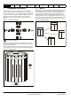
Parameter structure Menu 6 5.8 Keypad and display Parameter Parameter Advanced parameter x.00 description format descriptions Macros Serial comms protocol Electronic nameplate Performance RFC mode Menu 6: Sequencer and clock Figure 5-13 Menu 6 logic diagram Control word enable Stop / Start select*** 6.43 Control word 6.42 6.04 Sequencer Drive enable 6.15 Run forward 6.30 T25 digital I/O 2 Jog forward 6.31 Run reverse 6.32 T26 digital I/O 3 Forward / Reverse 6.33 Menu 8 6.
Parameter structure Keypad and display 6.01 Parameter Parameter Advanced parameter x.
Parameter structure Menu 6 1: Keypad and display Parameter Parameter Advanced parameter x.00 description format descriptions Macros Serial comms protocol Electronic nameplate Performance RFC mode Stop Open-loop The action taken by the drive is the same as for ride through mode, except the ramp down rate is at least as fast as the deceleration ramp setting and the drive will continue to decelerate and stop even if the mains is re-applied.
Parameter structure Keypad and display 6.06 Drive modes Coding Parameter Parameter Advanced parameter x.00 description format descriptions Macros Serial comms protocol Electronic nameplate Performance RFC mode Menu 6 Injection braking level Open-loop Bit SP FI DE TE VM DP ND 1 RA NC NV PT 1 US RW BU 1 Range Open-loop 0 to 150.0 % Default Open-loop 100.
Menu 6 6.09 Drive modes Coding Parameter structure Keypad and display Parameter Parameter Advanced parameter x.
Parameter structure Keypad and display Parameter Parameter Advanced parameter x.00 description format descriptions Serial comms protocol Macros Electronic nameplate Performance RFC mode Menu 6 Sequencer latching enabled (Pr 6.40=1) If the Stop key is pressed when the stop key is enabled (Pr 6.12=1) or when the drive is tripped the sequencer run is removed, and so the drive stops or remains stopped respectively.
Menu 6 6.18 Drive modes Coding Parameter structure Keypad and display Parameter Parameter Advanced parameter x.00 description format descriptions Bit SP FI DE TE VM DP ND RA NC NV PT 1 US RW BU 1 0 to 30,000 hrs Default Open-loop, Closed-loop vector, Servo, Regen 0 Update rate Background read Coding Electronic nameplate Performance RFC mode Open-loop, Closed-loop vector, Servo, Regen Open-loop, Closed-loop vector, Servo, Regen 6.
Parameter structure Keypad and display 6.23 Drive modes Coding Parameter Parameter Advanced parameter x.00 description format descriptions Serial comms protocol Macros Electronic nameplate Performance RFC mode Menu 6 Run time: hours.minutes Open-loop, Closed-loop vector, Servo, Regen Bit SP FI DE TE VM DP ND 2 1 Range Open-loop, Closed-loop vector, Servo, Regen Update rate Background write RA NC NV 1 PT US RW BU 1 1 PS 1 0 to 23.59 Hours.
Menu 6 6.28 Drive modes Coding Parameter structure Keypad and display Parameter Parameter Advanced parameter x.
Parameter structure Keypad and display 6.32 Drive modes Coding Parameter Parameter Advanced parameter x.00 description format descriptions Bit SP FI DE TE VM DP RFC mode Menu 6 NC NV PT US RW BU PS 1 0 Open-loop, Closed-loop vector, Servo Bit SP FI DE TE VM DP ND RA 1 NC NV PT US RW BU 1 Open-loop, Closed-loop vector, Servo Update rate 4ms read Coding Performance Sequencing bit: Forward/reverse Default Drive modes RA 1 4ms read 6.
Menu 6 6.36 Drive modes Coding Parameter structure Keypad and display Parameter Parameter Advanced parameter x.
Parameter structure Keypad and display 6.41 Parameter Parameter Advanced parameter x.
Parameter structure Menu 6 Keypad and display Parameter Parameter Advanced parameter x.00 description format descriptions Macros Serial comms protocol Electronic nameplate Performance RFC mode Bits 0-7 and bit 9: sequencing control When the control word is enabled (Pr 6.43 = 1), and the Auto/manual bit (bit7) are both one, bits 0 to 6 and bit 9 of the control word become active.
Parameter structure Keypad and display Parameter Parameter Advanced parameter x.00 description format descriptions Macros Serial comms protocol Electronic nameplate Performance RFC mode Menu 6 Full scale voltage measurement and the over voltage trip level are defined by DC_VOLTAGE_MAX. However, the maximum level of the low voltage battery supply voltage should not normally exceed 90% of this value to avoid spurious over voltage trips. 6.
Menu 6 Parameter structure Keypad and display Parameter Parameter Advanced parameter x.00 description format descriptions Serial comms protocol Macros Electronic nameplate Performance RFC mode The active rectifier status signals are monitored in one of the following ways: 1. When SPMAxxx drives are connected in parallel the status of the individual rectifiers is monitored through the parallel module control interface system. 2.
Parameter structure Keypad and display 6.51 Drive modes Coding Parameter Parameter Advanced parameter x.
Parameter structure Menu 7 5.9 Keypad and display Parameter Parameter Advanced parameter x.00 description format descriptions Macros Serial comms protocol Electronic nameplate Performance RFC mode Menu 7: Analog I/O Hardware The drive has three analog inputs (AI1 to AI3) and two analog outputs (AO1 and AO2). Each input has a similar parameter structure and each output has a similar parameter structure. The nominal full scale level for inputs in voltage mode is 9.8V.
Parameter structure Keypad and display Figure 5-14 Parameter Parameter Advanced parameter x.00 description format descriptions Serial comms protocol Macros Electronic nameplate Performance RFC mode Menu 7 Menu 7 logic diagram Analog input 1 offset trim Analog input 1 7.07 + V/f Analog input 1 7.01 + Analog input 1 offset Analog input 1 destination parameter 7.30 7.10 + Any unprotected variable parameter + ??.?? 7.08 Analog input 1 scaling 7.26 V/f sample time Analog ref. 1 1.
Menu 7 7.01 Drive modes Coding Parameter structure Keypad and display Parameter Parameter Advanced parameter x.00 description format descriptions Macros Serial comms protocol Electronic nameplate Performance RFC mode T5/6 analog input 1 level Open-loop, Closed-loop vector, Servo, Regen Bit SP FI DE Txt VM DP ND 2 1 Range Open-loop, Closed-loop vector, Servo, Regen Update rate 4ms write RA NC NV 1 PT US RW BU PS 1 ±100.00 % This input operates in voltage mode only where -9.
Parameter structure Table 5-4 Keypad and display Parameter Parameter Advanced parameter x.00 description format descriptions Macros Serial comms protocol Electronic nameplate Performance RFC mode Menu 7 Power stage temperature 1 (Pr 7.
Menu 7 Parameter structure Keypad and display Parameter Parameter Advanced parameter x.00 description format descriptions Macros Serial comms protocol Electronic nameplate Performance RFC mode The thresholds are given in the table below in °C : Fan threshold Lower fan threshold SP0xxx Drive size N/A N/A N/A SP1xxx 60 N/A N/A SP2xxx 60 N/A N/A SP3xxx N/A 55 70 SP4xxx N/A 55 62 SP5xxx N/A 55 62 SP6xxx N/A 55 65 SPMAxxxx N/A 55 65 SPMDxxxx N/A 55 65 7.
Parameter structure Keypad and display 7.11 Drive modes Coding Parameter Parameter Advanced parameter x.
Menu 7 7.15 Drive modes Parameter structure Keypad and display Parameter Parameter Advanced parameter x.
Parameter structure Keypad and display 7.19 Drive modes SP FI DE Txt VM DP ND RA NC NV Open-loop, Closed-loop vector, Servo, Regen Pr 0.00 to Pr 21.51 Default Open-loop Closed-loop vector, Servo Regen Pr 5.01 Pr 3.02 Pr 4.01 Update rate Background read SP FI DE Txt VM DP ND RA NC Open-loop, Closed-loop vector, Servo, Regen 0.000 to 4.000 Default Open-loop, Closed-loop vector, Servo, Regen 1.
Parameter structure Menu 7 7.22 Drive modes Parameter Parameter Advanced parameter x.00 description format descriptions SP FI DE Txt VM DP ND RA NC NV Open-loop, Closed-loop vector, Servo, Regen Pr 0.00 to Pr 21.51 Default Open-loop, Closed-loop vector, Servo Regen Pr 4.02 Pr 5.05 Update rate Read on drive reset SP FI DE Txt VM DP ND RA NC Open-loop, Closed-loop vector, Servo, Regen 0.000 to 4.000 Default Open-loop, Closed-loop vector, Servo, Regen 1.
Parameter structure Keypad and display 7.25 Drive modes Coding Parameter Parameter Advanced parameter x.
Parameter structure Menu 7 Keypad and display Parameter Parameter Advanced parameter x.00 description format descriptions 7.31 T7 analog input 2 offset 7.32 T8 analog input 3 offset Drive modes Serial comms protocol Electronic nameplate Performance RFC mode Open-loop, Closed-loop vector, Servo, Regen Bit Coding Macros SP FI DE Txt VM DP ND RA NC NV PT 1 US 1 Range Open-loop, Closed-loop vector, Servo, Regen ±100.0 % Default Open-loop, Closed-loop vector, Servo, Regen 0.
Parameter structure Keypad and display 7.36 Drive modes Coding Parameter Parameter Advanced parameter x.
Parameter structure Menu 8 5.10 Keypad and display Parameter x.00 Parameter Advanced parameter description format descriptions Macros Serial comms protocol Electronic nameplate Performance RFC mode Menu 8: Digital I/O The drive has eight digital I/O terminals (T22, T24 to T29 and the relay) and an enable input. Each input has the same parameter structure. The digital inputs are sampled every 4ms, except when inputs are routed to the limit switches Pr 6.35 and Pr 6.
Parameter structure Keypad and display Parameter Parameter Advanced parameter x.00 description format descriptions Unidrive SP Advanced User Guide Issue Number: 10 Macros Serial comms protocol Electronic nameplate Performance RFC mode Menu 8 163 www.controltechniques.
Menu 8 Figure 5-15 Parameter structure Keypad and display Parameter x.00 Parameter Advanced parameter description format descriptions Macros Serial comms protocol Electronic nameplate Performance RFC mode Menu 8 logic diagram T24 digital I/O 1 state 8.01 T24 output select 10.03 8.31 ??.?? x(-1) T24 digital I/O 1 8.29 I/O polarity select At zero speed ??.?? T24 digital I/O 1 source/ destination 8.30 8.11 Open collector output 8.
Parameter structure Keypad and display Parameter Parameter Advanced parameter x.00 description format descriptions T27 digital input 4 state Serial comms protocol Macros Electronic nameplate T27 digital input 4 invert Stop/start logic select T27 digital input 4 destination 8.14 6.04 8.24 8.04 Performance ??.?? Run reverse 8.29 6.32 I.O polarity select x(-1) ??.?? T28 & T29 digital input auto-selection disable* 8.39 Reference selector* 1.
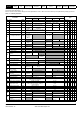
Menu 8 Parameter structure Keypad and display Parameter x.00 Parameter Advanced parameter description format descriptions Macros Serial comms protocol Electronic nameplate Performance RFC mode Open-loop, closed-loop vector and servo Table 5-7 I/O state Terminal + type Invert Pr Source / destination Output select Pr Default Pr Default Pr Default T24 input / output 1 Pr 8.01 Pr 8.11 0 Pr 8.21 Pr 10.03 - Zero speed Pr 8.31 1 T25 input / output 2 Pr 8.02 Pr 8.12 0 Pr 8.
Parameter structure Keypad and display 8.10 Drive modes Coding Parameter Parameter Advanced parameter x.
Menu 8 Parameter structure Keypad and display Parameter x.00 Parameter Advanced parameter description format descriptions 8.21 T24 digital I/O 1 source/destination 8.22 T25 digital I/O 2 source/destination 8.23 T26 digital I/O 3 source/destination 8.24 T27 digital input 4 destination 8.25 T28 digital input 5 destination 8.
Parameter structure Keypad and display Parameter Parameter Advanced parameter x.00 description format descriptions 8.31 T24 digital I/O 1 output select 8.32 T25 digital I/O 2 output select 8.
Parameter structure Menu 9 5.11 Keypad and display Parameter Parameter Advanced parameter x.00 description format descriptions Macros Serial comms protocol Electronic nameplate Performance RFC mode Menu 9: Programmable logic, motorized pot and binary sum Figure 5-16 Menu 9 logic diagram: Programmable logic Any bit parameter Function-1 input-1 invert 9.05 Function-1 output indicator ??.?? Function-1 output invert ??.?? x(-1) 9.04 Any bit parameter 9.10 9.
Parameter structure Figure 5-17 Keypad and display Parameter Parameter Advanced parameter x.00 description format descriptions Macros Serial comms protocol Electronic nameplate Performance RFC mode Menu 9 Menu 9 logic diagram: Motorized pot and binary sum Motorized pot. bipolar select Motorized pot. rate Motorized pot. output indicator 9.22 9.23 Motorized pot. destination parameter 9.03 9.25 Motorized pot. up Any unprotected variable parameter 9.26 ??.?? M 9.24 Motorized pot.
Menu 9 Parameter structure Keypad and display Parameter Parameter Advanced parameter x.00 description format descriptions 9.01 Logic function 1 output 9.02 Logic function 2 output Drive modes Coding Update rate 9.
Parameter structure Keypad and display Parameter Parameter Advanced parameter x.00 description format descriptions 9.07 Logic function 1 source 2 invert 9.17 Logic function 2 source 2 invert Drive modes Coding Bit SP FI DE Txt VM DP ND RA NC 4ms x number of menu 9 or 12 functions active read 9.08 Logic function 1 output invert 9.
Parameter structure Menu 9 Keypad and display Parameter Parameter Advanced parameter x.00 description format descriptions 9.10 Logic function 1 destination 9.20 Logic function 2 destination Drive modes SP FI DE Txt VM DP 1 ND RA NC NV 2 PT 1 Range Open-loop, Closed-loop vector, Servo, Regen Pr 0.00 to Pr 21.51 Default Open-loop, Closed-loop vector, Servo, Regen Pr 0.00 Update rate Read on reset 9.
Parameter structure Keypad and display 9.24 Drive modes Coding Parameter Parameter Advanced parameter x.00 description format descriptions Serial comms protocol Macros Electronic nameplate Performance RFC mode Menu 9 Motorized pot scale factor Open-loop, Closed-loop vector, Servo, Regen Bit SP FI DE Txt VM DP ND RA NC NV PT 3 US RW BU 1 Range Open-loop, Closed-loop vector, Servo, Regen 0.000 to 4.000 Default Open-loop, Closed-loop vector, Servo, Regen 1.
Menu 9 9.29 Drive modes Coding Parameter structure Keypad and display Parameter Parameter Advanced parameter x.
Parameter structure Keypad and display 9.34 Drive modes Coding Parameter Parameter Advanced parameter x.
Parameter structure Menu 10 5.12 Keypad and display Parameter x.00 Parameter Advanced parameter description format descriptions Macros Serial comms protocol Electronic nameplate Performance RFC mode Menu 10: Status and trips 10.01 Drive modes Coding Update rate Drive ok Open-loop, Closed-loop vector, Servo, Regen Bit SP FI DE Txt VM DP 1 ND RA 1 NC NV 1 PT US RW BU PS 1 Background write Indicates the drive is not in the trip state. If Pr 10.
Parameter structure Keypad and display 10.07 Drive modes Coding Update rate Parameter Parameter Advanced parameter x.00 description format descriptions Serial comms protocol Macros Electronic nameplate Performance RFC mode Menu 10 Above set speed Open-loop, Closed-loop vector, Servo Bit SP FI DE Txt VM DP 1 ND RA 1 NC NV 1 PT US RW BU PS US RW BU PS 1 Background write These flags are set by the speed detector in menu 3. See Pr 3.06, Pr 3.07 on page 59 and Pr 3.09 on page 60.
Menu 10 10.13 Drive modes Coding Update rate Parameter structure Keypad and display Parameter x.00 Parameter Advanced parameter description format descriptions Macros Serial comms protocol Electronic nameplate Performance RFC mode Direction commanded Open-loop, Closed-loop vector, Servo Bit SP FI DE Txt VM DP 1 ND RA 1 NC NV 1 PT US RW BU PS 1 Background write This parameter is one if the pre-ramp reference (Pr 1.
Parameter structure Keypad and display 10.19 Parameter Parameter Advanced parameter x.00 description format descriptions Serial comms protocol Macros Electronic nameplate Performance RFC mode Menu 10 Drive warning Drive modes Open-loop, Closed-loop vector, Servo, Regen Bit Coding SP FI DE Txt VM DP 1 Update rate ND RA 1 NC NV 1 PT US RW BU PS 1 Background write Indicates that one of the drive alarms is active, i.e. Pr 10.19 = Pr 10.12 OR Pr 10.17 OR Pr 10.18. 10.
Menu 10 Parameter structure Keypad and display Parameter x.00 Parameter Advanced parameter description format descriptions Trip C.Chg 179 C.cPr 188 C.dAt 183 C.Err 182 C.
Parameter structure Keypad and display Parameter Parameter Advanced parameter x.00 description format descriptions Macros Trip C.rtg Serial comms protocol Electronic nameplate Performance RFC mode Menu 10 Diagnosis SMARTCARD trip: The voltage and/or current rating of the source and destination drives are different Drive rating dependent parameters (parameters with the RA coding) are likely to have different values and ranges with drives of different voltage and current ratings.
Menu 10 Parameter structure Keypad and display Parameter x.00 Parameter Advanced parameter description format descriptions Trip EnC6 194 EnC7 195 EnC8 Macros Serial comms protocol Electronic nameplate Performance RFC mode Diagnosis Drive encoder trip: Encoder has indicated an error Replace feedback device With SSI encoders, check the wiring and encoder supply setting Drive encoder trip: Initialisation failed Re-set the drive Check the correct encoder type is entered into Pr 3.
Parameter structure Keypad and display Parameter Parameter Advanced parameter x.00 description format descriptions Trip Macros Serial comms protocol Performance RFC mode Menu 10 Diagnosis Et External trip from input on terminal 31 6 Check terminal 31 signal Check value of Pr 10.32 Enter 12001 in Pr xx.00 and check for parameter controlling Pr 10.32 Ensure Pr 10.32 or Pr 10.
Menu 10 Parameter structure Keypad and display Parameter x.00 Parameter Advanced parameter description format descriptions Trip HF25 225 HF26 226 HF27 227 HF28 228 HF29 229 HF30 230 HF31 231 HF32 232 It.AC 20 It.br 19 L.SYnC 39 O.CtL 23 O.ht1 21 O.
Parameter structure Keypad and display Parameter Parameter Advanced parameter x.00 description format descriptions Trip Oht2.P 105 O.ht3 27 Oht4.P 102 OI.AC 3 OIAC.P 104 OI.br 4 OIbr.P 103 OIdC.
Menu 10 Parameter structure Keypad and display Parameter x.00 Parameter Advanced parameter description format descriptions Trip O.Ld1 26 O.SPd 7 OV 2 OV.
Parameter structure Keypad and display Parameter Parameter Advanced parameter x.00 description format descriptions Trip PS.P 108 PSAVE.Er Macros Serial comms protocol Electronic nameplate Performance RFC mode Menu 10 Diagnosis Power module power supply fail Remove any Solutions Modules and reset Hardware fault - return drive to supplier Power down save parameters in the EEPROM are corrupt 37 Indicates that the power was removed when power down save parameters were being saved.
Menu 10 Parameter structure Keypad and display Parameter x.00 Parameter Advanced parameter description format descriptions Trip SLX.Er Macros Serial comms protocol Electronic nameplate Performance RFC mode Diagnosis Solutions Module slot X trip: Solutions Module in slot X has detected a fault Feedback module category Check value in Pr 15/16/17.50. The following table lists the possible error codes for the SM-Universal Encoder Plus, SM-Encoder Output Plus, SM-Encoder Plus and SM-Resolver.
Parameter structure Keypad and display Parameter Parameter Advanced parameter x.00 description format descriptions Trip SLX.Er Macros Serial comms protocol Electronic nameplate Performance RFC mode Menu 10 Diagnosis Solutions Module slot X trip: Solutions Module in slot X has detected a fault Automation (Applications) module category Check value in Pr 15/16/17.50. The following table lists the possible error codes for the SM-Applications and SM-Applications Lite.
Menu 10 Parameter structure Keypad and display Parameter x.00 Parameter Advanced parameter description format descriptions Trip SLX.Er Macros Serial comms protocol Electronic nameplate Performance RFC mode Diagnosis Solutions Module slot X trip: Solutions Module in slot X has detected a fault Automation (I/O Expansion) module category Check value in Pr 15/16/17.50.
Parameter structure Keypad and display Parameter Parameter Advanced parameter x.00 description format descriptions Trip SLX.Er Macros Serial comms protocol Electronic nameplate Performance RFC mode Menu 10 Diagnosis Solutions Module slot X trip: Solutions Module in slot X has detected a fault SLM module category Check value in Pr 15/16/17.50. The following table lists the possible error codes for the SM-SLM. See the Diagnostics section in the SM-SLM User Guide for more information.
Menu 10 Parameter structure Keypad and display Parameter x.00 Parameter Advanced parameter description format descriptions Trip t216 216 Check motor temperature Check thermistor continuity Set Pr 7.15 = VOLt and reset the drive to disable this function thS Motor thermistor short circuit 25 Check motor thermistor wiring Replace motor / motor thermistor Set Pr 7.15 = VOLt and reset the drive to disable this function 11 tunE2* 12 tunE3* 13 tunE4* 14 tunE5* 15 tunE6* 16 tunE7* 17 Unid.
Parameter structure Keypad and display Parameter Parameter Advanced parameter x.
Menu 10 Parameter structure Keypad and display Parameter x.00 Parameter Advanced parameter description format descriptions Macros Serial comms protocol Electronic nameplate Performance RFC mode Trips can be grouped into the following categories. It should be noted that a trip can only occur when the drive is not tripped, or is already tripped but with a trip with a lower priority number.
Parameter structure Table 5-11 Keypad and display Parameter Parameter Advanced parameter x.
Parameter structure Menu 10 Keypad and display Parameter x.00 Parameter Advanced parameter description format descriptions Macros Serial comms protocol Electronic nameplate Performance RFC mode For SP0xxx, SP1xxx and SP2xxx drives the default value is a suitable value for standard braking resistors that can be mounted within the drive heatsink as given in the table below. For larger drives the default is 0.00. Parameter default Drive voltage rating SP0xxx 0.06s 0.
Parameter structure Keypad and display Parameter Parameter Advanced parameter x.00 description format descriptions Macros Serial comms protocol Electronic nameplate Performance RFC mode Menu 10 The braking resistor temperature is modelled by the drive as shown below. The temperature rises in proportion to the power flowing into the resistor and falls in proportion to the difference between the resistor temperature and ambient.
Menu 10 10.32 Drive modes Coding Parameter structure Keypad and display Parameter x.00 Parameter Advanced parameter description format descriptions Macros Serial comms protocol Electronic nameplate Performance RFC mode External trip Open-loop, Closed-loop vector, Servo, Regen Bit SP FI DE Txt VM DP ND RA 1 NC NV PT US RW BU 1 Default Open-loop, Closed-loop vector, Servo, Regen Update rate Background read PS 1 0 If this flag is set to one then the drive will trip (Et).
Parameter structure Keypad and display 10.37 Parameter Parameter Advanced parameter x.
Parameter structure Menu 10 10.39 Keypad and display Parameter x.00 Parameter Advanced parameter description format descriptions Macros Serial comms protocol Electronic nameplate Performance RFC mode Braking energy overload accumulator Drive modes Open-loop, Closed-loop vector, Servo, Regen Bit Coding SP FI DE Txt VM DP ND 1 Range Open-loop, Closed-loop vector, Servo, Regen Update rate Background read RA NC 1 NV 1 PT US RW BU 1 PS 1 0.0 to 100.
Parameter structure Keypad and display Parameter Parameter Advanced parameter x.00 description format descriptions 10.43 Module number for trip 1, or Trip 1 time 10.44 Module number for trip 2, or Trip 2 time 10.45 Module number for trip 3, or Trip 3 time 10.46 Module number for trip 4, or Trip 4 time 10.47 Module number for trip 5, or Trip 5 time 10.48 Module number for trip 6, or Trip 6 time 10.49 Module number for trip 7, or Trip 7 time 10.
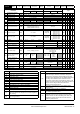
Parameter structure Menu 11 5.13 Keypad and display Parameter Parameter Advanced parameter x.00 description format descriptions Macros Serial comms protocol Electronic nameplate Performance RFC mode Menu 11: General drive set-up 11.01 Parameter 0.11 set-up 11.02 Parameter 0.12 set-up 11.03 Parameter 0.13 set-up 11.04 Parameter 0.14 set-up 11.05 Parameter 0.15 set-up 11.06 Parameter 0.16 set-up 11.07 Parameter 0.17 set-up 11.08 Parameter 0.18 set-up 11.09 Parameter 0.
Parameter structure Keypad and display 11.21 Drive modes Coding Parameter Parameter Advanced parameter x.00 description format descriptions Serial comms protocol Macros Electronic nameplate Performance RFC mode Menu 11 Parameter 0.30 scaling Open-loop, Closed-loop vector, Servo, Regen Bit SP FI DE Txt VM DP ND RA NC NV PT 3 US RW BU 1 Range Open-loop, Closed-loop vector, Servo, Regen 0.000 to 9.999 Default Open-loop, Closed-loop vector, Servo, Regen 1.
Parameter structure Menu 11 Keypad and display Parameter Parameter Advanced parameter x.00 description format descriptions Parameter value String Comms mode 0 AnSI ANSIx3.28 protocol Macros 1 rtU Modbus RTU protocol 2 Lcd Modbus RTU protocol, but only with an LCD keypad Serial comms protocol Electronic nameplate Performance RFC mode ANSIx3.28 protocol Full details of the CT implementation of ANSIx3.28 are given in Chapter 7 Serial communications protocol on page 402.
Parameter structure Keypad and display 11.26 Drive modes Coding Parameter Parameter Advanced parameter x.
Parameter structure Menu 11 11.30 Drive modes Parameter Parameter Advanced parameter x.
Parameter structure Keypad and display 11.34 Drive modes Coding Parameter Parameter Advanced parameter x.
Menu 11 Parameter structure Keypad and display Parameter Parameter Advanced parameter x.
Parameter structure Keypad and display Parameter Parameter Advanced parameter x.00 description format descriptions Macros Serial comms protocol Electronic nameplate Performance RFC mode Menu 11 When the data is transferred back to a drive, using 6yyy in Pr x.00, it is transferred to the drive RAM and then to the drive EEPROM. A parameter save is not required to retain the data after power-down. Onboard Application Lite user program data blocks This type of data block is created when 5xxx in Pr x.
Parameter structure Menu 11 Keypad and display Drive modes Parameter Parameter Advanced parameter x.00 description format descriptions Gains Macros Serial comms protocol Electronic nameplate Performance RFC mode Scaling applied Closed-loop vector Servo Speed controller gains Closed-loop vector Servo Regen Current controller gains x Destination Pr 11.32 / Source Pr 11.32 x Source Pr 11.32 / Destination Pr 11.
Parameter structure Keypad and display Parameter Parameter Advanced parameter x.00 description format descriptions Serial comms protocol Macros Electronic nameplate Performance RFC mode Menu 11 Gives the type/mode of the data block selected with Pr 11.37 as shown below. Pr 11.38 String Type/mode 0 FrEE Value when Pr 11.37 = 0 1 3C.SE Commander SE mode parameter file (not used) 2 3OPEn.LP Open-loop mode parameter file 3 3CL.
Menu 11 11.42 Drive modes Coding Parameter structure Keypad and display Parameter Parameter Advanced parameter x.
Parameter structure Keypad and display 11.43 Drive modes Serial comms protocol Macros Electronic nameplate Performance RFC mode Menu 11 Load defaults Open-loop, Closed-loop vector, Servo, Regen Bit Coding Parameter Parameter Advanced parameter x.
Parameter structure Menu 11 11.47 Keypad and display Parameter Parameter Advanced parameter x.
Parameter structure Keypad and display 11.50 Drive modes Coding Parameter Parameter Advanced parameter x.
Parameter structure Menu 12 5.14 Keypad and display Parameter x.
Parameter structure Figure 5-19 Keypad and display Parameter Parameter Advanced parameter x.00 description format descriptions Serial comms protocol Macros Electronic nameplate Performance RFC mode Menu 12 Menu 12 Logic diagram (continued) Variable Selector 1 Any variable parameter Variable selector 1 output indicator Variable selector 1 input 1 scaling ??.?? Variable selector 1 output destination 12.13 12.12 ??.?? Variable selector 1 input 1 source 12.08 Any variable parameter 12.
Menu 12 Parameter structure Keypad and display Parameter x.00 12.04 Threshold detector 1 level 12.24 Threshold detector 2 level Drive modes Coding Parameter Advanced parameter description format descriptions Bit SP FI DE Txt VM DP ND RA NC NV Default Open-loop, Closed-loop vector, Servo, Regen 0.00 Update rate 4ms x number of menu 9 or 12 functions active read 12.05 Threshold detector 1 hysteresis 12.
Parameter structure Keypad and display Parameter Parameter Advanced parameter x.00 description format descriptions 12.08 Variable selector 1 source 1 12.28 Variable selector 2 source 1 Drive modes Coding Bit SP FI DE Txt VM DP ND RA NC NV 2 Pr 0.00 to Pr 21.51 Default Open-loop, Closed-loop vector, Servo, Regen Pr 0.00 Update rate Read on reset 12.09 Variable selector 1 source 2 12.29 Variable selector 2 source 2 Bit SP FI DE Txt VM DP ND RA NC NV 2 Pr 0.00 to Pr 21.
Menu 12 Parameter structure Keypad and display Parameter x.00 Parameter Advanced parameter description format descriptions 12.13 Variable selector 1 source 1 scaling 12.33 Variable selector 2 source 1 scaling Drive modes Coding Bit SP FI DE Txt VM DP ND RA NC Default Open-loop, Closed-loop vector, Servo, Regen 1.000 Update rate 4ms x number of menu 9 or 12 functions active read 12.14 Variable selector 1 source 2 scaling 12.
Parameter structure Keypad and display Parameter Parameter Advanced parameter x.00 description format descriptions Mode value Action 0 Select input 1 output = input1 1 Select input 2 output = input2 2 Add 3 Subtract output = input1 - input 2 4 Multiply output = (input1 x input2) / 100.0 Macros Serial comms protocol Electronic nameplate Performance RFC mode Menu 12 Result output = input1 + input2 5 Divide 6 Time constant output = (input1 x 100.
Parameter structure Menu 12 Input reference Keypad and display SM-Universal Encoder Plus module Output reference Parameter x.00 Parameter Advanced parameter description format descriptions Source Pr 12.08 =Pr x.05 Variable selector in sectional control mode Macros Destination Pr 12.11 = Pr 13.21 Serial comms protocol Electronic nameplate Performance RFC mode Menu 13 position controller Reference source Pr 13.04 =Local(4) Ignore local reference turns Pr 13.
Parameter structure Keypad and display 12.41 Drive modes Parameter Parameter Advanced parameter x.
Parameter structure Menu 12 Keypad and display Parameter x.00 Parameter Advanced parameter description format descriptions Macros Serial comms protocol Electronic nameplate Performance RFC mode Open-loop WARNING The brake control functions are provided to allow well co-ordinated operation of an external brake with the drive. While both hardware and software are designed to high standards of quality and robustness, they are not intended for use as safety functions, i.e.
Parameter structure Keypad and display 12.42 Drive modes Coding Parameter Parameter Advanced parameter x.00 description format descriptions Macros Serial comms protocol Bit SP FI DE Txt VM DP ND RA NC NV PT US RW BU 1 0 to 200 % Default Open-loop 50 Update rate Background read Coding RFC mode Menu 12 Open-loop Open-loop Drive modes Performance Upper current threshold Range 12.
Menu 12 12.46 Drive modes Coding Parameter structure Keypad and display Parameter x.00 Parameter Advanced parameter description format descriptions Macros Serial comms protocol Electronic nameplate Performance RFC mode Pre-brake release delay Open-loop Bit SP FI DE Txt VM DP ND RA NC NV PT 1 US RW BU 1 Range Open-loop 0.0 to 25.0 s Default Open-loop 1.
Parameter structure Keypad and display Parameter Parameter Advanced parameter x.00 description format descriptions Macros Serial comms protocol Electronic nameplate Performance RFC mode Menu 12 Closed loop vector and Servo WARNING The brake control functions are provided to allow well co-ordinated operation of an external brake with the drive. While both hardware and software are designed to high standards of quality and robustness, they are not intended for use as safety functions, i.e.
Menu 12 12.43 Drive modes Coding Parameter structure Keypad and display Parameter x.
Parameter structure Keypad and display 12.49 Drive modes Coding Parameter Parameter Advanced parameter x.
Menu 13 5.15 Parameter structure Keypad and display Parameter Parameter Advanced parameter x.00 description format descriptions Macros Serial comms protocol Electronic nameplate Performance RFC mode Menu 13: Position control Menu 13 provides a position control system for the drive in open-loop mode and closed-loop modes (closed-loop vector and servo). The position reference can be taken from the drive encoder, from a position feedback module or from a local reference defined in this menu.
Parameter structure Keypad and display Parameter Parameter Advanced parameter x.00 description format descriptions Unidrive SP Advanced User Guide Issue Number: 10 Macros Serial comms protocol Electronic nameplate Performance RFC mode Menu 13 233 www.controltechniques.
Menu 13 Figure 5-24 Parameter structure Keypad and display Parameter Parameter Advanced parameter x.00 description format descriptions Serial comms protocol Macros Electronic nameplate Performance RFC mode Menu 13 Open-loop logic diagram Relative jog reverse Relative jog enable 13.19 13.18 Relative jog reference Position control reference position 13.17 0 Drive Encoder Slot 1 3.28 3.29 x(-1) Position controller reference source 3.30 15.04 15.05 15.06 Slot 2 0 1 2 3 4 16.04 16.
Parameter structure Keypad and display Parameter Parameter Advanced parameter x.00 description format descriptions Macros Frequency/speed reference selected Serial comms protocol Electronic nameplate Performance Pre-ramp reference Menu 2 Ramp Control 1.03 1 Velocity feedforward 1.39 1.40 Menu 13 Post-ramp reference 0 1.01 RFC mode 2.01 Velocity feed -forward select Position controller mode* 13.10 = 1or 2 13.
Menu 13 Figure 5-25 Parameter structure Keypad and display Parameter Parameter Advanced parameter x.00 description format descriptions Macros Serial comms protocol Electronic nameplate Performance RFC mode Menu 13 Closed-loop logic diagram Relative jog reverse Relative jog enable 13.19 13.18 Relative jog reference Position control reference position 13.17 0 Drive Encoder Slot 1 3.28 3.29 x(-1) Position controller reference source 3.30 15.04 15.05 15.06 Slot 2 0 1 2 3 4 16.04 16.
Parameter structure Keypad and display Parameter Parameter Advanced parameter x.00 description format descriptions Macros Serial comms protocol Electronic nameplate Pre-ramp reference Frequency/speed reference 1.01 selected 1.03 Performance RFC mode Post-ramp reference Menu 2 Ramp Control Final speed reference + 2.01 Menu 13 3.01 + Velocity feedforward Position controller mode** 13.10 13.10 = 5 or 6 1.39 1.40 Velocity feed -forward select Hard speed reference selector 13.
Menu 13 13.01 Drive modes Coding Parameter structure Keypad and display Parameter Parameter Advanced parameter x.00 description format descriptions Bit SP FI DE Txt VM DP 4ms write Bit SP FI DE Txt RA NC NV 1 PT US RW BU PS US RW BU PS US RW BU PS 1 -32,768 to 32,767 VM DP ND RA 1 Open-loop, Closed-loop vector, Servo 4ms write Coding RFC mode Open-loop, Closed-loop vector, Servo Update rate Drive modes Performance Position error Range 13.
Parameter structure Keypad and display 13.06 Drive modes Coding Parameter Parameter Advanced parameter x.00 description format descriptions Bit SP FI DE Txt VM DP ND RA NC NV Menu 13 PS 1 Ratio numerator Open-loop, Closed-loop vector, Servo Bit SP FI DE Txt VM DP ND RA NC NV PT US RW BU 3 1 Open-loop, Closed-loop vector, Servo 0.000 to 4.000 Default Open-loop, Closed-loop vector, Servo 1.000 Update rate Background read Coding RFC mode 0 Range 13.
Parameter structure Menu 13 Keypad and display Parameter value Parameter Parameter Advanced parameter x.
Parameter structure Keypad and display Parameter Parameter Advanced parameter x.00 description format descriptions Serial comms protocol Macros Electronic nameplate Performance RFC mode Menu 13 When orientating from a stop command the drive goes through the following sequence: 1. The motor is decelerated or accelerated to the speed limit programmed in Pr 13.12, using ramps if these are enabled, in the direction the motor was previously running. 2.
Menu 13 13.14 Drive modes Coding Parameter structure Keypad and display Parameter Parameter Advanced parameter x.00 description format descriptions Bit SP FI DE Txt VM DP ND RA NC Default Closed-loop vector, Servo 256 Update rate Background read Update rate NV PT US RW BU 1 0 to 4,096 Coding Electronic nameplate Performance RFC mode Closed-loop vector, Servo Closed-loop vector, Servo 13.
Parameter structure Keypad and display 13.19 Drive modes Coding Parameter Parameter Advanced parameter x.
Menu 13 Parameter structure Keypad and display Parameter Parameter Advanced parameter x.00 description format descriptions Macros Serial comms protocol Electronic nameplate Performance RFC mode is used. This allows all three parts of the local reference position to be changed without data skew problems. 13.
Parameter structure Keypad and display Parameter Parameter Advanced parameter x.00 description format descriptions Unidrive SP Advanced User Guide Issue Number: 10 Macros Serial comms protocol Electronic nameplate Performance RFC mode Menu 14 245 www.controltechniques.
Parameter structure Menu 14 5.16 Keypad and display Parameter Parameter Advanced parameter x.00 description format descriptions Macros Serial comms protocol Electronic nameplate Performance RFC mode Menu 14: User PID controller This menu contains a PID controller which has programmable reference and feedback inputs, programmable enable bit, reference slew rate limiting, variable clamp levels and programmable destination. The sample rate of the PID controller is 4ms.
Parameter structure Keypad and display Parameter Parameter Advanced parameter x.00 description format descriptions PID hold integrator enable 14.17 Macros 14.13 PID output high limit 14.14 PID output low limit 14.18 PID symmetrical limits enable 14.10 PID proportional gain 14.11 PID integral gain Serial comms protocol PID controller output 14.01 Electronic nameplate Performance RFC mode Menu 14 PID output destination parameter* PID output scale factor 14.15 14.
Menu 14 14.01 Drive modes Coding Parameter structure Keypad and display Parameter Parameter Advanced parameter x.00 description format descriptions Macros Serial comms protocol Electronic nameplate Performance RFC mode PID output Open-loop, Closed-loop vector, Servo, Regen Bit SP FI DE Txt VM DP 2 Range Open-loop, Closed-loop vector, Servo, Regen Update rate 4ms write ND RA 1 NC NV 1 PT US RW BU PS 1 ±100.
Parameter structure Keypad and display 14.08 Drive modes Coding Parameter Parameter Advanced parameter x.00 description format descriptions Bit SP FI DE Txt VM DP ND RA NC NV PT 1 US RW BU 1 Update rate 4ms read Coding Performance RFC mode Menu 14 Open-loop, Closed-loop vector, Servo, Regen Open-loop, Closed-loop vector, Servo, Regen 14.
Menu 14 14.13 Drive modes Coding Parameter structure Keypad and display Parameter Parameter Advanced parameter x.00 description format descriptions Bit SP FI DE Txt VM DP ND RA NC NV PT 2 US RW BU 1 0.00 to 100.00 % Default Open-loop, Closed-loop vector, Servo, Regen 100.00 Update rate Background read Coding Electronic nameplate Performance RFC mode Open-loop, Closed-loop vector, Servo, Regen Open-loop, Closed-loop vector, Servo, Regen 14.
Parameter structure Keypad and display 14.18 Drive modes Coding Parameter Parameter Advanced parameter x.00 description format descriptions Serial comms protocol Macros Electronic nameplate Performance RFC mode Menu 14 PID symmetrical limit enable Open-loop, Closed-loop vector, Servo, Regen Bit SP FI DE Txt VM DP ND RA NC NV PT 1 US RW BU 1 Default Open-loop, Closed-loop vector, Servo, Regen Update rate Background read PS 1 0 See Pr 14.13 and Pr 14.14. 14.
Menus 15 to 17 5.17 Parameter structure Keypad and display Parameter Parameter Advanced parameter x.00 description format descriptions Macros Serial comms protocol Electronic nameplate Performance RFC mode Menus 15, 16 and 17: Solutions Module slots Pr x.00 and Pr x.01 are always present in menus 15, 16 and 17. Pr x.01 indicates which type of module is present (0 = no module installed).
Parameter structure 5.17.1 Keypad and display Parameter Parameter Advanced parameter x.00 description format descriptions Macros Serial comms protocol Electronic nameplate Performance RFC mode Menus 15 to 17 SM-Uni Enc Pl SM-Universal Encoder Plus The Solutions Module checks for various errors as shown below. Table 5-13 Solutions Module error status values for SM-Universal Encoder Plus Error code Encoders 1 All Ab, Fd, Fr, Ab.SErvo, Fd.SErvo, Fr.SErvo, SC.SErvo SC, SC.HiPEr, SC.EndAt, SSC.
Menus 15 to 17 SM-Uni Enc Pl Parameter structure Keypad and display Parameter Parameter Advanced parameter x.00 description format descriptions Macros Serial comms protocol Electronic nameplate Performance RFC mode Wire-break detection It may be important to detect a break in the connections between the drive and the position feedback device. This feature is provided for most encoder types either directly or indirectly as listed below. Pr x.50 2 2 4, 5 5, 6 Encoders Ab, Fd, Fr, Ab.SErvo, Fd.
Parameter structure Keypad and display Parameter Parameter Advanced parameter x.00 description format descriptions Unidrive SP Advanced User Guide Issue Number: 10 Macros Serial comms protocol Electronic nameplate Performance RFC mode Menus 15 to 17 SM-Uni Enc Pl 255 www.controltechniques.
Menus 15 to 17 SM-Uni Enc Pl Figure 5-27 Parameter structure Keypad and display Parameter Parameter Advanced parameter x.00 description format descriptions Serial comms protocol Macros Electronic nameplate Performance RFC mode SM-Universal Encoder Plus logic diagram Reference / feedback encoder input Parameter Solutions Module 15-way D-type SK1 Error detection x.09 Encoder turns / Linear encoder comms to sinewave ratio x.10 Equivalent lines per rev Single turn comms resolution / x.
Parameter structure Keypad and display Parameter Parameter Advanced parameter x.00 description format descriptions Serial comms protocol Macros Electronic nameplate Performance RFC mode Menus 15 to 17 SM-Uni Enc Pl Speed feedback selector 3.26 Speed feedback selector Motor map 2 21.21 Speed Feedback filter x.19 + 16ms internal filter _ x.03 x.49 Lock position feedback Revolution counter Position x.04 x.05 Fine position Maximum feedback reference (rpm) x.06 x.
Menus 15 to 17 SM-Uni Enc Pl x.01 RO Parameter structure Keypad and display Parameter Parameter Advanced parameter x.00 description format descriptions Macros Serial comms protocol Electronic nameplate Performance RFC mode Solutions Module ID code Uni Ú PT US Ö 0 to 599 Update rate: Write on power-up The menu for the relevant slot appears for the new Solutions Module category with the default parameter values for the new category.
Parameter structure Keypad and display Parameter Parameter Advanced parameter x.00 description format descriptions Macros Serial comms protocol Electronic nameplate Performance RFC mode Menus 15 to 17 SM-Uni Enc Pl Example: A 1024 line digital encoder produces 4096 counts per revolution, and so the position is represented by the bits in the shaded area only.
Menus 15 to 17 SM-Uni Enc Pl Parameter structure Keypad and display Parameter Parameter Advanced parameter x.00 description format descriptions Macros Serial comms protocol Electronic nameplate Performance RFC mode NOTE It should be noted that if the Pr x.19 the Feedback Filter is used where, the speed feedback is provided by either an EndAt or SSI encoder connected directly to the module, it is necessary for the encoder to provide at least 6 bits of turns information.
Parameter structure Keypad and display Parameter Parameter Advanced parameter x.00 description format descriptions Macros Serial comms protocol Electronic nameplate Performance RFC mode Menus 15 to 17 SM-Uni Enc Pl SC.HiPEr, SC.EndAt, SC.SSI and x.16 = 0 (Linear encoder) Pr x.11 must be set up to the total number of bits representing the whole encoder position in the comms message. This parameter is not used with linear SC.
Menus 15 to 17 SM-Uni Enc Pl x.15 RW Ú Parameter structure Keypad and display Parameter Parameter Advanced parameter x.00 description format descriptions Macros Serial comms protocol Electronic nameplate Performance RFC mode Encoder type Uni US Ö 0 to 12 0 Update rate: Background read The following encoders can be connected to the SM-Universal Encoder Plus.
Parameter structure Keypad and display Parameter Parameter Advanced parameter x.00 description format descriptions Macros Serial comms protocol Electronic nameplate Performance RFC mode Menus 15 to 17 SM-Uni Enc Pl . Encoder termination/rotary encoder select/comms only encoder mode x.16 RW Txt Ú US Ö 0 to 2 1 Update rate: Background read Encoder termination select Ab, Fd, Fr, Ab.SErvo, Fd.SErvo, Fr.SErvo.
Menus 15 to 17 SM-Uni Enc Pl x.17 RW Parameter structure Keypad and display Parameter Parameter Advanced parameter x.00 description format descriptions Macros Serial comms protocol Electronic nameplate Performance RFC mode Error detection level Uni US Ú Ö 0 to 15 0 Update rate: Background read Trips can be enabled/disabled using Pr x.
Parameter structure Keypad and display Parameter Parameter Advanced parameter x.00 description format descriptions Macros Serial comms protocol Electronic nameplate Performance RFC mode Menus 15 to 17 SM-Uni Enc Pl Linear EndAt encoders The comms resolution is set to the number of bits required for the whole position within the position data messages from the encoder. The linear encoder comms to sine wave ratio is calculated from the sine wave period and LS comms bit length.
Menus 15 to 17 SM-Uni Enc Pl x.22 RW Parameter structure Keypad and display Parameter Parameter Advanced parameter x.00 description format descriptions Macros Serial comms protocol Electronic nameplate Performance RFC mode Feedback reference scaling Uni Ú US Ö 0.000 to 4.000 1.000 Update rate: Background read The feedback reference scaling is applied as follows: 3000rpm Motor Parameter Example 1 Example 2 Example 3 Example 4 Example 5 Example 6 Pr x.20 Max f/b ref 3000.0 1500.0 6000.0 3000.
Parameter structure Keypad and display x.26 RW Parameter Parameter Advanced parameter x.00 description format descriptions Macros Serial comms protocol Electronic nameplate Performance RFC mode Menus 15 to 17 SM-Uni Enc Pl Encoder simulation ratio denominator Uni Ú US 0.0000 to 3.0000 Ö 1.0000 Update rate: Background read The simulated encoder output (incremental), Ab, Ab.L, Fd, Fd.L can be scaled using the above parameter. x.
Menus 15 to 17 SM-Uni Enc Pl x.31 RO Parameter structure Keypad and display Macros Serial comms protocol Electronic nameplate Performance RFC mode Non-marker reset fine position Uni NC 0 to 65535 (1/232nds of a revolution) Ú Parameter Parameter Advanced parameter x.00 description format descriptions PT Ö Update rate: 4ms write This position is taken from the position feedback device and is not affected by the marker or the freeze inputs. x.
Parameter structure Keypad and display Value in Pr x.38 0 1 2 3 4 5 6 7 Parameter Parameter Advanced parameter x.00 description format descriptions 24V input No Yes No Yes No Yes No Yes 485 input No No Yes Yes No No Yes Yes Macros Serial comms protocol Electronic nameplate Performance RFC mode Menus 15 to 17 SM-Uni Enc Pl Drive/slot bus input No No No No Yes Yes Yes Yes NOTE Modes 4 to 7 are only available with the drive software versions 01.07.00 onwards and issue 4 SM-Universal Encoder Plus.
Menus 15 to 17 SM-Uni Enc Pl x.43 RW Parameter structure Keypad and display Parameter Parameter Advanced parameter x.00 description format descriptions Macros Serial comms protocol Electronic nameplate Performance RFC mode Encoder comms receive register/Cos signal value Uni Ú NC 0 to 65535 Ö 0 Update rate: Background write In SINCOS mode (6) ONLY with no comms or commutation inputs, the internal differential Cos signal is written to this parameter as an unsigned number.
Parameter structure Keypad and display x.47 RW Parameter Parameter Advanced parameter x.00 description format descriptions Macros Serial comms protocol Electronic nameplate Performance RFC mode Menus 15 to 17 SM-Uni Enc Pl SSI output turns Uni Ú US 0 to 16 Ö 16 Update rate: Background read Used to define the simulated encoder output in SSI mode, refer to the SM-Universal Encoder Plus User Guide. x.
Menus 15 to 17 SM-Resolver 5.17.2 Parameter structure Keypad and display Parameter Advanced parameter Parameter description format descriptions x.00 Macros Serial comms protocol Electronic Performance RFC mode nameplate SM-Resolver The Solutions Module checks for various errors as shown below.
Parameter structure Keypad and display Parameter Parameter Advanced parameter x.00 description format descriptions Macros Serial comms protocol Electronic Performance RFC mode nameplate Positional information Key Revolution counter Position x.04 Input terminals 0.XX Read-write (RW) parameter 0.XX Read-only (RO) parameter x.05 Output terminals Resolver selected as drive feedback (Pr 3.
Menus 15 to 17 SM-Resolver Parameter structure Keypad and display Parameter Advanced parameter Parameter description format descriptions x.00 Macros Serial comms protocol Electronic Performance RFC mode nameplate When an SM-Resolver is installed the user parameter menu for the module contains all the parameters for a position feedback category Solutions Module. However, all parameters are not used by this Solutions Module.
Parameter structure Keypad and display Parameter Parameter Advanced parameter x.00 description format descriptions Macros Serial comms protocol Electronic Performance RFC mode nameplate Menus 15 to 17 SM-Resolver Pr x.04 and Pr x.05 give the position with a resolution of 1/216ths of a revolution as a 32 bit number as shown below.
Menus 15 to 17 SM-Resolver x.13 RW Parameter structure Keypad and display Parameter Advanced parameter Parameter description format descriptions x.00 Macros Serial comms protocol Electronic Performance RFC mode nameplate Resolver excitation Uni Ú US Ö 3:1 (0), 2:1 (1 or 2) 3:1 (0) Update rate: Background read The excitation level can be controlled for use with 3:1 ratio resolvers (Pr x.13 = 0), or 2:1 ratio resolvers (Pr x.13 = 1 or 2). x.
Parameter structure Keypad and display x.19 RW Parameter Parameter Advanced parameter x.00 description format descriptions Serial comms protocol Electronic Performance RFC mode nameplate Menus 15 to 17 SM-Resolver Feedback filter Uni Ú Macros US Ö 0 to 5 (0 to 16 ms) 0 Update rate: Background read A sliding window filter may be applied to the feedback.
Menus 15 to 17 SM-Resolver x.30 RO Parameter structure Keypad and display Macros Serial comms protocol Electronic Performance RFC mode nameplate Non-marker reset position Uni NC 16 0 to 65,535 (1/2 ths of a revolution) Ú Parameter Advanced parameter Parameter description format descriptions x.00 PT Ö Update rate: 4ms x number of dumb modules Pr x.29 and Pr x.30 are duplicates of Pr x.04 and Pr x.05 respectively. x.
Parameter structure Keypad and display Parameter Parameter Advanced parameter x.00 description format descriptions Unidrive SP Advanced User Guide Issue Number: 10 Macros Serial comms protocol Electronic Performance RFC mode nameplate Menus 15 to 17 SM-Encoder Pl 279 www.controltechniques.
Menus 15 to 17 SM-Encoder Pl 5.17.3 Parameter structure Keypad and display Parameter Parameter Advanced parameter x.00 description format descriptions Macros Serial comms protocol Electronic nameplate Performance RFC mode SM-Encoder Plus / SM-Encoder Output Plus The Solutions Modules checks for various errors as shown below.
Parameter structure Keypad and display Parameter Parameter Advanced parameter x.00 description format descriptions Feedback filter x.19 Macros Serial comms protocol Electronic Performance RFC mode nameplate Menus 15 to 17 SM-Encoder Pl Speed x.03 x.49 Lock position feedback Revolution counter Position x.04 x.05 Positional information Key Input terminals 0.XX Read-write (RW) parameter Output terminals 0.
Menus 15 to 17 SM-Encoder Pl Figure 5-30 Parameter structure Keypad and display Parameter Parameter Advanced parameter x.00 description format descriptions Serial comms protocol Macros Electronic nameplate Performance RFC mode SM-Encoder Output Plus Encoder logic diagram Non marker position information Solutions Module terminal block Term 1 2 3 4 5 6 7 8 8-Way Revolution counter Position Position feedback initialised Encoder connections A A\ B B\ Z Z\ 0V +V x.29 x.10 x.16 x.15 x.30 x.
Parameter structure Keypad and display Parameter Parameter Advanced parameter x.00 description format descriptions Feedback filter x.19 Serial comms protocol Macros Electronic Performance RFC mode nameplate Menus 15 to 17 SM-Encoder Pl Speed x.03 x.49 Lock position feedback Revolution counter Position x.04 x.05 Positional information Key Input terminals 0.XX Read-write (RW) parameter Output terminals 0.
Menus 15 to 17 SM-Encoder Pl Parameter structure Keypad and display Parameter Parameter Advanced parameter x.00 description format descriptions Macros Serial comms protocol Electronic nameplate Performance RFC mode The update time for some functions are affected by the number of dumb Solutions Modules installed to the drive. The update time for these functions is the sum of the update times for all dumb Solutions Modules installed to the drive, called the combined update time.
Parameter structure Keypad and display x.07 RW Parameter Parameter Advanced parameter x.00 description format descriptions Macros Serial comms protocol Electronic Performance RFC mode nameplate Menus 15 to 17 SM-Encoder Pl Marker position reset disable Bit Ú US OFF (0) or On (1) Ö OFF (0) Update rate: Background read x.
Menus 15 to 17 SM-Encoder Pl x.19 RW Parameter structure Keypad and display Parameter Parameter Advanced parameter x.00 description format descriptions Macros Serial comms protocol Electronic nameplate Performance RFC mode Feedback filter Uni Ú US 0 to 5 (0 to 16 ms) Ö 0 Update rate: Background read A sliding window filter may be applied to the feedback.
Parameter structure Keypad and display x.28 Parameter Parameter Advanced parameter x.00 description format descriptions Macros Serial comms protocol Electronic Performance RFC mode nameplate Menus 15 to 17 SM-Encoder Pl Encoder simulation mode RW Txt Ú 0 to 7 US 0 Update rate: Background read Pr x.28 selects the format of the encoder simulation output as shown in the table below. Pr x.
Menus 15 to 17 SM-Encoder Pl Parameter structure x.39 Freeze flag RW Keypad and display Bit Ú Parameter Parameter Advanced parameter x.00 description format descriptions Macros Serial comms protocol Electronic nameplate Performance RFC mode NC OFF (0) or On (1) Ö OFF (0) Update rate: 4ms x number of dumb modules This Solutions Module does not have its own freeze input, therefore the freeze input must come from a SM-Applications or SM-Universal Encoder Plus.
Parameter structure 5.17.4 Keypad and display Parameter Parameter Advanced parameter x.00 description format descriptions Macros Serial comms protocol Electronic nameplate Performance RFC mode Menus 15 to 17 SM-I/O Plus SM-IO Plus Table 5-16 Solutions Module error status values for the SM-I/O Plus Error code Reason for fault 0 1 74 No errors Digital output short circuit Module over-temperature Figure 5-31 SM I/O Plus Digital Input/Output logic diagram 1 T2 digital I/O 1 state X.
Menus 15 to 17 SM-I/O Plus Figure 5-32 Parameter structure Keypad and display Parameter Parameter Advanced parameter x.00 description format descriptions Macros Serial comms protocol Electronic nameplate Performance RFC mode SM I/O Plus Digital Input/Output logic diagram 2 T6 digital input 4 state indicator X.04 T6 digital input 4 invert T6 digital input 4 destination X.14 X.24 T6 digital input 4 Any unprotected bit parameter ??.?? X.
Parameter structure Keypad and display Parameter Parameter Advanced parameter x.00 description format descriptions Pr x.29=0 (negative logic) Pr x.
Menus 15 to 17 SM-I/O Plus Figure 5-33 Parameter structure Keypad and display Parameter Parameter Advanced parameter x.00 description format descriptions Serial comms protocol Macros Electronic nameplate Performance RFC mode SM-I/O Plus Analog Input / Output logic diagram T9 Analog input 1 T9 Analog input 1 destination X.40 X.43 T9 Analog input 1 Any unprotected variable parameter ??.?? X.41 T9 Analog input 1 scaling ??.?? x(-1) X.
Parameter structure Keypad and display Parameter Parameter Advanced parameter x.00 description format descriptions Macros Serial comms protocol Electronic nameplate Performance RFC mode Menus 15 to 17 SM-I/O Plus Parameter update times The SM-I/O Plus Solutions Module is a dumb Solutions Module and is controlled directly by the drive's main processor. The update time for some functions are affected by the number of dumb Solutions Modules installed to the drive.
Menus 15 to 17 SM-I/O Plus x.20 RO Parameter structure Keypad and display Parameter Parameter Advanced parameter x.00 description format descriptions Macros Serial comms protocol Electronic nameplate Performance RFC mode Digital I/O read word Uni NC Ú 0 to 511 PT US Ö Update rate: 8ms x number of dumb modules This word is used to determine the status of the digital I/O by reading one parameter. The bits in this word reflect the state of Pr x.03 to Pr x.10.
Parameter structure Keypad and display x.40 RO Parameter Parameter Advanced parameter x.00 description format descriptions Macros Serial comms protocol Electronic nameplate Performance RFC mode Menus 15 to 17 SM-I/O Plus Analog input 1 Bi NC ±100.0% Ú PT Ö Update rate: 8ms x number of dumb modules x.41 RW Analog input 1 scaling Uni Ú US 0 to 4.000 Ö 1.000 Update rate: Background read x.
Menus 15 to 17 SM-I/O Plus x.50 RO Ú Parameter structure Keypad and display Parameter Parameter Advanced parameter x.00 description format descriptions Macros Serial comms protocol Electronic nameplate Performance RFC mode Solutions Module error status Uni NC 0 to 255 PT Ö Update rate: Background read The error status is provided so that the only one option error trip is required for each Solutions Module slot.
Parameter structure 5.17.5 Keypad and display Parameter Parameter Advanced parameter x.
Menus 15 to 17 SM-I/O Lt Tmr Parameter structure Keypad and display Parameter Parameter Advanced parameter x.00 description format descriptions Macros Serial comms protocol Electronic nameplate Performance RFC mode Figure 5-35 SM-I/O Lite & SM-I/O Timer analog I/O logic diagram Destination Invert T2 Analog Input 1 x.43 x.42 Level Scaling Mode x.38 x.40 0.00 x.41 Current mode and protection x(-1) 21.51 Default destination Pr 0.00 x.03 200R 0V Current loop loss indicator Source x.
Parameter structure x.01 RO Keypad and display Parameter Parameter Advanced parameter x.00 description format descriptions Macros Serial comms protocol Electronic nameplate Performance RFC mode Menus 15 to 17 SM-I/O Lt Tmr Solutions Module ID code Uni PT Ú 0 to 599 US Ö Update rate: Write on power-up The menu for the relevant slot appears for the new Solutions Module category with the default parameter values for the new category.
Menus 15 to 17 SM-I/O Lt Tmr Parameter structure Keypad and display Parameter Parameter Advanced parameter x.00 description format descriptions x.14 Terminal T5 digital input 1 invert x.15 Terminal T6 digital input 2 invert x.
Parameter structure Keypad and display x.27 RW Ú Parameter Parameter Advanced parameter x.00 description format descriptions Macros Serial comms protocol Electronic nameplate Performance RFC mode Menus 15 to 17 SM-I/O Lt Tmr Terminal T21 / T23 relay/ source Uni DE Pr 0.00 to Pr 21.51 PT Ö US Pr 0.00 Update rate: Read on drive reset This parameter defines the parameter to be represented by the status relay. Only unprotected parameters can be selected as a source for the relay output.
Menus 15 to 17 SM-I/O Lt Tmr x.38 RW Parameter structure Keypad and display Macros Serial comms protocol Electronic nameplate Performance RFC mode Analog input 1 mode (Terminal T2) Txt US 0-20(0), 20-0(1), 4-20(2), 20-4(3), 4-.20(4), 20-.4(5), VoLt(6) Ú Parameter Parameter Advanced parameter x.00 description format descriptions Ö 0-20(0) Update rate: Background read Terminal T2 is a voltage/current reference input. The setting of this parameter configures the terminal to the required mode.
Parameter structure Keypad and display x.42 RW Parameter Parameter Advanced parameter x.00 description format descriptions Macros Serial comms protocol Electronic nameplate Performance RFC mode Menus 15 to 17 SM-I/O Lt Tmr Analog input 1 invert (Terminal T2) Bit Ú PT OFF(0) or On(1) Ö US OFF(0) Update rate: Background read This parameter can be used to invert the analog input reference (i.e. multiply the input scaling result by -1). x.
Menus 15 to 17 SM-I/O PELV 5.17.6 Parameter structure Keypad and display Parameter Parameter Advanced parameter x.00 description format descriptions Macros Serial comms protocol Electronic nameplate Performance RFC mode SM-IO PELV Table 5-18 Solutions Module error status values for SM-IO PELV Error code Fault description 0 No errors 1 Digital outputs overloaded 2 Digital inputs overloaded 3 Analog input trip (4-20.tr/20-4.tr). (Occurs when input is <3.0mA).
Parameter structure Keypad and display Parameter Parameter Advanced parameter x.00 description format descriptions Macros Serial comms protocol Electronic nameplate Performance RFC mode Menus 15 to 17 SM-I/O PELV Figure 5-20 SM-I/O PELV digital input logic diagram T7 digital input 5 state T7 digital input 5 invert T7 digital input 5 destination X.15 X.25 X.05 Any unprotected bit parameter T7 digital input 5 ??.?? x(-1) ??.
Menus 15 to 17 SM-I/O PELV Parameter structure Keypad and display Parameter Parameter Advanced parameter x.00 description format descriptions Macros Serial comms protocol Electronic nameplate Performance RFC mode Figure 5-23 SM-I/O PELV analog input logic diagram (voltage mode) Analog input 1 level Analog input 1 destination X.40 X.43 Analog input 1 Any unprotected parameter ??.?? 8 X.38 X.41 Analog input 1 mode selector Analog input 1 scaling ??.?? x(-1) X.
Parameter structure Keypad and display x.01 RO Parameter Parameter Advanced parameter x.00 description format descriptions Macros Serial comms protocol Electronic nameplate Performance RFC mode Menus 15 to 17 SM-I/O PELV Solutions Module ID code Uni Ú PT 0 to 599 US Ö Update rate: Write on power-up The menu for the relevant slot appears for the new Solutions Module category with the default parameter values for the new category.
Menus 15 to 17 SM-I/O PELV Parameter structure Keypad and display x.11 T3 digital I/O 1 invert x.12 T4 digital I/O 2 invert x.13 T5 digital I/O 3 invert x.14 T6 digital I/O 4 invert x.15 RW Parameter Parameter Advanced parameter x.
Parameter structure Keypad and display x.20 RO Parameter Parameter Advanced parameter x.00 description format descriptions Macros Serial comms protocol Electronic nameplate Performance RFC mode Menus 15 to 17 SM-I/O PELV Digital I/O read word Uni Ú NC 0 to 255 PT US Ö Update rate: 500μs write This word is used to determine the status of the digital I/O by reading one parameter. The bits in this word reflect the state of Pr x.03 to Pr x.10.
Menus 15 to 17 SM-I/O PELV x.38 RW Parameter structure Keypad and display Parameter Parameter Advanced parameter x.00 description format descriptions Serial comms protocol Electronic nameplate Performance RFC mode Analog input 1 mode Uni US 0-20, 20-0, 4-20.tr (4-20), 20-4.tr (20-4), 4-20 (4.20), 20-4 (20-.4), UOLt (UoLt) Ú Macros Ö 0-20 Update rate: Background read Parameter value Parameter string Mode Comments SP SK 0 0-20 0-20 1 20-0 20-0 20-0mA 2 4-20.
Parameter structure Keypad and display x.45 RW Parameter Parameter Advanced parameter x.00 description format descriptions Macros Serial comms protocol Electronic nameplate Performance RFC mode Menus 15 to 17 SM-I/O PELV Analog output 2 scaling Uni Ú US 0.000 to 4.000 Ö 1.000 Update rate: Background read This parameter can be used to scale the analog output if so desired. x.47 RW Ú Analog output 2 source Uni US Pr 0.00 to Pr 21.51 Ö Pr 0.
Menus 15 to 17 SM-I/O 120V 5.17.7 Parameter structure Keypad and display Parameter Parameter Advanced parameter x.00 description format descriptions Macros Serial comms protocol Electronic nameplate Performance RFC mode SM-IO 120V Table 5-25 Solutions Module error status values for SM-IO 120V Error code 0 Fault description No errors 2 Digital inputs overloaded 74 Solutions Module over temperature (>100°C) Figure 5-26 Digital input logic diagram State x.
Parameter structure Keypad and display Parameter Parameter Advanced parameter x.00 description format descriptions Macros Serial comms protocol Electronic nameplate Performance RFC mode Menus 15 to 17 SM-I/O 120V Figure 5-27 Relay logic diagram Relay 1 source Relay 1 invert x.27 Any bit or integer parameter x.17 Relay 1 state Relay 1 ??.?? x.07 10 ??.?? x(-1) 11 0V Relay 2 source Relay 2 invert x.28 x.18 Relay 2 state Relay 2 Any bit or integer parameter ??.?? x.08 12 ??.
Menus 15 to 17 SM-I/O 120V x.02 RO Parameter structure Keypad and display Parameter Parameter Advanced parameter x.00 description format descriptions Macros Serial comms protocol Electronic nameplate Performance RFC mode Solutions Module software version Uni Ú NC 00.00 to 99.99 PT Ö Update rate: Write on power-up This parameter shows the version of software programmed into the Solutions Module. The software sub version is displayed in Pr x.51.
Parameter structure Keypad and display Parameter Parameter Advanced parameter x.00 description format descriptions x.21 T1 digital input 1 destination x.22 T2 digital input 2 destination x.23 T4 digital input 3 destination x.24 T5 digital input 4 destination x.25 T7 digital input 5 destination x.26 RW Ú Macros Serial comms protocol Electronic nameplate Performance RFC mode Menus 15 to 17 SM-I/O 120V T8 digital input 6 destination Uni DE Pr 0.00 to Pr 21.51 US Ö Pr 0.
Menus 15 to 17 SM-I/O 24V 5.17.8 Parameter structure Keypad and display Parameter Parameter Advanced parameter x.
Parameter structure Keypad and display Parameter Parameter Advanced parameter x.00 description format descriptions Macros Serial comms protocol Electronic nameplate Performance RFC mode Menus 15 to 17 SM-I/O 24V Figure 5-30 SM-I/O 24V Protected digital input logic diagram T7 digital input 5 state X.05 T7 digital input 5 invert T7 digital input 5 destination X.15 X.25 Any unprotected parameter T7 digital input 5 ??.?? x(-1) T8 digital input 6 state X.06 ??.
Menus 15 to 17 SM-I/O 24V Parameter structure Keypad and display Parameter Parameter Advanced parameter x.00 description format descriptions Macros Serial comms protocol Electronic nameplate Performance RFC mode Figure 5-31 SM I/O 24V Protected relay logic diagram Any bit or integer parameter Relay 1 Any bit or integer parameter Relay 2 Key Input terminals 0.XX Read-write (RW) parameter Output terminals 0.
Parameter structure Keypad and display x.01 RO Parameter Parameter Advanced parameter x.00 description format descriptions Macros Serial comms protocol Electronic nameplate Performance RFC mode Menus 15 to 17 SM-I/O 24V Solutions Module ID code Uni Ú PT 0 to 599 US Ö Update rate: Write on power-up On Unidrive SP the menu for the relevant slot appears for the new Solutions Module category with the default parameter values for the new category.
Menus 15 to 17 SM-I/O 24V x.20 RO Parameter structure Keypad and display Parameter Parameter Advanced parameter x.00 description format descriptions Macros Serial comms protocol Electronic nameplate Performance RFC mode Digital I/O read word Uni Ú NC 0 to 255 PT US Ö Update rate: 500μs write This word is used to determine the status of the digital I/O by reading one parameter. The bits in this word reflect the state of Pr x.03 to Pr x.10.
Parameter structure Keypad and display x.39 RW Parameter Parameter Advanced parameter x.00 description format descriptions Serial comms protocol Electronic nameplate Performance RFC mode Menus 15 to 17 SM-I/O 24V Analog output mode Uni Ú Macros US 0-20, 20-0, 4-20, 20-4 Ö 0-20 Update rate: Background read This parameter sets the output mode for terminals 10 and 12 as follows: Parameter value Parameter string 0 Mode 0-20 0-20mA 1 20-0 20-0mA 2 4-20 4-20mA 3 20-4 20-4mA x.
Menus 15 to 17 SM-I/O 24V x.50 RO Parameter structure Keypad and display Parameter Parameter Advanced parameter x.00 description format descriptions Macros Serial comms protocol Electronic nameplate Performance RFC mode Solutions Module error status Uni Ú NC 0 to 255 PT Ö Update rate: Background read The error status is provided so that only one option error trip is required for each Solutions Module slot.
Parameter structure 5.17.9 Keypad and display Parameter Parameter Advanced parameter x.00 description format descriptions Macros Serial comms protocol Electronic nameplate Performance RFC mode Menus 15 to 17 SM-I/O 32 SM-IO 32 Table 5-33 Solutions Module error status values for SM-IO 32 Error code 0 Fault description No errors 1 Digital outputs or 24Vout overloaded 74 Solutions Module over temperature (>90°C) Figure 5-34 SM-I/O 32 logic diagram I/O state Output select X.0y** X.
Menus 15 to 17 SM-I/O 32 Parameter structure Keypad and display x.03 Digital I/O 3 state x.04 Digital I/O 4 state x.05 Digital I/O 5 state x.06 Digital I/O 6 state x.07 Digital I/O 7 state x.08 Digital I/O 8 state x.09 Digital I/O 1 state x.10 RO Parameter Parameter Advanced parameter x.00 description format descriptions Macros Serial comms protocol Electronic nameplate Performance RFC mode Digital I/O 2 state Bit Ú NC OFF (0) or On (1) Ö PT OFF (0) Update rate: 4ms write Pr x.
Parameter structure Keypad and display Parameter Parameter Advanced parameter x.00 description format descriptions x.21 Digital I/O 1 source/destination x.22 Digital I/O 2 source/destination x.23 Digital I/O 3 source/destination x.24 Digital I/O 4 source/destination x.25 Digital I/O 5 source/destination x.26 Digital I/O 6 source/destination x.27 Digital I/O 7 source/destination x.
Menus 15 to 17 SM-I/O 32 x.48 RW Ú Parameter structure Keypad and display Parameter Parameter Advanced parameter x.00 description format descriptions Macros Serial comms protocol Electronic nameplate Performance RFC mode Fast update method write register Uni PT Pr 0.00 to Pr 21.51 Ö US Pr 0.00 Update rate: Read on drive reset The drive parameter defined by this parameter is the write register for the fast update method.
Parameter structure 5.17.10 Keypad and display Parameter Parameter Advanced parameter x.00 description format descriptions Macros Serial comms protocol Electronic nameplate Performance RFC mode Menus 15 to 17 SM-Applicat’ns SM-Applications Modules Product Variants Different product variants within the SM-Applications range have different functionality and therefore some variants do not use all of the applications module parameters.
Menus 15 to 17 SM-Applicat’ns Parameter structure Keypad and display Parameter Parameter Advanced parameter x.00 description format descriptions Error Code Macros Serial comms protocol Electronic nameplate Trip Drive? Reason Performance RFC mode ERROR task? Prog Halted? 73 Fast parameter initialisation failure Yes No No 74 Over-temperature Yes Yes Yes 75 Hardware unavailable. The user program attempted to access unavailable hardware. e.g.
Parameter structure Keypad and display Parameter Parameter Advanced parameter x.00 description format descriptions Macros Serial comms protocol Electronic nameplate Performance RFC mode Menus 15 to 17 SM-Applicat’ns . x.06 EIA-RS485 Mode Access RW Default 1 ♣♥ Range 0 to 255 Update Rate Initialisation Defines the mode of operation (or protocol) for the on-board EIA-RS485 port. For details of these modes, refer to the Applications Modules User Guide.. Table 5.
Menus 15 to 17 SM-Applicat’ns x.07 Parameter structure Keypad and display EIA-RS485 Baud Rate Access 4 (4800) Macros Serial comms protocol Electronic nameplate Performance RFC mode ♣♥ Range RW Default Parameter Parameter Advanced parameter x.00 description format descriptions 0-9 (300115200bps) Update Rate Initialisation Defines the baud-rate (or bits-per-second) for the on-board EIA-RS485 port.
Parameter structure Keypad and display Parameter Parameter Advanced parameter x.00 description format descriptions Macros Serial comms protocol Electronic nameplate Performance RFC mode Menus 15 to 17 SM-Applicat’ns NOTE With the Unidrive SP version 01.03.00 and earlier, the display will not show the actual rate, but its aliased number. For instance 250µs will be shown on the display as 1. x.13 Auto-run Enable Access RW Default 1 x.
Menus 15 to 17 SM-Applicat’ns x.21 Parameter structure Keypad and display Parameter Parameter Advanced parameter x.00 description format descriptions Enable menu 20 save and restore Access RW Default 0 Range Macros Serial comms protocol Electronic nameplate Performance RFC mode ♦♣♥ 0/1 Update Rate Immediate If set to 1, menu 20 will be saved/restored along with other non-volatile parameters upon a save request (Pr x.19=1) or power-down save (Pr x.20=1).
Parameter structure Keypad and display Parameter Parameter Advanced parameter x.00 description format descriptions Macros Serial comms protocol Electronic nameplate Performance RFC mode Menus 15 to 17 SM-Applicat’ns These parameters define the source and destinations for CTNet easy-mode cyclic data. Parameter Format Channel Description Pr x.26 NNNSS 1 Defines the destination node number and slot NNN = Node number (1-255) SS = Slot number (1-3) e.g. A value of 201 means node ID 2, slot 1.
Menus 15 to 17 SM-Applicat’ns x.39 Parameter structure Keypad and display Parameter Parameter Advanced parameter x.00 description format descriptions Inter-module Drive Sync Status Access RW Default 0 Range Macros Serial comms protocol Electronic nameplate Performance RFC mode ♦♣♥ 0/1 Update Rate NA This parameter displays the current module’s synchronization status.
Parameter structure x.47 Keypad and display Parameter Parameter Advanced parameter x.00 description format descriptions User Set-Up Parameter 3 Access RO Default 0 Macros Serial comms protocol Electronic nameplate Performance RFC mode Menus 15 to 17 SM-Applicat’ns ♣ Range N/A Update Rate N/A This parameter is dependant on what is running in the module i.e. Indexer x.
Menus 15 to 17 SM-EZMotion 5.17.11 Parameter structure Keypad and display Parameter Parameter Advanced parameter x.00 description format descriptions Macros Serial comms protocol Electronic nameplate Performance RFC mode SM-EZMotion Table 5-36 Solutions Module error status values for the SM-EZMotion module Error Cause Code Trip? (Pr x.
Parameter structure Keypad and display Parameter Parameter Advanced parameter x.00 description format descriptions Error Cause Code Trip? (Pr x.
Menus 15 to 17 SM-EZMotion Parameter structure Error Cause Code Trip? (Pr x.50) Keypad and display Parameter Parameter Advanced parameter x.
Parameter structure Keypad and display x.01 Drive modes Coding Parameter Parameter Advanced parameter x.
Menus 15 to 17 SM-EZMotion x.19 Drive modes Coding Update rate Parameter structure Keypad and display Parameter Parameter Advanced parameter x.00 description format descriptions Macros Serial comms protocol Electronic nameplate Performance RFC mode EZInput.3.Status Closed-loop vector, Servo Bit SP FI DE Txt VM DP ND 1 RA 1 NC NV 1 PT US RW BU PS 1 Trajectory update rate (user configured) This parameter shows the status of digital Input #3 on the SM-EZMotion module.
Parameter structure Keypad and display x.50 Drive modes Coding Parameter Parameter Advanced parameter x.
Menus 15 to 17 SM-SLM 5.17.12 Parameter structure Keypad and display Parameter Parameter Advanced parameter x.00 description format descriptions Macros Serial comms protocol Electronic nameplate Performance RFC mode SM-SLM The Solution Module checks for various errors as shown below. Table 5-37 Solutions Module error status values Error Modes Reason for error 0 Enc. Only, Host 1 Enc. Only, Host 2 Enc. Only SLM version too low 3 Enc. Only Drive-Link error 4 Enc.
Parameter structure Keypad and display Parameter Parameter Advanced parameter x.00 description format descriptions Unidrive SP Advanced User Guide Issue Number: 10 Macros Serial comms protocol Electronic nameplate Performance RFC mode Menus 15 to 17 SM-SLM 343 www.controltechniques.
Menus 15 to 17 SM-SLM Parameter structure Keypad and display Parameter Parameter Advanced parameter x.
Parameter structure Keypad and display Parameter Parameter Advanced parameter x.00 description format descriptions Macros Serial comms protocol Electronic nameplate Performance RFC mode Menus 15 to 17 SM-SLM Sequencer state x.
Menus 15 to 17 SM-SLM x.01 RO Parameter structure Keypad and display Parameter Parameter Advanced parameter x.00 description format descriptions Macros Serial comms protocol Electronic nameplate Performance RFC mode Solutions Module ID code Uni Ú PT Ö 0 to 599 US 501 Update rate: Write on power-up The menu for the relevant slot appears for the new Solutions Module category with the default parameter values for the new category.
Parameter structure Keypad and display x.07 RW Ú Parameter Parameter Advanced parameter x.00 description format descriptions Macros Serial comms protocol Electronic nameplate Performance RFC mode Menus 15 to 17 SM-SLM Operating mode Txt US HoSt (0) to Enc.Only (1) Ö HoSt (0) Drive modes: Host, Encoder only Update rate: Background read This parameter defines the mode of operation of the drive: 0 - HoSt: Host mode (Torque amplifier only) 1 - Enc.
Menus 15 to 17 SM-SLM x.14 RO Parameter structure Keypad and display Parameter Parameter Advanced parameter x.00 description format descriptions Macros Serial comms protocol Electronic nameplate Performance RFC mode Sequencer status ni NC Ú 0 to 16 PT Ö Drive modes: Host, Encoder only Update rate: Background write The sequencer status is used to determine in what state the start-up sequencer is.
Parameter structure Keypad and display Parameter Parameter Advanced parameter x.00 description format descriptions Macros Serial comms protocol Electronic nameplate Performance RFC mode Menus 15 to 17 SM-SLM Encoder only mode: 0 - Idle: No tuning or set-up 1 - Read information from the SLM EEPROM (CT Coder) and update the UniSP parameters NOTE The parameter set to use is determined by the value of Parameters Transferred (Pr x.28).
Menus 15 to 17 SM-SLM x.28 RW Parameter structure Keypad and display Parameter Parameter Advanced parameter x.
Parameter structure x.49 RW Keypad and display Parameter Parameter Advanced parameter x.00 description format descriptions Macros Serial comms protocol Electronic nameplate Performance RFC mode Menus 15 to 17 SM-SLM Lock position feedback Bit Ú Ö Drive modes: Host, Encoder only Update rate: Combined update time. SM-SLM adds 4ms to the combined update time If Pr x.49 is set to 1, Pr x.04, Pr x.05 and Pr x.06 are not updated. If this parameter is set to 0 Pr x.04, Pr x.05 and Pr x.
Menus 15 to 17 Fieldbus 5.17.13 Parameter structure Keypad and display Parameter Parameter Advanced parameter x.
Parameter structure x.02 RO Keypad and display Parameter Parameter Advanced parameter x.00 description format descriptions Macros Serial comms protocol Electronic nameplate Performance RFC mode Menus 15 to 17 Fieldbus Solutions Module software version Uni Ú NC 00.00 to 99.99 PT Ö Update rate: Write on power-up This parameter shows the version of software programmed into the Solutions Module. The software sub version is displayed in Pr x.51.
Parameter structure Menu 18 5.18 Keypad and display Parameter Parameter Advanced parameter x.00 description format descriptions Macros Serial comms protocol Electronic nameplate Performance RFC mode Menu 18: Application menu 1 Menu 18 contains parameters that do not affect the operation of the drive. These general purpose parameters are intended for use with fieldbus and application Solutions Modules. The read write parameters in this menu can be saved in the drive. 18.
Parameter structure 5.19 Keypad and display Parameter x.00 Parameter Advanced parameter description format descriptions Macros Serial comms protocol Electronic nameplate Performance RFC mode Menu 19 Menu 19: Application menu 2 Menu 19 contains parameters that do not affect the operation of the drive. These general purpose parameters are intended for use with fieldbus and application Solutions Modules. The read write parameters in this menu can be saved in the drive. 19.
Parameter structure Menu 20 5.20 Keypad and display Parameter Parameter Advanced parameter x.00 description format descriptions Macros Serial comms protocol Electronic nameplate Performance RFC mode Menu 20: Application menu 3 Menu 20 contains parameters that do not affect the operation of the drive. These general purpose parameters are intended for use with fieldbus and application Solutions Modules. The read write parameters in this menu cannot be saved in the drive. 20.01 to 20.
Parameter structure 5.21 Keypad and display Parameter Parameter Advanced parameter x.00 description format descriptions Serial comms protocol Macros Electronic nameplate Performance RFC mode Menu 21 Menu 21: Second motor parameters The following parameters are used instead of the normal motor set-up parameters when Pr 11.45 = 1. When the alternative parameter set is being used by the drive the decimal point after the right hand digit in the 1st row is on.
Menu 21 Parameter structure Keypad and display Parameter Parameter Advanced parameter x.00 description format descriptions Macros Serial comms protocol Electronic nameplate Performance RFC mode Pr 21.03 defines how the value of Pr 1.49 is derived as follows: Value of Pr 21.03 Display String Pr 1.49 0 A1.A2 *Selected by terminal input 1 A1.Pr 1 2 A2.Pr 2 3 Pr 3 4 Pad 4 5 Prc 5 *The bit Pr 1.41 to Pr 1.44 can be controlled to force the value of Pr 1.
Parameter structure Keypad and display 21.05 Drive modes Parameter Parameter Advanced parameter x.00 description format descriptions Serial comms protocol Macros Electronic nameplate Performance RFC mode Menu 21 Deceleration rate Open-loop, Closed-loop vector, Servo Bit SP FI DE Txt VM Coding DP ND RA NC NV PT 1 US RW BU 1 1 PS 1 Closed-loop vector, Servo DP = 3 Range Open-loop Closed-loop vector and Servo 0.0 to 3200.0 s/100Hz 0.000 to 3200.
Parameter structure Menu 21 21.09 Keypad and display Parameter Parameter Advanced parameter x.
Parameter structure Keypad and display 21.13 Drive modes Coding Parameter Parameter Advanced parameter x.00 description format descriptions Bit SP FI DE Txt VM DP ND RA 1 NC NV PT 1 Default Open-loop 0.0 Normal parameter Open-loop Pr 5.23 Update rate Background read Bit SP FI DE Txt VM DP ND 3 RA NC NV PT 1 PS 1 US RW BU 1 0.000 to 500.000 mH Default Open-loop, Closed-loop vector, Servo 0.000 Normal parameter Open-loop, Closed-loop vector, Servo Pr 5.
Menu 21 21.17 Drive modes Coding Parameter structure Keypad and display Parameter Parameter Advanced parameter x.00 description format descriptions Bit SP FI DE Txt VM DP ND RA NC NV PT 4 Default Closed-loop vector, Servo 0.0300 0.0100 Normal motor parameter Closed-loop vector, Servo Pr 3.10 Update rate Background read Bit SP FI DE Txt VM DP ND RA NC NV PT 2 PS 1 US RW BU 1 0.00 to 655.35 s/rad s-1 Default Closed-loop vector, Servo 0.10 1.
Parameter structure Keypad and display 21.21 Drive modes Coding Parameter Parameter Advanced parameter x.00 description format descriptions Macros Serial comms protocol Electronic nameplate Performance RFC mode Menu 21 Speed feedback selector Closed-loop vector, Servo Bit SP FI DE Txt VM DP ND RA NC NV PT 1 US RW BU 1 Range Closed-loop vector, Servo 0 to 3 Default Closed-loop vector, Servo 0 Normal motor parameter Closed-loop vector, Servo Pr 3.
Menu 21 21.25 Drive modes Coding Parameter structure Keypad and display Parameter Parameter Advanced parameter x.00 description format descriptions Bit SP FI DE Txt VM DP ND RA NC NV PT Default Closed-loop vector 50 Normal parameter Closed-loop vector Pr 5.29 Update rate Background read Bit SP FI DE Txt VM DP ND RA NC NV PT 0 to 100% of rated flux Closed-loop vector 75 Normal parameter Closed-loop vector Pr 5.
Parameter structure Keypad and display 21.29 Drive modes Coding Parameter Parameter Advanced parameter x.
Parameter structure Menu 22 5.22 Keypad and display Parameter Parameter Advanced parameter x.00 description format descriptions Macros Serial comms protocol Electronic nameplate Performance RFC mode Menu 22: Additional menu 0 set-up Menu 22 contains parameters that are used to set up the source parameters for menu 0 in addition to those that are set up from within Menu 11. 22.01 to 22.07 22.10 to 22.11 22.18 22.20 to 22.29 Drive modes Coding Parameter 00.
Parameter structure 5.23 Keypad and display Parameter Parameter Advanced parameter x.00 description format descriptions Macros Serial comms protocol Electronic nameplate Performance RFC mode 32 bit parameters 32 bit parameters All parameters in the drive are 1 bit, 16 bit or 32 bit. This section identifies all the 32 bit parameters in the drive and Solution Modules. 5.23.
Parameter structure Keypad and display Parameter x.00 6 Macros 6.1 Introduction Parameter Advanced parameter description format descriptions Serial comms protocol Electronic nameplate Performance RFC mode Macro 8 – Digital lock / shaft orientation Only available in closed loop vector or servo operating modes. A macro is a simple and easy way of setting up the parameter routing in a drive for a specific application.
Parameter structure Table 6-2 Keypad and display Parameter x.00 Parameter Advanced parameter description format descriptions Range(Ú) OL SV xx.00 0.01 Minimum reference clamp {1.07} ±3,000.0Hz ±Speed_limit_max rpm 0.02 Maximum reference clamp {1.06} 0 to 3,000.0Hz Speed_limit_max rpm 0.03 Acceleration rate {2.11} 0.04 Deceleration rate {2.21} 0.05 Reference select {1.14} 0.06 Current limit {4.07} OL> Voltage mode select {5.14} 0.0 to 3,200.0 0.000 to 3,200.
Parameter structure 6.1.1 Keypad and display Parameter x.00 Parameter Advanced parameter description format descriptions Macros Serial comms protocol Electronic nameplate Performance RFC mode Fundamental differences between Unidrive SP and Unidrive Classic The following Macros simulate the equivalent Macros in Unidrive classic.
Parameter structure 6.2 Keypad and display Parameter x.00 Parameter Advanced parameter description format descriptions Serial comms protocol Macros Electronic nameplate Performance RFC mode Macro 1 - Easy Mode Macro 1 Easy mode The Easy mode macro gives the simplest operation of the drive for basic applications. It is identical to the default condition except that menu 0 has less parameters.
Parameter structure Figure 6-1 Keypad and display Parameter x.00 Parameter Advanced parameter description format descriptions Macros Serial comms protocol Electronic nameplate Performance RFC mode Macro 1 Easy Mode logic diagram ANALOG INPUT 1/ INPUT 2 Reference selection JOG SELECT RUN RUN FORWARD REVERSE Reference selector RESET 0.02 0.05 Frequency/speed ref. 1 DRIVE ENABLE Maximum frequency/speed clamp Minimum frequency/ speed clamp 6 0.01 6 Frequency/speed ref. 2 0.
Parameter structure Keypad and display Parameter x.00 Parameter Advanced parameter description format descriptions Macros Serial comms protocol Electronic nameplate OL> FREQUENCY TORQUE CL> SPEED Performance RFC mode AT ZERO SPEED Motor control 0.06 Current limit 0.33 Ramps OL> Catch a spinning motor VT> Rated rpm autotune _ Motor parameters Current loop 0.03 Acceleration rate CL> Speed-loop PID gains 0.04 0.07 Deceleration rate 0.08 0.09 0.38 Current loop P gain 0.
Parameter structure 6.3 Keypad and display Parameter x.00 Parameter Advanced parameter description format descriptions Serial comms protocol Macros Electronic nameplate Performance RFC mode Macro 2 - Motorized potentiometer Macro 2 Motorized potentiometer The Motorized potentiometer macro enables the drive's own internal motorized potentiometer to control the speed of the drive via digital inputs.
Parameter structure Table 6-5 Keypad and display Parameter x.00 Parameter Advanced parameter description format descriptions Macros Serial comms protocol Electronic nameplate Performance RFC mode Parameter set-up to reproduce Macro 2 on a Unidrive SP Parameter Value OL CL 7.14 T7 analog input 2 destination Pr 0.00 8.21 T24 digital I/O 1 source / destination Pr 9.26 8.25 T28 digital input 5 destination Pr 9.27 8.26 T26 digital input 6 destination Pr 1.41 8.
Parameter structure Figure 6-2 Keypad and display Parameter x.00 Parameter Advanced parameter description format descriptions Macros Serial comms protocol Electronic nameplate Performance RFC mode Macro 2 Motorized potentiometer logic diagram MOTORIZED POT. ENABLE RESET and MOT. POT. RESET DRIVE ENABLE RUN RUN FORWARD REVERSE 29 Reference selection Reference selector Frequency/speed ref. 1 (remote) 0.02 0.05 Minimum frequency/ speed clamp 6 0.01 DOWN 0.20 0.25 Motorized pot.
Parameter structure Keypad and display Parameter x.00 Parameter Advanced parameter description format descriptions Macros Serial comms protocol Electronic nameplate Performance OL> FREQUENCY CL> SPEED Pre-ramp reference Post-ramp reference 0.11 0.12 RFC mode TORQUE Motor control S-ramp Ramps S-ramp enable 0.06 Current limit 0.16 Stop mode selector 0.33 OL> Catch a spinning motor VT> Rated rpm autotune 0.18 _ Motor parameters 0.42 to 0.47 0.03 Current loop Acceleration rate 0.
Parameter structure 6.4 Keypad and display Parameter x.00 Parameter Advanced parameter description format descriptions Serial comms protocol Macros Electronic nameplate Performance RFC mode Macro 3 - Preset speeds Macro 3 Preset speeds The Preset reference macro enables the use of preset references to control the speed of the motor via digital inputs. A digital input selects between an analog speed reference and the preset references.
Parameter structure Table 6-7 Keypad and display Parameter x.00 Parameter Advanced parameter description format descriptions Macros Serial comms protocol Electronic nameplate Performance RFC mode Parameter set-up to reproduce Macro 3 on a Unidrive SP Parameter Value OL CL 8.21 T24 digital I/O 1 source / destination Pr 1.46 8.25 T28 digital input 5 destination Pr 1.45 8.26 T29 digital input 6 destination Pr 1.42 8.31 T24 digital I/O 1 output select OFF (0) 8.
Parameter structure Keypad and display Figure 6-3 Parameter x.00 Parameter Advanced parameter description format descriptions Macros Serial comms protocol Electronic nameplate Performance RFC mode Macro 3 Preset speeds logic diagram PRESET ENABLE Reference selection RUN RUN FORWARD REVERSE Reference selector 0.02 0.05 Frequency/speed ref. 1 DRIVE ENABLE RESET Maximum freq./speed clamp Minimum frequency/ speed clamp 0.01 0.25 PRESET SELECT A PRESET SELECT B 0.
Parameter structure Keypad and display Parameter x.00 Parameter Advanced parameter description format descriptions Macros Serial comms protocol Electronic nameplate Performance SPEED Pre-ramp reference Post-ramp reference 0.11 0.12 RFC mode TORQUE Motor control S-ramp Ramps S-ramp enable 0.06 Current limit 0.16 Stop mode selector 0.33 OL> Catch a spinning motor VT> Rated rpm autotune 0.18 _ Motor parameters 0.42 to 0.47 0.03 Current loop Acceleration rate 0.
Parameter structure 6.5 Keypad and display Parameter x.00 Parameter Advanced parameter description format descriptions Serial comms protocol Macros Electronic nameplate Performance RFC mode Macro 4 - Torque control Macro 4 Torque control The Torque control macro configures the drive for use in Torque control mode, selectable via a digital input. Analog input 1 is configured for the torque reference. When in speed control analog 2 is the speed reference.
Parameter structure Keypad and display Parameter x.00 Parameter Advanced parameter description format descriptions Macros Serial comms protocol Electronic nameplate Performance RFC mode Table 6-9 Parameter set-up to reproduce Macro 4 on a Unidrive SP Parameter Value OL CL 7.10 Analog input 1 destination Pr 4.08 7.14 Analog input 2 destination Pr 1.36 8.22 T25 digital I/O 2 source / destination Pr 10.04 8.25 T28 digital input 5 destination 8.26 T29 digital input 6 destination 8.
Parameter structure Figure 6-4 Keypad and display Parameter x.00 Parameter Advanced parameter description format descriptions Serial comms protocol Macros Electronic nameplate Performance RFC mode Macro 4 Torque control logic diagram RUN RUN FORWARD REVERSE Reference selection DRIVE ENABLE RESET Reference selector Analog torque reference 0.05 Analog input 1 scaling 0.29 0.25 Analog input 1 0.02 Maximum frequency/speed clamp Minimum frequency/speed clamp 0.
Parameter structure Keypad and display Parameter x.00 Parameter Advanced parameter description format descriptions Macros TORQUE ENABLE Serial comms protocol Electronic nameplate OL> FREQUENCY TORQUE CL> SPEED Performance RFC mode AT MIN. SPEED AT ZERO SPEED Pre-ramp reference Post-ramp reference 0.11 Motor control 0.12 S-ramp Ramps S-ramp enable 0.06 Current limit 0.16 Stop mode selector 0.33 OL> Catch a spinning motor VT> Rated rpm autotune 0.18 _ Motor parameters 0.
Parameter structure 6.6 Keypad and display Parameter x.00 Parameter Advanced parameter description format descriptions Serial comms protocol Macros Electronic nameplate Performance RFC mode Macro 5 - PID control Macro 5 PID control The PID control macro enables the drive's own internal PID controller to control the speed of the motor. Analog input 1 is configured for the main speed reference, analog input 2 is the PID reference and analog input 3 is the PID feedback.
Parameter structure Keypad and display Parameter x.00 Parameter Advanced parameter description format descriptions Macros Serial comms protocol Electronic nameplate Performance RFC mode Table 6-11 Parameter set-up to reproduce Macro 5 on a Unidrive SP Parameter Value OL CL 7.10 Analog input 1 destination Pr 0.00 7.14 Analog input 2 destination Pr 1.27 7.15 Analog input 3 mode Volt (6) 7.18 Analog input 3 destination Pr 1.28 8.26 T29 digital input 6 destination Pr 14.08 8.
Parameter structure Figure 6-5 Keypad and display Parameter x.00 Parameter Advanced parameter description format descriptions Serial comms protocol Macros Electronic nameplate Performance RFC mode Macro 5 PID control logic diagram PID ENABLE Reference selection Reference selector Frequency/speed reference DRIVE ENABLE RUN RUN FORWARD REVERSE RESET 0.02 0.05 Maximum frequency/speed clamp Minimum frequency/ speed clamp 0.01 0.17 Analog input 2 Analog input 1 0.
Parameter structure Keypad and display Parameter x.00 Parameter Advanced parameter description format descriptions Macros Serial comms protocol OL> FREQUENCY CL> SPEED Pre-ramp reference Post-ramp reference 0.11 0.12 Electronic nameplate TORQUE Performance RFC mode AT ZERO SPEED Motor control 0.06 Current limit 0.33 Ramps OL> Catch a spinning motor VT> Rated rpm autotune _ Motor parameters Current loop 0.03 Acceleration rate 0.38 CL> Speed-loop PID gains 0.04 0.
Parameter structure 6.7 Keypad and display Parameter x.00 Parameter Advanced parameter description format descriptions Serial comms protocol Macros Electronic nameplate Performance RFC mode Macro 6 - Axis limit control Macro 6 Axis limit control The axis limit control macro configures the drive for use with limit switches so that the drive is stopped when a position limit has been reached. The speed reference can be either unipolar or bipolar.
Parameter structure Keypad and display Parameter x.00 Parameter Advanced parameter description format descriptions Macros Serial comms protocol Electronic nameplate Performance RFC mode Table 6-13 Parameter set-up to reproduce Macro 6 on a Unidrive SP Parameter Value OL CL 1.10 Bipolar select On (1) 2.04 Ramp mode 2.22 Deceleration rate 2 8.39 T28 & T29 digital input auto selection disable On (1) 8.25 T28 digital input 5 destination Pr 6.35 8.26 T29 digital input 6 destination 9.
Parameter structure Figure 6-6 Keypad and display Parameter x.00 Parameter Advanced parameter description format descriptions Macros Serial comms protocol Electronic nameplate Performance RFC mode Macro 6 Axis limit control logic diagram RUN (FORWARD) LIMIT REVERSE LIMIT FORWARD RUN REVERSE 0.15 0.16 0.14 Run forward indicator Run reverse indicator Limit forward indicator Limit forward invert Limit reverse invert 0.21 0.22 0.
Parameter structure Keypad and display Parameter x.00 RESET Parameter Advanced parameter description format descriptions Macros DRIVE ENABLE Serial comms protocol Electronic nameplate OL> FREQUENCY TORQUE CL> SPEED Pre-ramp reference Post-ramp reference 0.11 0.12 Performance RFC mode AT ZERO SPEED Motor control Current 0.06 limit Stop mode 0.18 selector Hold zero 0.19 speed 0.33 Ramps OL> Catch a spinning motor VT> Rated rpm autotune _ Motor parameters 0.42 to 0.47 Current loop 0.
Parameter structure 6.8 Keypad and display Parameter x.00 Parameter Advanced parameter description format descriptions Serial comms protocol Macros Electronic nameplate Performance RFC mode Macro 7 - Brake control WARNING The brake control functions are provided to allow well co-ordinated operation of an external brake with the drive. While both hardware and software are designed to high standards of quality and robustness, they are not intended for use as safety functions, i.e.
Parameter structure Keypad and display Parameter x.00 Parameter Advanced parameter description format descriptions Macros Serial comms protocol Electronic nameplate Performance RFC mode Table 6-15 Parameter set-up to reproduce Macro 7 on a Unidrive SP Parameter Default(Ö) OL CL 2.04 Ramp mode 3.05 Zero speed threshold FASt (0) 5.27 Enable slip compensation 6.08 Hold zero speed 8.21 T24 digital I/O source / destination 8.22 T25 digital I/O source / destination Pr 9.01 8.
Parameter structure Figure 6-7 Keypad and display Parameter x.00 Parameter Advanced parameter description format descriptions Macros Serial comms protocol Electronic nameplate Performance RFC mode Macro 7 Brake control logic diagram ANALOG INPUT 1 / INPUT 2 select Reference selection OL> (Not used) CL> JOG SELECT RUN RUN FORWARD REVERSE Reference selector 0.02 0.05 Frequency/speed ref. 1 BRAKE RELEASE RESET Minimum frequency/ speed clamp Maximum frequency/ speed clamp 0.
Parameter structure Keypad and display Parameter x.00 Parameter Advanced parameter description format descriptions Macros Serial comms protocol Electronic nameplate OL> FREQUENCY CL> SPEED DRIVE ENABLE Pre-ramp reference Post-ramp reference 0.11 0.12 Performance RFC mode TORQUE Motor control 0.06 Current limit 0.33 Ramps _ OL> Catch a spinning motor VT> Rated rpm autotune Motor parameters Current loop 0.03 0.38 Acceleration rate CL> Speed-loop PID gains 0.04 0.
Parameter structure 6.9 Keypad and display Parameter x.00 Parameter Advanced parameter description format descriptions Serial comms protocol Macros Electronic nameplate Performance RFC mode Macro 8 - Digital Lock Macro 8 Motorized potentiometer Only available in closed loop vector or servo operating modes. This macro requires that a feedback solutions module (SM-Universal Encoder Plus, SM-Encoder Plus or SM-Resolver) is installed in slot 3 of the drive.
Parameter structure Keypad and display Parameter x.00 Parameter Advanced parameter description format descriptions Macros Serial comms protocol Electronic nameplate Performance RFC mode Table 6-17 Parameter set-up to reproduce Macro 8 on a Unidrive SP Parameter Value CL 2.02 Ramp enable 2.04 Ramp mode OFF (0) 8.21 T24 digital I/O source / destination Pr 13.15 11.01 Define Pr 0.11 Pr 1.03 11.02 Define Pr 0.12 Pr 2.01 11.03 Define Pr 0.13 Pr 4.02 11.04 Define Pr 0.14 Pr 13.
Parameter structure Figure 6-8 Keypad and display Parameter x.00 Parameter Advanced parameter description format descriptions Serial comms protocol Macros Electronic nameplate Performance RFC mode Macro 8 Digital lock logic diagram ANALOG INPUT 1 / INPUT 2 select Reference selection (RELATIVE) JOG SELECT Reference selector Speed reference 1 (remote) 0.05 RUN RUN FORWARD REVERSE Maximum speed clamp 0.
Parameter structure Keypad and display Parameter x.00 Parameter Advanced parameter description format descriptions Post-ramp reference 0.11 0.12 Serial comms protocol DRIVE ENABLE RESET Pre-ramp reference Macros Electronic nameplate SPEED Performance TORQUE RFC mode ORIENTATION COMPLETE Motor control 0.06 Speed-loop PID gains Ramps 0.07 Speed-loop proportional gain 0.08 Speed-loop integral gain 0.
Parameter structure 7 Keypad and display Parameter x.00 Parameter Advanced parameter description format descriptions Serial communications protocol 7.1 ANSI communications protocol 7.1.1 Introduction Unidrive SP supports an ANSIx3.28 type comms protocol as supported by previous Control Techniques products with some modification to allow access to 32 bit parameters. This chapter describes the implementation of the protocol for Unidrive SP. 7.1.
Parameter structure 7.1.5 Keypad and display Parameter x.00 Parameter Advanced parameter description format descriptions Drive address Message address Serial comms protocol Electronic nameplate Performance RFC mode 2.
Parameter structure 7.2.1 Keypad and display Parameter x.
Parameter structure Keypad and display Parameter x.00 Parameter Advanced parameter description format descriptions To correctly map the parameters at the application layer, the slave device increments the received register address. The consequence of this behavior is that #0.0 cannot be accessed. CT parameter MODBUS PLC register #X.Y Register address (protocol level) 40000 + X x 100 + Y X x 100 + Y - 1 Comments #0.0 cannot be accessed Examples: #1.02 40102 101 #1.00 40100 99 #0.
Parameter structure Table 7-6 Keypad and display Parameter x.
Parameter structure Read #1.28 Keypad and display Number Start register of 16bit address registers 127 1 Parameter x.00 Parameter Advanced parameter description format descriptions Response 0x5678 Comments 2 0x12345678 Full 32bit access #1.28 16511* 1 Exception 2 Number of words must be even for 32bit access 0xABCD Standard 16 bit access to a 32bit register will return low 16bit word of data #1.29 #1.30 16512* 16513* #1.28 #1.29 127 #1.28 #1.
Parameter structure 8 Keypad and display Parameter x.00 Parameter Advanced parameter description format descriptions Macros Serial comms protocol Electronic nameplate Performance RFC mode Electronic nameplate The electronic nameplate system is a means of storing some specific drive parameters within the EEPROM of a Stegmann or Heidenhain encoder attached to the drive. The system used is similar to that implemented in other Control Techniques products.
Parameter structure 8.1 Keypad and display Parameter x.
Parameter structure Keypad and display Parameter x.
Parameter structure Table 8-3 Keypad and display Parameter x.00 Parameter Advanced parameter description format descriptions Macros Serial comms protocol Electronic nameplate Performance RFC mode Performance object 2 HIPERFACE EnDat Block Address Address Byte 2 0 48 0 2 1 48 1 2 2 49 0 2 3 49 1 2 4 50 0 2 5 50 1 Parameter Parameter description Bytes Checksum 0 Number of bytes 0 1 1 3.10 Speed controller Kp gain 0 1 2 6 51 0 2 7 51 1 3.
Parameter structure Keypad and display Parameter x.00 Parameter Advanced parameter description format descriptions 9 Performance 9.1 Digital speed reference Table 9-1 Macros Serial comms protocol Electronic nameplate Performance RFC mode Accuracy and resolution Open loop Accuracy Resolution Closed loop Preset Precision Preset Precision 0.01%* 0.01%* 0.01%* 0.01%* 0.1Hz 0.001Hz 0.1rpm 0.001rpm *0.01% of the reference 9.
Parameter structure 9.5 Keypad and display Parameter x.00 Parameter Advanced parameter description format descriptions Macros Serial comms protocol Electronic nameplate Performance RFC mode Current feedback Accuracy: 5% worst case, 2% typical. Resolution: 10 bit plus sign Full scale resolution is equivalent to 222% drive rated current (OI.AC trip level) 9.6 Bandwidth The following bandwidth values are for 12kHz PWM switching frequency: 9.6.1 Speed loop The speed loop bandwidth is 160Hz 9.
Parameter structure Keypad and display Parameter x.00 Parameter Advanced parameter description format descriptions 10 Rotor Flux Control (RFC) mode 10.1 Introduction Rotor Flux Control (RFC) mode is a sub mode of closed loop vector mode on the drive. Instead of using a position feedback device the drive uses a position estimator to determine the position of the flux in the motor.
Index Numerics C 4 -20mA ........................................................................ 155, 156 Catch a spinning motor ......................................................... 138 Closed-loop vector mode ........................................................ 64 Coding .................................................................................... 18 Coiler/uncoiler mode ............................................................. 101 Compliance angle ..................................
E L Edit mode ................................................................................ 11 Electronic nameplate ............................................................ 408 Encoder auto configuration enable ......................................... 76 Encoder comms baud rate ...................................................... 70 Encoder error detection level .................................................. 74 Encoder filter ..................................................................
M O Macro 1 - Easy Mode ............................................................371 Macro 2 - Motorized potentiometer .......................................374 Macro 3 - Preset speeds .......................................................378 Macro 4 - Torque control .......................................................382 Macro 5 - PID control ............................................................386 Macro 6 - Axis limit control ....................................................
S T S ramp .................................................................................... 45 Second motor parameters ..............................................14, 357 Security ................................................................................... 13 Security code ........................................................................ 208 Security status ...................................................................... 215 Sequencer .............................................
0471-0002-10