Single Screw Compressor PLC Operation manual FOR UNITS BUILT AFTER JULY 1, 2013
VSG/VSSG Standard Vilter Warranty Statement Seller warrants all new single screw gas compression units and bare shaft single screw compressors manufactured by it and supplied to Buyer to be free from defects in materials and workmanship for a period of (a) eighteen (18) months from the date of shipment or (b) twelve (12) months from the date of installation at the end user’s location, whichever occurs first.
Important Message READ CAREFULLY BEFORE INSTALLING AND STARTING YOUR COMPRESSOR. The following instructions have been prepared to assist in installation, operation and removal of Vilter Single Screw Compressors. Following these instructions will result in a long life of the compressor with satisfactory operation. The entire manual should be reviewed before attempting to install, operate, service or repair the compressor. A compressor is a positive displacement machine. It is designed to compress gas.
Table of Contents Section Title Section Number VSG/VSSG Standard Vilter Warranty Statement ..................................................................................... i Important Message................................................................................................................................ ii Section 1 • General Information How To Use This Manual.........................................................................................................................
Table of Contents Section Title Section Number Section 3 • Overview Screens Compressor and System Overview Screens ............................................................................................ 3-1 Gas Compressor Unit Overview Screen Example 1 VSG-2801 Compressor Unit for Natural Gas with Air Cooled VFD Type Oil Cooler........................ 3-2 Gas Compressor Unit Overview Screen Example 2 VSG-2101 Compressor Unit for Natural Gas in Enclosure with Vibration Mounting .....................
Table of Contents Section Title Section Number Section 7 • Compressor Control Setpoints Setpoints and Control Screens ............................................................................................................... 7-1 Changing Setpoints ................................................................................................................... 7-1 Compressor Control Setpoints ............................................................................................................
Table of Contents Section Title Section Number Section 9 • Step and PID Device Control Screens Oil Mixing Valve Screen .......................................................................................................................... 9-1 Oil Mixing Valve Setpoints.......................................................................................................... 9-1 Oil Cooler (VFD Type) Setpoints ...............................................................................................
Table of Contents Section Title Section Number Section 12 • Central Controller Communications (Continued) Compressor State Indicator.................................................................................................................... 12-25 Sending Commands to Compressor PLC (Ethernet IP Version) ................................................................ 12-25 Watchdog Bits .................................................................................................................
List of Tables and Figures Table/Figure Section Number Tables Table 11-1. Alarm Listing ........................................................................................................................ 11-2 Table 11-2. Trip Listing ........................................................................................................................... 11-9 Table 11-3. Status Listing ...................................................................................................................
List of Tables and Figures Table/Figure Section Number Figure 3-6. Refrigeration Compressor Unit Overview Screen Example 2, VSM-601 Compressor Unit Gas Chiller for R134a .................................................................. 3-6 Figure 3-7. Refrigeration Compressor Unit Overview Screen Example 3, VSM-601 Compressor Unit Gas Chiller for R134a with Venturi Oil Recovery and Reheater ..... 3-7 Figure 4-1. Main Menu Screen ............................................................................
List of Tables and Figures Table/Figure Section Number Figure 10-1. IO/Comms Diagnostics Screen ........................................................................................... 10-1 Figure 10-2. Event List Screen................................................................................................................. 10-2 Figure 10-3. Diagnostics Forced Output Screen ...................................................................................... 10-3 Figure 10-4.
Section 1 • General Information HOW TO USE THIS MANUAL ADDITIONAL IMPORTANT NOTES This manual contains instructions for the PLC. It has been divided into 12 sections: • Installation, operation and maintenance instructions can be found in the associated gas compressor unit manual and bare shaft compressor manual. Section 1: General Information • Due to continuing changes and unit updates, always refer to the Vilter.com website to make sure you have the latest manual.
Section 1 • General Information Glossary of Terms Differential Pressure The difference between two pressures. Discharge Recycle Control Pressure 2-Way Oil Mixing Valve Motorized valve mounted on the compressor unit that directs hot oil to the oil cooler when needed. Pressure of discharge gas measured at the Discharge Recycle Valve. Used to control the Discharge Recycle Valve. Aftercooler Heat Exchanger Discharge Recycle Valve Used to cool discharge gas from the compressor.
Section 1 • General Information Hotgas Bypass Oil Cooler Inlet Temperature Self-regulated valve which provides a “false load” by recycling discharge gas to suction in refrigeration applications. Used to prevent the compressor from shutting down during low load conditions. A solenoid valve controlled by the compressor PLC enables the Hotgas Bypass valve to function. Temperature of compressor oil measured at the inlet of the oil cooler.
Section 1 • General Information Outlet Scrubber Outlet Pressure Pressure of gas measured at the outlet of the outlet scrubber. Outlet Scrubber Pressure Drop Pressure differential between inlet and outlet of the outlet scrubber. Calculated: Scrubber Inlet Pressure minus Scrubber Outlet Pressure. PID Controller PID stands for “Proportional Integral Derivative.
Section 1 • General Information VPN VPN stands for “Virtual Private Network.” A VPN connection allows remote access to the compressor PLC. Winding Temperature Internal winding temperature of the compressor main motor measured by an RTD.
Section 1 • General Information Hardware Components - PLC Exterior Each Compact Logix PLC may differ, but below are typical components that can found in each PLC. For specific PLC layout, refer to supplied electrical drawings.
Section 1 • General Information Hardware Components - Enclosure Door Interior 3 8 7 6 Single Screw Compressor PLC Operation Manual •Vilter/Emerson • 35391CM 5 2 1 – 7
Section 1 • General Information Hardware Components - Main Enclosure Interior 10 - Terminal Blocks (AC Connections) 17 - Compact Logix Power Supply 11 - Fuses 12 - Relays 18 - Compact Logix Processor with Ethernet, and Memory Card 13 - DC Power Supplies 19 - Terminal Blocks (DC Low Voltage Connections) 14 - Ethernet Switch, 5 Port RJ45 20 - Terminal Blocks (Customer Connections) 15 - Panel Heater & Mounting (Not Shown, Field Installed) 21 - Terminal Blocks (Main Power Connections) 16 - Modules 10
Section 1 • General Information Wiring Requirements • Incoming power enters on the left bottom wall of the PLC control enclosure. Route these conductors in the space between the sub-panel and inside wall of the enclosure. • DC control, analog and communications or network wiring enters on the right bottom wall of the PLC control enclosure. • Wiring external to the panel per NEC (NFPA 70), ANSI 12.12.01 and UL-598A. • Panel construction and wiring per UL-508A for all panels and ANSI 12.12.
Section 1 • General Information VFD Installation Recommendations • All wiring to and from the Variable Frequency Drive (VFD) starter shall conform to the National Fire Protetcion Association 70 (NFPA-70), local codes and the manufacturer’s guidelines and specifications. • Where the cables to the motor are longer than 1000’, always use a sine filter (customer must provide Vilter with cable lengths from feeder to starter and from starter to motor).
Section 2 • Operational Descriptions Overview The following are standard equipment on all compressor units or packages that can be controlled or monitored: data from DCS/Central Controller • Auto Start/Stop based on process pressure or temperature • Control of Local/Remote from DCS/Central Controller • Suction Pressure – Pressure of the gas measured at the inlet of the compressor. • Setpoint Group Controller • Discharge Pressure – Pressure of the gas at the outlet of the compressor.
Section 2 • Operational Descriptions The following are optional compressor unit and package items that can be controlled or monitored, specific to gas compression applications: • Up to 2 Aftercoolers STARTING OF THE COMPRESSOR/PERMISSIVES • Air Cooled Step Type To run the compressor, it must me started from the “Start Menu” screen on the control panel HMI. Pressing “Unit Start” in the “Start Menu” screen will initiate a start if all permissives to initiate a start are met.
Section 2 • Operational Descriptions COMPRESSOR STARTUP SEQUENCE PERMISSIVES MET & UNIT STARTED IDLE MOVE CAPACITY & VOLUME SLIDES HOME CAPACITY & VOLUME SLIDE POSITION < 5% TRAVEL COMPRESSOR STOP TRIP AUTO CYCLE OFF STORE (MANIFOLD MINUS DISCHARGE) PRELUBE DIFFERENTIAL PRESSURE ADD 1 TO PRELUBE PUMP START COUNTER.
Section 2 • Operational Descriptions AUTO START-STOP CAPACITY SLIDE CONTROL When enabled, the Auto Start-Stop feature will allow the compressor to cycle on and off based on the controlled pressure or temperature. The Anti-Recycle timer still applies when Auto Start-Stop is enabled.
Section 2 • Operational Descriptions • Unload Interval Time – Cycle time for calculating capacity slide position adjustment when the controller is calling for the machine to decrease capacity slide position. Where the Load Interval Time is T2, the control will make an adjustment calculation every T2 seconds. range, the capacity slide position adjustment will be a percentage of A1.
Section 2 • Operational Descriptions +UPPER PROPORTIONAL BAND +UPPER PROPORTIONAL DEADBAND ACTUAL PRESSURE TARGET -LOWER PROPORTIONAL DEADBAND -LOWER PROPORTIONAL BAND COMMANDED CAPACITY SLIDE VALVE POSITION MAX LOAD PER INTERVAL (%) MAX LOAD PER INTERVAL (%) LOAD INTERVAL CYCLE TIME (SECONDS) UNLOAD INTERVAL CYCLE TIME (SECONDS) Figure 2-3.
SUCTION PRESSURE Section 2 • Operational Descriptions TARGET DISCHARGE PRESSURE CAPCITY SLIDE SPEED / CAPACITY 100 MOTOR SPEED 50 0 START 10 SECOND DELAY (FIXED) 10 SECOND DELAY (FIXED) Figure 2-4.
Section 2 • Operational Descriptions OPERATING MODES The loading and unloading of the compressor can be configured to operate in several ways, depending on the needs of the site. This mode selection is made at the “Start Menu” screen. There are four basic modes, described below: • Local-Auto: The compressor will adjust the position of the capacity slide automatically using the control’s capacity control algorithm. The target pressure or temperature setpoint is set on the compressor’s local HMI.
Section 2 • Operational Descriptions When a load limit or forced unload condition is active it will be annunciated in the status banner on the overview and menu HMI screens, and will also be logged in the event list.
Section 2 • Operational Descriptions VFD CAPCITY CONTROL When a VFD is used on the compressor main motor to control capacity, it works in conjunction with the capacity slide valve to maintain the Target pressure or Temperature. At start, the compressor main motor will run at 50% speed until the capacity slide reaches its maximum position. At this point, the VFD will begin adjusting the speed of the main motor to maintain the target pressure or temperature.
Section 2 • Operational Descriptions Figure 2-6. Control Panel Master Power and Emergency Stop Electrical Circuit OIL HEATERS OIL DRAIN SOLENOID Immersion Heaters in the oil separator are controlled by the compressor PLC to maintain warm oil. The heaters cycle on and off to maintain a desired separator oil temperature range. If installed, the oil drain solenoid valve opens for a settable time on compressor stop to allow oil to drain from the compressor.
Section 2 • Operational Descriptions PID CONTROLS (1 OF 2) OIL MIXING VALVE M HOT OIL FROM OIL SEPARATOR OIL FLOW OIL COOLER COOL OIL FROM OIL COOLER VALVE POSITION (100% OPEN) TARGET OIL INJECTION TEMPERATURE VALVE POSITION (% OPEN) MACHINE STARTS Figure 2-7. Operational Diagram - 2-Way Oil Mixing Valve 2-WAY OIL MIXING VALVE OIL INJECTION VALVE Reference Figure 2-7 If installed, the oil injection valve is a motorized valve that regulates the amount of oil going into the compressor.
Section 2 • Operational Descriptions TE OIL COOLER TEMPERATURE (OIL COOLER OUTLET TEMPERATURE) TARGET OUTPUT TEMPERATURE START TEMPERATURE FAN SPEED MINIMUM FAN SPEED Figure 2-8. Operational Diagram - Air Cooled Oil Cooler (VFD Type) AIR COOLED OIL COOLER (VFD TYPE) Reference Figure 2-8 If installed, the VFD type air cooled oil cooler is a heat exchanger that uses one or more fans running on a VFD to control the oil temperature at its outlet.
Section 2 • Operational Descriptions TE AFTERCOOLER AFTERCOOLER OUTLET TEMPERATURE TARGET OUTPUT TEMPERATURE START TEMPERATURE FAN SPEED MINIMUM FAN SPEED Figure 2-9. Operational Diagram - Air Cooled Aftercooler (VFD Type) AIR COOLED AFTERCOOLER (VFD TYPE) Reference Figure 2-9 If installed, the VFD type air cooled aftercooler is a heat exchanger that uses one or more fans running on a VFD to remove heat from the gas discharged from the compressor.
Section 2 • Operational Descriptions PT CONDENSER TARGET OUTPUT PRESSURE CONDENSING PRESSURE START PRESSURE FAN SPEED MINIMUM FAN SPEED Figure 2-10. Operational Diagram - Air Cooled Condenser (VFD Type) AIR COOLED CONDENSER (VFD TYPE) Reference Figure 2-10 If installed, the VFD type air cooled condenser is a heat exchanger that uses one or more fans running on a VFD to condense refrigerant vapor into a liquid.
Section 2 • Operational Descriptions TE OIL COOLER TARGET START TEMPERATURE OR PRESSURE FANS TURNING ON STEP # TEMPERATURE OR PRESSURE FANS TURNING OFF 1 STEP ADDED EVERY CYCLE OF CYCLE TIMER DEADBAND NO STEPS ADDED OR REMOVED TARGET DEADBAND 1 STEP REMOVED EVERY CYCLE OF CYCLE TIMER STEP # Figure 2-11.
Section 2 • Operational Descriptions outlet temperature rises above the “Oil Cooler Start” temperature set in the “Step Type Oil Cooler Setpoints” screen, the first fan (or group of fans) will start. • When the compressor is running and the oil cooler outlet temperature is above the deadband, a fan (or group of fans) will start each time through the “Step Dwell Time.
Section 2 • Operational Descriptions WATER COOLED GAS AFTERCOOLER TE COOLED GAS OUT GAS IN COOL WATER WARM WATER TARGET OUTPUT TEMPERATURE GAS OUTLET TEMPERATURE START TEMPERATURE FAN SPEED MINIMUM FAN SPEED Figure 2-13.
Section 2 • Operational Descriptions WATER COOLED CONDENSER PT DISCHARGE LIQUID COOL WATER WARM WATER TARGET OUTPUT PRESSURE CONDENSING PRESSURE START PRESSURE FAN SPEED MINIMUM FAN SPEED Figure 2-14. Operational Diagram - Water Cooled Condenser WATER COOLED CONDENSER Reference Figure 2-14 If installed, the water-cooled condenser is a heat exchanger that uses a modulating valve to control cooling water flow to condense refrigerant vapor into a liquid.
Section 2 • Operational Descriptions LIQUID INJECTION VALVES M S LIQUID REFRIGERANT TE SUCTION DISCHARGE COMPRESSOR TARGET OUTPUT PRESSURE DISCHARGE TEMPERATURE START PRESSURE VALVE POSITION MINIMUM VALVE POSITION Figure 2-15. Operational Diagram - Liquid Injection Valve LIQUID INJECTION VALVE • When the compressor is stopped, the valve will be commanded to 0% open (full closed).
Section 2 • Operational Descriptions VPLUS S LIQUID REFRIGERANT SUCTION COMPRESSOR DISCHARGE TE TARGET OUTPUT TEMPERATURE DISCHARGE TEMPERATURE START TEMPERATURE PUMP SPEED MINIMUM PUMP SPEED Figure 2-16. Operational Diagram - VPLUS VPLUS LIQUID INJECTION PUMP Reference Figure 2-16 If installed, VPLUS liquid injection is a method of oil cooling where liquid refrigerant is pumped through a nozzle in the discharge housing of the compressor.
Section 2 • Operational Descriptions DISCHARGE PRESSURE DISCHARGE RECYCLE SETTING COMPRESSOR CONTROL TARGET 100 DISCHARGE RECYCLE VALVE POSITION (% OPEN) 0 Figure 2-17. Operational Diagram - Discharge Recycle Valve DISCHARGE RECYCLE VALVE Reference Figure 2-17 NOTE Discharge recycle valve must be controlled by others when multiple compressors are connected to a common header.
Section 2 • Operational Descriptions ECONOMIZER SOLENOID(S) If installed, an economizer is a heat exchanger that operates at an intermediate pressure, above suction pressure but below discharge pressure. Up to two solenoids control when the economizer becomes part of the refrigeration process. The compressor controller opens and closes the economizer port solenoid valves based on ON and OFF capacity slide position setpoints.
Section 2 • Operational Descriptions level switch. • The drain pump or solenoid valve will turn off when the liquid level in the scrubber drops to the “Cutout” level switch. • Dual pumps may be used. Selection of Pump A or B is made in the Configuration screen. BUILDING ENCLOSURE DEVICES If the compressor unit is mounted inside a building enclosure, the following are monitored/controlled: • Space Heater – maintains a desired temperature range inside the enclosure.
Section 3 • Overview Screens Compressor and System Overview Screens The Compressor and system overview screens shows compressor status, configuration, any active alarms or trips, and live process data. The compressor and/or process are displayed in a format similar to a P&ID diagram with live process data shown on the screen. From the compressor and system overview screens, all other screens are accessed by pressing the “Main Menu” goto screen button in the lower right of the screen.
Section 3 • Overview Screens Gas Compressor Unit Overview Screen Example 1 VSG-2801 Compressor Unit for Natural Gas with Air Cooled VFD Type Oil Cooler Figure 3-2.
Section 3 • Overview Screens Gas Compressor Unit Overview Screen Example 2 VSG-2101 Compressor Unit for Natural Gas in Enclosure with Vibration Monitoring Figure 3-3.
Section 3 • Overview Screens Gas Compressor Unit Overview Screen Example 3 VSG-2101 Compressor Unit for Natural Gas with Scrubbers and Aftercooler Figure 3-4.
Section 3 • Overview Screens Refrigeration Compressor Unit Overview Screen Example 1 VSM-601 Compressor Unit for Ammonia with Liquid Injection Oil Cooling and Economizer Figure 3-5.
Section 3 • Overview Screens Refrigeration Compressor Unit Overview Screen Example 2 VSM-601 Compressor Unit Gas Chiller for R134a Figure 3-6.
Section 3 • Overview Screens Refrigeration Compressor Unit Overview Screen Example 3 VSM-601 Compressor Unit Gas Chiller for R134a with Venturi Oil Recovery and Reheater Figure 3-7.
3 – 8 / Blank Single Screw Compressor PLC Operation Manual • Vilter/Emerson • 35391CM
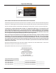
Section 4 • HMI Navigation HMI Navigation HMI screens are accessed by using the navigation buttons on each screen. When the HMI boots up, the compressor overview screen is displayed by default. The HMI Screens are divided into groups, all of which are accessible from the Menu Screen. Figure 4-1.
Section 4 • HMI Navigation The Menu Screen allows the user to view basic compressor configuration, status, active alarms and trips, as well as navigate to configuration, control, calibration, and diagnostics screens. An electronic copy of the compressor PLC manual is accessed from the Menu Screen.
Section 4 • HMI Navigation Main Menu (SP) Compressor Control Ͳ 1 of 3 (Suction Pressure) (PT) Compressor Control Ͳ 1 of 3 (Process Temperature) (DP) Compressor Control Ͳ 1 of 3 (Discharge Pressure) Compressor Control Ͳ 2 of 3 (SP) Visible when in Suction Pressure Mode only. (PT) Visible when in Process Temperature Mode only. Compressor Control Ͳ 3 of 3 (DP) Visible when in Discharge Pressure Mode only. Alarm and Trip Setpoints Ͳ 1 of 2 Alarm and Trip Setpoints Ͳ 2 of 2 Figure 4-2.
Section 4 • HMI Navigation Main Menu Instrument Cal. Ͳ Overview Pressure Calibration Ͳ 1 of 3 Temperature Calibration Ͳ 1 of 3 Slide Calibration Other Analog Device Calibration (SUPER to Edit) (SUPER to Edit) (SUPER to Edit) (SUPER to Edit) Pressure Calibration Ͳ 2 of 3 Temperature Calibration Ͳ 2 of 3 (SUPER to Edit) (SUPER to Edit) Pressure Calibration Ͳ 3 of 3 Temperature Calibration Ͳ 3 of 3 (SUPER to Edit) (SUPER to Edit) Volume Slide Details Figure 4-2.
Section 4 • HMI Navigation Main Menu After Cooler 1 (Step Type) (1) After Cooler 1 (VFD Type) (1) After Cooler 1 (Water Cooled) (1) After Cooler 2 (Step Type) (1) After Cooler 2 (VFD Type) (1) After Cooler 2 (Water Cooled) (1) (1) Visibility dependant on After Cooler Selections Figure 4-2.
Section 4 • HMI Navigation Main Menu Diagnostic Force Outputs Ͳ Authorized Users ONLY Goto Configure Mode (SUPER) (SUPER) Diagnostic Force Outputs Ͳ Authorized Users ONLY Shutdown (SUPER) (SUPER) Initial Baseline Running Data (1 of 2) Configuration Ͳ Authorized Users ONLY (SUPER) Initial Baseline Running Data (2 of 2) Set Date and Time Define Device Names Ͳ Instrumentation Define Device Names Ͳ Alarm and Trip – 1 (SUPER) (SUPER) Define Device Names Ͳ Devices and Vessels Define Device Names
Section 4 • HMI Navigation Main Menu Comms Diagnostics Condenser (Water Cooled) Event List (### Ͳ ###) Condenser (Step Type) Captured Data at Shutdown (1 of 2) Condenser (VFD Type) Captured Data at Shutdown (2 of 2) Oil Mixing Valve Oil Cooler (Step Type) Oil Cooler (VFD Type) Discharge Recycle Valve Liquid Injection Valve Liquid Injection Ͳ VPLUS Pump Figure 4-2. Screen Navigation Map - Condenser, Oil Mixing or Cooler, Liquid Injection, Misc.
Section 4 • HMI Navigation HMI Security SUPER Some items and screens on the HMI require a login to be viewed or changed. Login accounts are described below, each with its default password and level of access. • This user account is intended for site supervisors, managers, and superintendents.
Section 4 • HMI Navigation Figure 4-4.
4 – 10 / Blank Single Screw Compressor PLC Operation Manual • Vilter/Emerson • 35391CM
Section 5 • Configuration - Supervisor Level Configuration Screen - Supervisor Level NOTE Some screens may have inverted colors for ease of readability. by the user are included on this screen. To change option selections, press on the list selector and use the up, down, and enter buttons on the lower side of the screen. Most of the configuration that is specific to the compressor or package is completed at the factory and not accessible to the user. The options that may be configured Figure 5-1.
Section 5 • Configuration - Supervisor Level DATE AND TIME Allows the Real Time Clock in the PLC to be set. Pressing “Set Date and Time” will bring up the “Set Date and Time” pop-up screen. • Date and Time must be set in 24-hour format. • Pressing “Set Date and Time” will set the PLC time clock. • The HMI time clock will automatically synchronize to the PLC time clock. Figure 5-2.
Section 5 • Configuration - Supervisor Level PROCESS VARIABLE SOURCE OIL PUMP OPERATION Defines the pressure data used to control the capacity slide. Determines operation of the oil pump. • Local Hard-Wired Transducer – capacity slide and auto start/stop is controlled by the suction/discharge pressure transducer mounted on the compressor unit or package. • Common/Remote – capacity slide and auto start/ stop is controlled by suction/discharge header pressure data from a DCS/Central Controller.
Section 5 • Configuration - Supervisor Level PANELVIEW CONFIGURATION Pressing the “Panelview Configuration” button closes the compressor control application running on the HMI and opens the Factory Talk View ME Station configuration screens. INITIAL RUNNING DATA Pressing the “Initial Running Data” Button opens the Initial Running Data Screen which shows baseline data logged when the compressor was new. See Section X “Diagnostics Screens” for more information.
Section 5 • Configuration - Supervisor Level Editing Device Names DEVICES AND VESSELS The “Device Names” group of screens allows a user logged in as “SUPER” to edit names shown on the screen identifying compressor unit and package equipment, instrumentation, and alarm and trip designations. To edit the text fields in this group of screens, press on the string input button and use the popup keyboard to edit the text.
Section 5 • Configuration - Supervisor Level INSTRUMENTATION In Figure 5-5, this screen allows the user to edit device names shown on the screen for instrumentation installed on the compressor unit or package. Figure 5-5.
Section 5 • Configuration - Supervisor Level ALARM AND TRIP In Figure 5-6, this screen allows the user to edit the alarm and trip designation text that appears in the alarm and trip banners, alarm pop-up screen, and event list. In addition, messages for 5 user-defined alarms and trips may be defined on this screen. Figure 5-6.
Section 5 • Configuration - Supervisor Level Figure 5-6.
Section 6 • Instrument Calibration Calibration Main Screen NOTE Some screens may have inverted colors for ease of readability. Pressing the “Instrument Calibration” navigation button on the menu screen opens the instrument calibration group of screens. This group of screens allows the user to view and edit calibration data for specific instruments installed on the compressor unit or package.
Section 6 • Instrument Calibration Pressure Calibration Screen In Figure 6-2, the temperature calibration group of screens allows the user to change the pressure units displayed on the screen as well as calibrate pressure instruments. The following pressure units are available for display: • PSIG (Pounds/square inch gage) • PSIA (Pounds/square inch absolute) • kPa[A] (Kilopascals absolute) Pressure units are specific to individual pressure instruments.
Section 6 • Instrument Calibration CALIBRATE PRESSURE INSTRUMENT CALIBRATE TRANSDUCER TO A KNOWN PRESSURE To calibrate a pressure instrument, proceed with the following steps: There are two options when calibrating a transducer to a known pressure. 1. Select the units that the transducer is calibrated in. For example, for a transducer calibrated 0-200 PSIA, the transducer units selected shall be ‘PSIA.’ For a transducer calibrated -30inHg to 30PSIG, the transducer units selected shall be “inHg.” 2.
Section 6 • Instrument Calibration Temperature Calibration Screen The temperature calibration group of screens allows the user to change the temperature units displayed on the screen as well as calibrate temperature instruments. Four Temperature units are available for display: CALIBRATE TEMPERATURE INSTRUMENTS There two types of temperature instruments that can be calibrated, RTDs and temperature transmitters. To calibrate an RTD, proceed with the following steps.
Section 6 • Instrument Calibration Other Analog Device Calibration The Other Analog Device Calibration Screen allows the user to calibrate additional 4-20mA input devices. 4-20mA devices that can be calibrated: • Main Motor Amperage • Main Motor VFD Speed • Compressor and Motor Vibration Sensors CALIBRATE AN ADDITIONAL INSTRUMENT To calibrate an additional instrument, proceed with the following steps. 1. Enter the raw mA range (typically 4-20mA). 2. Enter the Span of the transmitter. 3.
Section 6 • Instrument Calibration Slide Calibration Screen The slide calibration screen allows the user to calibrate slide valve actuators. Both the capacity and volume slide actuators should be calibrated when one or more of these have occurred: • Compressor unit starting up for the first time. Slide Calibration Overview: • A new actuator motor has been installed. • Must be logged in as “SUPER” to calibrate slides.
Section 6 • Instrument Calibration CALIBRATE SLIDE VALVE ACTUATORS Slide valve actuators must be installed prior to calibration. Refer to Slide Valve Actuator Installation procedure in VSG/VSSG Compressor Unit manual (35391SSG). The following steps pertain to calibrating one slide valve actuator. Repeat procedure to calibrate other slide valve actuator. WARNING After stopping the compressor, allow the compressor and surrounding components to cool down prior to servicing.
Section 6 • Instrument Calibration 6. Select the Min or Max position of the slide valve to be calibrated. NOTE The “Slide calibration” screen displays twice the actuator output voltage. Both these values (% volume and % capacity) are meaningless until calibration has been completed. NOTE When the increase and decrease arrow buttons do not correspond to the increase and decrease shaft rotations, swap the blue and brown wires of the “power cable”.
Section 6 • Instrument Calibration 16. Quickly press and release the blue button on the actuator one more time. The red LED will stop flashing. The actuator is now calibrated and knows the minimum and maximum positions of the slide valve it controls. Now the capacity or volume channel of the PLC can be calibrated. 17. Use the down arrow button to move the actuator towards its minimum position while watching the mV readout on the screen.
6 – 10 / Blank Single Screw Compressor PLC Operation Manual • Vilter/Emerson • 35391CM
Section 7 • Compressor Control Setpoints Setpoints and Control Screens The setpoint and control screens relate to the operation and control of the compressor. Process and operational setpoints for the compressor and other equipment are adjustable within this group of screens. CHANGING SETPOINTS To change setpoints within the setpoint and control screens, the user must be logged in. Setpoints that may be adjusted by the logged in user appear as a white button that shows the current value of the setpoint.
Section 7 • Compressor Control Setpoints Compressor Control Setpoints NOTE Screens may have inverted colors for ease of readability. Compressor control setpoints can be controlled by suction pressure, process temperature or discharge pressure. Depending on which control scheme is chosen, compressor control screen 1 of 3 will display that chosen option.
Section 7 • Compressor Control Setpoints CAPACITY SLIDE VALVE • Load/Unload Interval time: This is the cycle time between making capacity slide position adjustments. • Max Load/Unload Adjustment per interval: This is the maximum amount the capacity position command may be adjusted by every time through the Load/ Unload Cycle timer. • Auto Stop Delay: Amount of time Auto Stop pressure must be met before the compressor will be commanded to stop.
Section 7 • Compressor Control Setpoints MAIN MOTOR VFD • Max Speed Increase/Decrease per interval: This is the maximum amount the main motor speed command may be adjusted by every time through the Load/ Unload Cycle timer. Forced Unload Rate: If a forced unload condition exists and the main motor is running above 50% speed, this is the rate it will decelerate until it reaches 50% speed and the capacity slide begins unloading. Figure 7-3.
Section 7 • Compressor Control Setpoints Compressor Control Setpoints Screen 1 - Discharge Pressure The Compressor Control Setpoints page 1 (Discharge Pressure) screen appears when navigating to “Compressor Control Setpoints” from the menu screen when Discharge Pressure control is selected. Setpoints for desired discharge pressure, capacity slide valve control, auto start-stop, and main motor VFD are settable within this screen.
Section 7 • Compressor Control Setpoints AUTO START/STOP • Auto Start Pressure: When discharge pressure is above this setpoint for the Auto Start Delay Time, the compressor will be commanded to start. • Auto Stop Pressure: When discharge pressure is below this setpoint and capacity slide position is below Minimum Slide Position for the Auto Stop Delay time, the compressor will be commanded to stop.
Section 7 • Compressor Control Setpoints Compressor Control Setpoints Screen 2 ANTI-RECYCLE before compressor is allowed to start. • Anti-Recycle Time: Defines the minimum amount of time after the compressor stops before it is allowed to start again. • Prelube Retry Wait Time: Amount of wait time before oil pump restarts if prelube oil pressure is not achieved. START UP • Prelube Time After Motor Start: Amount of time that minimum prelube pressure must be maintained after compressor main motor starts.
Section 7 • Compressor Control Setpoints will be energized after the compressor main motor stops, if installed. • Oil Drain Solenoid ON Time (at Stop): Amount of time the oil drain solenoid will be energized after the compressor main motor stops, if installed. VOLUME SLIDE ADJUSTMENT • Volume Slide Adjustment Factor: Offset that will be applied to the calculated volume slide target. OIL SEPARATOR HEATERS • Capacity Slide Range Adj.
Section 7 • Compressor Control Setpoints Compressor Control Setpoints Screen 3 VENTURI OIL RECOVERY • Cycle Time: Defines the ON and OFF time for the venturi oil recovery solenoids, if installed. HOTGAS BYPASS • ON/OFF Capacity Slide Position: Defines the capacity slide valve positions the hotgas bypass solenoid will turn ON below and OFF above, if installed. ECONOMIZER ENCLOSURE SETPOINTS • Enclosure Heater: Defines Enclosure Temperature setpoints to control the enclosure space heaters.
7 – 10 / Blank Single Screw Compressor PLC Operation Manual • Vilter/Emerson • 35391CM
Section 8 • Alarm and Trip Setpoints Alarm and Trip Setpoints NOTE Screens may have inverted colors for ease of readability. The compressor controller continuously monitors operational and process data and annunciates an alarm and/ or shuts the compressor down if any condition becomes abnormal. The alarm and trip points for some of the operational and process data are adjustable by the user in the alarm and trip setpoints screens.
Section 8 • Alarm and Trip Setpoints • Motor Winding Temperature: High Alarm and High Trip setpoints for temperature of the main motor windings, if motor winding RTDs are installed. • Motor Bearing Temperature: High Alarm and High Trip setpoints for temperature of the main motor bearings, if motor bearing RTDs are installed. • Process Temperature: Low Alarm, Low Trip, and High Alarm setpoints for process temperature, if it is being controlled or monitored.
Section 9 • Step and PID Device Control Screens Oil Mixing Valve Screen OIL MIXING VALVE SETPOINTS • Target Oil Injection Temp: Defines the desired temperature of oil entering the compressor. The mixing valve will adjust to maintain this temperature. • Deadband: Range above and below setpoint where the controller will not make adjustments to valve position. • PID Tuning: PID Calculations displayed to aid in tuning the PID loop. • Loop Update Time: Defines the PID controller loop time.
Section 9 • Step and PID Device Control Screens OIL COOLER (VFD TYPE) SETPOINTS • Start Oil Cooler Above: Defines the temperature the oil cooler fans will come on at minimum speed. • Target Oil Cooler Outlet Temperature: Defines the desired temperature of oil at the outlet of the oil cooler. The oil cooler fan speed will adjust to maintain this temperature. • Deadband: Range above and below setpoint where the controller will not make adjustments to fan speed.
Section 9 • Step and PID Device Control Screens OIL COOLER (STEP TYPE) SETPOINTS • Start Oil Cooler Above: Defines the temperature the first oil cooler step will come on. • Target Oil Cooler Outlet Temperature: Defines the desired temperature of oil at the outlet of the oil cooler. The controller will cycle fans on and off to maintain this temperature. • Plenum Heater OFF Temp: Defines the oil cooler outlet temperature at which the oil cooler plenum heater turns OFF (if used).
Section 9 • Step and PID Device Control Screens Aftercooler Screens AFTERCOOLER (VFD TYPE) SETPOINTS • Start Aftercooler Above: Defines the temperature the aftercooler fans will come on at minimum speed. • Target Aftercooler Outlet Temperature: Defines the desired temperature of gas at the outlet of the aftercooler. The aftercooler fan speed will adjust to maintain this temperature. • Deadband: Range above and below setpoint where the controller will not make adjustments to fan speed.
Section 9 • Step and PID Device Control Screens AFTERCOOLER (STEP TYPE) SETPOINTS • Start Aftercooler Above: Defines the temperature the first aftercooler step will come on. • Target Aftercooler Outlet Temperature: Defines the desired temperature of gas at the outlet of the aftercooler. The controller will cycle fans on and off to maintain this temperature. • Deadband: Range above and below setpoint where the controller will not add or remove any steps.
Section 9 • Step and PID Device Control Screens WATER COOLED AFTERCOOLER SETPOINTS • Open Valve Above: Defines the temperature the aftercooler water supply valve will open to minimum position. • Target Aftercooler Outlet Temperature: Defines the desired temperature of gas at the outlet of the aftercooler. The aftercooler water supply valve position will adjust to maintain this temperature.
Section 9 • Step and PID Device Control Screens Condenser Screens CONDENSER (STEP TYPE) SETPOINTS • Start Condenser Above: Defines the pressure the first condenser step will come on. • Target Condensing Pressure: Defines the desired pressure of gas at the condenser. The controller will cycle fans on and off to maintain this temperature. • Deadband: Range above and below setpoint where the controller will not add or remove any steps.
Section 9 • Step and PID Device Control Screens CONDENSER (VFD TYPE) SETPOINTS • Start Condenser Above: Defines the temperature the condenser fans will come on at minimum speed. • Target Condensing Pressure: Defines the desired pressure of gas at the condenser. The condenser fan speed will adjust to maintain this pressure. • Deadband: Range above and below setpoint where the controller will not make adjustments to fan speed. • PID Tuning: PID Calculations displayed to aid in tuning the PID loop.
Section 9 • Step and PID Device Control Screens WATER COOLED CONDENSER SETPOINTS • Open Valve Above: Defines the pressure at which the aftercooler water supply valve will open to minimum position. • Target Condensing Pressure: Defines the desired pressure of gas at the condenser. The condenser water supply valve position will adjust to maintain this pressure. • Deadband: Range above and below setpoint where the controller will not make adjustments to water supply valve positon.
Section 9 • Step and PID Device Control Screens Liquid Injection Valve Screens LIQUID INJECTION VALVE SETPOINTS • Open Valve Above: Defines the temperature at which the liquid injection valve will open to minimum position. • Target Discharge Temperature: Defines the desired temperature of gas and oil discharging from the compressor. The liquid injection valve position will adjust to maintain this temperature.
Section 9 • Step and PID Device Control Screens LIQUID INJECTION (VPLUS PUMP) SETPOINTS • Start Pump At: Defines the temperature at which the VPLUS pump will start at its minimum speed. • Target Discharge Temperature: Defines the desired temperature of gas and oil discharging from the compressor. The VPLUS pump will adjust speed to maintain this temperature. • Deadband: Range above and below setpoint where the controller will not make adjustments to the VPLUS pump speed.
Section 9 • Step and PID Device Control Screens Discharge Recycle Valve Screen DISCHARGE RECYCLE VALVE SETPOINTS • Target Recycle Control Pressure: Defines the pressure at which the discharge recycle valve will begin to open. • Deadband: Range above and below setpoint where the controller will not make adjustments to the recycle valve position. • PID Tuning: PID Calculations displayed to aid in tuning the PID loop. • Loop Update Time: Defines the PID controller loop time.
Section 9 • Step and PID Device Control Screens Volume Slide Details Screen VOLUME SLIDE DETAILS • Shows details of the volume slide calculation. • Allows the user to put the volume slide in manual mode. (Must be logged in as “SUPER”). 10 Minute Timer • Volume slide will switch back to Auto Mode after 10 minutes of idle in Manual Mode Figure 9-13.
Section 9 • Step and PID Device Control Screens Start Menu Popup Screen Pressing “Start Menu” on the compressor or system overview screen will open the “Start Menu” popup screen. The “Start Menu” screen allows the user to change operating modes and start the compressor. • Auto: Pressing the Auto pushbutton puts the compressor loading control in Auto mode. • Remote: Pressing the remote pushbutton puts the compressor loading control in remote mode.
Section 10 • Diagnostic Screens IO/Comms Diagnostics Screen COMMS DIAGNOSTICS AND I/O STATUS NOTE Some screens may have inverted colors for ease of readability. The IO/Comms Diagnostics Screen is divided into 3 sections. • SYSTEM INFORMATION • Shows basic information about the Compressor PLC panel: Vilter sales order number, Software revision, IP addresses, hardware information, and firmware revisions of compressor PLC and HMI.
Section 10 • Diagnostic Screens Event List Screen The event list is a running log of alarm, trip, and status information. The event list shows the last 400 events logged by the compressor PLC, most recent is at the top of the screen. Each event is logged with a time and date stamp. To scroll through past events, use the navigation buttons at the bottom of the screen. Figure 10-2.
Section 10 • Diagnostic Screens Diagnostics Forced Outputs Screen The force outputs screen allows a user logged in as “SUPER” to force discrete and analog outputs to verify operation of devices on the compressor unit or package. Outputs that are available to force depend on the configuration for a specific compressor machine or package. • Pressing a force button forces ON the PLC output for that particular device.
Section 10 • Diagnostic Screens Captured Data at Shutdown Screen The captured data at shutdown screen shows process and operational data at the time the compressor shuts down. Data from the last 5 shutdowns are logged. Each shutdown is given a time and date stamp. The most recent shutdown is on the left. Figure 10-4.
Section 10 • Diagnostic Screens Initial Baseline Running Data Screen The Initial Baseline Running Data screen shows data collected when the compressor is first started up. Vilter Service Technicians or Engineers only may log this data. This is to give a reference point for comparing operational and process data to a baseline set of data collected when the compressor or package was new. Figure 10-5.
10 – 6 / Blank Single Screw Compressor PLC Operation Manual • Vilter/Emerson • 35391CM
Section 11 • Alarms, Trips, Status Information & Troubleshooting Alarm Listing ALARMS AND TRIPS Process and Operational data of the compressor unit is continuously monitored by the compressor PLC. If an abnormal condition is detected, an alarm or trip will be annunciated. • Alarms • Warns of an abnormal condition. Compressor may continue to run. A scrolling display at the top of the overview and menu screens shows all active alarms and trips, see Figure 11-1.
Section 11 • Alarms, Trips, Status Information & Troubleshooting Alarm Listing The following table shows all possible alarms and trips and possible causes. Some alarms and trips are application specific, and do not apply unless a specific option is selected. To reset alarms or trips press the “Alarm Reset” Button on the overview screen. If the condition is cleared, the alarm will reset. If the condition is not cleared, the alarm will remain active. Table 11-1.
Section 11 • Alarms, Trips, Status Information & Troubleshooting Alarm Message Cause(s) Notes (A017) Alarm: Low Process Temperature Process Temperature falls below Process Temperature Low Alarm Setpoint in Process Temperature control or if displaying Process Temperature. Active if controlling or displaying Process Temperature (A018) Alarm: High Process Temperature Process Temperature exceeds Process Temperature High Alarm Setpoint in Process Temperature control or if displaying Process Temperature.
Section 11 • Alarms, Trips, Status Information & Troubleshooting Alarm Message (A029) Alarm: Low Oil Pressure - Start Cause(s) Notes Net Oil Pressure (Oil Manifold Pressure - Suction Pressure) falls below Net Oil Pressure Low Alarm Setpoint after before Warmup is complete (A030) Alarm: (Unassigned) (A031) Alarm: Out of Range: Oil Cooler Inlet Temp Oil Cooler Inlet Temperature Instrument is Disconnected or Raw value is less than 3.5 mA or Greater than 20.5 mA (if using a 4-20mA Temperature Transmitter).
Section 11 • Alarms, Trips, Status Information & Troubleshooting Alarm Message Cause(s) Notes (A040) Alarm: Out of Range: Discharge Recycle Control Pressure Discharge Recycle Control Pressure Instrument is Disconnected or Raw value is less than 3.5 mA or Greater than 20.5 mA. Active if Controlling Discharge Recycle Valve (A041) Alarm: Out of Range: Oil Separator Outlet Pressure Oil Separator Outlet Pressure Instrument is Disconnected or Raw value is less than 3.5 mA or Greater than 20.5 mA.
Section 11 • Alarms, Trips, Status Information & Troubleshooting Alarm Message Cause(s) Notes (A058) Alarm: Inlet Scrubber High High Level Inlet Scrubber High High Liquid Level Active if Vane Type Inlet Scrubber is Switch Activated (Selected Action = Present ALARM) (A059) Alarm: Inlet Scrubber Low Low Level Inlet Scribber Low Low Level Switch Activated (Selected Action = ALARM) Active if Vane Type Inlet Scrubber is Present (A060) Alarm: Upper Inlet Scrubber High Level Inlet Scrubber Upper Section H
Section 11 • Alarms, Trips, Status Information & Troubleshooting Alarm Message Cause(s) Notes (A080) Alarm: User Defined Alarm 2 Message Defined in "Device Names" Screens (A081) Alarm: User Defined Alarm 3 Message Defined in "Device Names" Screens (A082) Alarm: User defined Alarm 4 Message Defined in "Device Names" Screens (A083) Alarm: User defined Alarm 5 Message Defined in "Device Names" Screens (A089) Alarm: Oil Cooler Fan VFD Fault Fault Contact open on Oil Cooler VFD If controlling a
Section 11 • Alarms, Trips, Status Information & Troubleshooting Alarm Message (A106) Alarm: High Methane Gas %LEL Cause(s) Methane Concentration in Building Exceeds Methane Gas %LEL High Alarm Setpoint.
Section 11 • Alarms, Trips, Status Information & Troubleshooting Trip Listing Table 11-2. Trip Listing Trip Message Cause(s) Notes (T001) Trip: MCR Not Energized/EStop Active Emergency Stop Button on PLC panel Pressed, Loss of Power (T002) Trip: PLC to Central Comms Faulted Loss of Communication with DCS/ Watchdog Active if Control by Central - Settable Communications Communications is selected Watchdog Timer Expired.
Section 11 • Alarms, Trips, Status Information & Troubleshooting Trip Message Cause(s) Notes (T015) Trip: Low Oil Injection Temperature Oil Injection Temperature is Below "Oil Injection Temperature" Low Trip Setpoint after compressor has completed pre-lube and warm up stages.
Section 11 • Alarms, Trips, Status Information & Troubleshooting Trip Message Cause(s) (T028) Trip: High Oil Filter Differential - Run Oil Filter Differential (Filter In Pressure - Oil Manifold Pressure) exceeds Oil Filter Differential - Run High Trip Setpoint when compressor is running and after Oil Filter Differential Start-Run Changeover Timer expires.
Section 11 • Alarms, Trips, Status Information & Troubleshooting Trip Message Cause(s) Notes (T039) Trip: Out of Range: Main Motor Amps Main Motor Current Transmitter is Disconnected or Raw value is less than 3.5 mA or Greater than 20.5 mA. (T040) Trip: Out of Range: Capacity Slide Position Capacity Slide Cable is Disconnected or Raw value is less than 0 mV or Greater than 5200 mV.
Section 11 • Alarms, Trips, Status Information & Troubleshooting Trip Message Cause(s) Notes (T054) Trip: High Motor Vibration Sensor 2 Motor Vibration exceeds Motor Vibration High Trip Setpoint (Sensor 2) Active if Displaying Motor Vibration Sensor 2 (T055) Trip: High Compressor Vibration - Sensor 1 Compressor Vibration exceeds Compressor Vibration High Trip Setpoint (Sensor 1) Active if Displaying Compressor Vibration Sensor 1 (T056) Trip: High Compressor Vibration - Sensor 2 Compressor Vibratio
Section 11 • Alarms, Trips, Status Information & Troubleshooting Trip Message Cause(s) Notes (T078) Trip: (Unassigned) (T079) Trip: User defined Trip 1 Message Defined in "Device Names" Screens (T080) Trip: User Defined Trip 2 Message Defined in "Device Names" Screens (T081) Trip: User Defined Trip 3 Message Defined in "Device Names" Screens (T082) Trip: User defined Trip 4 Message Defined in "Device Names" Screens (T083) Trip: User defined Trip 5 Message Defined in "Device Names" Screens
Section 11 • Alarms, Trips, Status Information & Troubleshooting Trip Message Cause(s) (T108) Trip: Smoke Detector Tripped Smoke Detector Trip Contact opened, detected smoke in compressor enclosure Notes If compressor is in an enclosure (T109) Trip: (Unassigned) (T110) Trip: High Enclosure Temperature Temperature inside Enclosure exceeds Enclosure Temperature - High Trip Setpoint If compressor is in an enclosure (T111) Trip: Out of Range: 4-20 mA Caphold Target 4-20mA Caphold Input is Disconnected o
Section 11 • Alarms, Trips, Status Information & Troubleshooting Status Messages and Compressor State Indicator Status messages are used to indicate compressor status information to the user. Status messages are used to inform the user of any of the following conditions.
Section 11 • Alarms, Trips, Status Information & Troubleshooting Status Message (S011) Status: Auto Cycle Stop - Discharge Pressure Notes Auto Start-Stop function is enabled and "Stop" Pressure has been reached.
Section 11 • Alarms, Trips, Status Information & Troubleshooting Status Message Notes (S048) Status: Aftercooler 1 Fan 4 FORCED ON (S049) Status: Aftercooler 1 Fan 5 FORCED ON (S050) Status: Aftercooler 1 Fan 6 FORCED ON (S051) Status: Aftercooler 1 Fan 7 FORCED ON (S052) Status: Aftercooler 1 Fan 8 FORCED ON (S053) Status: Aftercooler 1 Fan 9 FORCED ON (S054) Status: Aftercooler 1 Fan 10 FORCED ON (S055) Status: Aftercooler 2 VFD FORCED ON (S056) Status: Aftercooler 2 Fan 1 FORCED ON (S057) Status: After
Section 11 • Alarms, Trips, Status Information & Troubleshooting Status Message Notes (S089) Status: Hotgas SOV FORCED ON (S090) Status: Venturi Oil Recovery SOVs FORCED ON (S091) Status: Inlet Scrubber Drain Pump/SOV FORCED ON (S092) Status: Inlet Scrubber Backup SOV FORCED ON (S093) Status: Outlet Scrubber Drain Pump/SOV FORCED ON (S094) Status: Outlet Scrubber Backup SOV FORCED ON (S095) Status: Enclosure Vent Fans FORCED ON (S096) Status: Enclosure Heaters FORCED ON (S097) Status: Evap Condenser Pump
Section 11 • Alarms, Trips, Status Information & Troubleshooting Troubleshooting IF THE COMPRESSOR WILL NOT START In order to initiate a start at the compressor, make sure all permissives to initiate a start are met.
Section 12 • Communications with a Central Controller/DCS Communication with a Central Controller/DCS Central Controller/DCS. It is only necessary to write watchdog logic when the Central Controller/DCS is sending commands to the compressor PLC. If reading data only, the Watchdog timer is not used. IIt is possible for a central controller/DCS to read live data and other information from the compressor PLC as well as send commands to the compressor PLC.
Section 12 • Communications with a Central Controller/DCS Table 12-1. Engineered Units Value Interpretation (INT_OUT[x]) Pressure Units INT_OUT[x] Value Temperature Units INT_OUT[x] Value PSIG 0 Degrees Fahrenheit 0 PSIA (PSID) 1 Degrees Celsius 1 kPa[A] (kPa[D]) 2 Kelvin 2 kPa[G] 12 Degrees Rankine 3 kg/cm^2[A] (kg/cm^2[D]) 3 kg/cm^2[G] 13 inHg (vac) PSIG (pressure) 4 inWC 15 Bar[A] (Bar[D]) 6 Bar[G] 16 Torr[A] (Torr[D]) 7 Torr[G] 17 Table 12-2.
Section 12 • Communications with a Central Controller/DCS Interface Tag Description Units REAL_OUT[20] Phase A Winding Temp INT_OUT[20] REAL_OUT[21] Phase B Winding Temp INT_OUT[21] REAL_OUT[22] Phase C Winding Temp INT_OUT[22] REAL_OUT[23] ODE Bearing Temp INT_OUT[23] REAL_OUT[24] DE Bearing Temp INT_OUT[24] REAL_OUT[25] Motor Vibration 1 in/sec REAL_OUT[26] Motor Vibration 2 in/sec REAL_OUT[27] Compressor Vibration 1 in/sec REAL_OUT[28] Compressor Vibration 2 in/sec REAL_OUT[
Section 12 • Communications with a Central Controller/DCS Interface Tag REAL_OUT[61] Description Methane Detector LEL Units % LEL REAL_OUT[62] INT_OUT[62] REAL_OUT[63] INT_OUT[63] REAL_OUT[64] INT_OUT[64] REAL_OUT[65] EPCS Low Side Pressure INT_OUT[65] REAL_OUT[66] EPCS High Side Pressure INT_OUT[66] REAL_OUT[67] INT_OUT[67] REAL_OUT[68] INT_OUT[68] REAL_OUT[69] INT_OUT[69] REAL_OUT[70] Runtime Hours Hours REAL_OUT[71] Runtime Mins Minutes REAL_OUT[72] Resettable Runtime Hours H
Section 12 • Communications with a Central Controller/DCS Interface Tag Description Units REAL_OUT[102] Oil Separator Temp DEGF REAL_OUT[103] Oil Injection Temp DEGF REAL_OUT[104] Oil Separator Outlet Temp DEGF REAL_OUT[106] Suction Pressure PSIA REAL_OUT[107] Discharge Pressure PSIA REAL_OUT[108] Filter In Pressure PSIA REAL_OUT[109] Filter Out Pressure PSIA REAL_OUT[110] Oil Separator Out Pressure PSIA REAL_OUT[111] Oil Separator Pressure Drop PSID REAL_OUT[112] Filter Diffe
Section 12 • Communications with a Central Controller/DCS Interface Tag Description Units REAL_OUT[143] Aftercooler 1 VFD Speed % Speed (100%=60Hz) REAL_OUT[144] Aftercooler 2 VFD Speed % Speed (100%=60Hz) REAL_OUT[146] Discharge Recycle Control Pressure PSIA REAL_OUT[147] Discharge Recycle Commanded Postion % Position REAL_OUT[150] Condensing Pressure PSIA REAL_OUT[151] Condenser VFD Speed % Speed (100%=60Hz) REAL_OUT[153] Inlet Scrubber Inlet Pressure PSIA REAL_OUT[154] Inlet Scru
Section 12 • Communications with a Central Controller/DCS Interface Tag Description Units REAL_OUT[183] REAL_OUT[184] REAL_OUT[185] REAL_OUT[186] REAL_OUT[187] REAL_OUT[188] REAL_OUT[189] REAL_OUT[190] REAL_OUT[191] REAL_OUT[192] REAL_OUT[193] REAL_OUT[194] REAL_OUT[195] REAL_OUT[196] REAL_OUT[197] REAL_OUT[198] REAL_OUT[199] Single Screw Compressor PLC Operation Manual • Vilter/Emerson • 35391CM 12 – 7
Section 12 • Communications with a Central Controller/DCS Alarm and Trip Data Alarm and Trip Data is presented in Double Integer Format. To interpret the Alarm and Trip data, it is necessary to address the specific bits of the Double Integer. Table 12-3. Alarm Data Interface Tag ALARMS AND TRIPS (Data Type = DINT) Description BOOL_OUT[1].0 (A001) Alarm: (Unassigned) BOOL_OUT[1].1 (A002) Alarm: PLC to Central Comms Faulted BOOL_OUT[1].2 (A003) Alarm: High Main Motor Amps BOOL_OUT[1].
Section 12 • Communications with a Central Controller/DCS Interface Tag Description BOOL_OUT[2].1 (A034) Alarm: Out of Range: Aftercooler 1 Outlet Temp BOOL_OUT[2].2 (A035) Alarm: Out of Range: Aftercooler 2 Outlet Temp BOOL_OUT[2].3 (A036) Alarm: Out of Range: Inlet Scrubber Inlet Pressure BOOL_OUT[2].4 (A037) Alarm: Out of Range: Inlet Scrubber Outlet Pressure BOOL_OUT[2].5 (A038) Alarm: Out of Range: Outlet Scrubber Inlet Pressure BOOL_OUT[2].
Section 12 • Communications with a Central Controller/DCS Interface Tag Description BOOL_OUT[3].10 (A075) Alarm: Outlet Scrubber High Pressure Drop BOOL_OUT[3].11 (A076) Alarm: Outlet Scrubber Condensate Pump Starter Fault BOOL_OUT[3].12 (A077) Alarm: (Unassigned) BOOL_OUT[3].13 (A078) Alarm: (Unassigned) BOOL_OUT[3].14 (A079) Alarm: BOOL_OUT[3].15 (A080) Alarm: BOOL_OUT[3].16 (A081) Alarm: BOOL_OUT[3].17 (A082) Alarm: BOOL_OUT[3].18 (A083) Alarm: BOOL_OUT[3].
Section 12 • Communications with a Central Controller/DCS Interface Tag Description BOOL_OUT[4].19 (A116) Alarm: (Unassigned) BOOL_OUT[4].20 (A117) Alarm: (Unassigned) BOOL_OUT[4].21 (A118) Alarm: (Unassigned) BOOL_OUT[4].22 (A119) Alarm: (Unassigned) BOOL_OUT[4].23 (A120) Alarm: (Unassigned) BOOL_OUT[4].24 (A121) Alarm: (Unassigned) BOOL_OUT[4].25 (A122) Alarm: (Unassigned) BOOL_OUT[4].26 (A123) Alarm: (Unassigned) BOOL_OUT[4].27 (A124) Alarm: (Unassigned) BOOL_OUT[4].
Section 12 • Communications with a Central Controller/DCS Table 12-4. Trip Data Interface Tag TRIPS (Data Type = Double Integer) Description BOOL_OUT[11].0 (T001) Trip: MCR Not Energized/E-Stop Active BOOL_OUT[11].1 (T002) Trip: PLC to Central Comms Faulted BOOL_OUT[11].2 (T003) Trip: High Main Motor Amps BOOL_OUT[11].3 (T004) Setpoint out of Range - See Menu Screen BOOL_OUT[11].4 (T005) Trip: False Start Detected BOOL_OUT[11].5 (T006) Trip: Low Separator Oil Level BOOL_OUT[11].
Section 12 • Communications with a Central Controller/DCS Interface Tag Description BOOL_OUT[12].6 (T039) Trip: Out of Range: Main Motor Amps BOOL_OUT[12].7 (T040) Trip: Out of Range: Capacity Slide Position BOOL_OUT[12].8 (T041) Trip: Out of Range: Volume Slide Position BOOL_OUT[12].9 (T042) Trip: Out of Range: Process Temp BOOL_OUT[12].10 (T043) Trip: Out of Range: Motor RTD Phase A BOOL_OUT[12].11 (T044) Trip: Out of Range: Motor RTD Phase B BOOL_OUT[12].
Section 12 • Communications with a Central Controller/DCS Interface Tag Description BOOL_OUT[13].15 (T080) Trip: User Defined Trip 2 BOOL_OUT[13].16 (T081) Trip: User Defined Trip 3 BOOL_OUT[13].17 (T082) Trip: User Defined Trip 4 BOOL_OUT[13].18 (T083) Trip: User Defined Trip 5 BOOL_OUT[13].19 (T084) Trip: (Unassigned) BOOL_OUT[13].20 (T085) Trip: (Unassigned) BOOL_OUT[13].21 (T086) Trip: (Unassigned) BOOL_OUT[13].22 (T087) Trip: (Unassigned) BOOL_OUT[13].
Section 12 • Communications with a Central Controller/DCS Interface Tag Description BOOL_OUT[14].24 (T121) Trip: (Unassigned) BOOL_OUT[14].25 (T122) Trip: (Unassigned) BOOL_OUT[14].26 (T123) Trip: (Unassigned) BOOL_OUT[14].27 (T124) Trip: (Unassigned) BOOL_OUT[14].28 (T125) Trip: (Unassigned) BOOL_OUT[14].29 (T126) Trip: (Unassigned) BOOL_OUT[14].30 (T127) Trip: (Unassigned) BOOL_OUT[14].
Section 12 • Communications with a Central Controller/DCS Status Data Compressor Status Data is presented in Double Integer Format. To interpret the compressor status data, it is necessary to address the specific bits of the Double Integer. Table 12-5. Status Data Interface Tag STATUS (Data Type = DINT, Length = 10) Description BOOL_OUT[21].0 (S001) Status: Compressor Stopped BOOL_OUT[21].1 (S002) Status: Compressor Started BOOL_OUT[21].2 (S003) Status: NOT USED BOOL_OUT[21].
Section 12 • Communications with a Central Controller/DCS Interface Tag Description BOOL_OUT[22].1 (S034) Status: Oil Cooler Fan 1 FORCED ON BOOL_OUT[22].2 (S035) Status: Oil Cooler Fan 2 FORCED ON BOOL_OUT[22].3 (S036) Status: Oil Cooler Fan 3 FORCED ON BOOL_OUT[22].4 (S037) Status: Oil Cooler Fan 4 FORCED ON BOOL_OUT[22].5 (S038) Status: Oil Cooler Fan 5 FORCED ON BOOL_OUT[22].6 (S039) Status: Oil Cooler Fan 6 FORCED ON BOOL_OUT[22].7 (S040) Status: Oil Cooler Fan 7 FORCED ON BOOL_OUT[22].
Section 12 • Communications with a Central Controller/DCS Interface Tag Description BOOL_OUT[23].10 (S075) Status: Condenser Fan 9 FORCED ON BOOL_OUT[23].11 (S076) Status: Condenser Fan 10 FORCED ON BOOL_OUT[23].12 (S077) Status: Condenser Water Valve FORCED ON BOOL_OUT[23].13 (S078) Status: VPLUS Pump FORCED ON BOOL_OUT[23].14 (S079) Status: Liquid Injection Valve Air SOV FORCED ON BOOL_OUT[23].15 (S080) Status: Discharge Recycle Air SOV FORCED ON BOOL_OUT[23].
Section 12 • Communications with a Central Controller/DCS Interface Tag Description BOOL_OUT[24].19 (S116) Status: Volume Slide Exercise Active BOOL_OUT[24].20 (S117) Status: Volume Slide In Manual Mode BOOL_OUT[24].21 NOT USED BOOL_OUT[24].22 (S119) Status: Compressor Ready BOOL_OUT[24].23 (S120) Status: NOT USED BOOL_OUT[24].24 (S121) Status: NOT USED BOOL_OUT[24].
Section 12 • Communications with a Central Controller/DCS States of Discrete I/O States of the Discrete Inputs and Outputs is presented in Double Integer Format. To interpret the IO State data, it is necessary to address the specific bits of the Double Integer. Table 12-6. Discrete Input Interface Tag Discrete Input States (Data Type = DINT) Description BOOL_OUT[31].0 Aftercooler 1 Fan Aux Contact (Step Type) BOOL_OUT[31].1 Aftercooler 1 Fan Aux Contact (Step Type) BOOL_OUT[31].
Section 12 • Communications with a Central Controller/DCS Interface Tag Description BOOL_OUT[32].1 Condenser Fan Aux Contact (Step Type) BOOL_OUT[32].2 Condenser Fan Aux Contact (Step Type) BOOL_OUT[32].3 Condenser Fan Aux Contact (Step Type) BOOL_OUT[32].4 Evap Condenser Pump Running BOOL_OUT[32].5 Condenser VFD Faulted (VFD Type) BOOL_OUT[32].6 Condenser VFD Running BOOL_OUT[32].7 E-stop OK and MCR energized BOOL_OUT[32].8 NOT USED BOOL_OUT[32].9 NOT USED BOOL_OUT[32].
Section 12 • Communications with a Central Controller/DCS Interface Tag Description BOOL_OUT[33].10 Upper Outlet Scrubber High Alarm (Coalescing) BOOL_OUT[33].11 Upper Outlet Scrubber High Trip (Coalescing) BOOL_OUT[33].12 Outlet Scrubber Condensate Drain Cutin Switch BOOL_OUT[33].13 Outlet Scrubber Condensate Drain Cutout Switch BOOL_OUT[33].14 Outlet Scrubber High Alarm (Vane type) BOOL_OUT[33].15 Outlet Scrubber High Trip (Vane Type) BOOL_OUT[33].
Section 12 • Communications with a Central Controller/DCS Interface Tag Description BOOL_OUT[36].14 Aftercooler 2 Fan Starter (Step Type) BOOL_OUT[36].15 Aftercooler 2 Fan Starter (Step Type) BOOL_OUT[36].16 Aftercooler 2 Fan Starter (Step Type) BOOL_OUT[36].17 Aftercooler 2 Fan Starter (Step Type) BOOL_OUT[36].18 Aftercooler 2 Fan Starter (Step Type) BOOL_OUT[36].19 Aftercooler 2 Fan Starter (Step Type) BOOL_OUT[36].20 Aftercooler 2 Fan Starter (Step Type) BOOL_OUT[36].
Section 12 • Communications with a Central Controller/DCS Interface Tag Description BOOL_OUT[37].23 Main Motor Start Command BOOL_OUT[37].24 Oil Cooler Fan Starter (Step Type) BOOL_OUT[37].25 Oil Cooler Fan Starter (Step Type) BOOL_OUT[37].26 Oil Cooler Fan Starter (Step Type) BOOL_OUT[37].27 Oil Cooler Fan Starter (Step Type) BOOL_OUT[37].28 Oil Cooler Fan Starter (Step Type) BOOL_OUT[37].29 Oil Cooler Fan Starter (Step Type) BOOL_OUT[37].
Section 12 • Communications with a Central Controller/DCS Compressor State and Mode Indicator The state of the compressor state indicator shown on the compressor and system overview screens can be monitored. Table 12-8.
Section 12 • Communications with a Central Controller/DCS Table 12-10.
35391CM Rev. 0 (8/13) Emerson and Vilter are trademarks of Emerson Electric Co. or one of its affiliated companies. © 2013 Emerson Climate Technologies, Inc. All rights reserved. Printed in the USA.