
Specifications

2 – 13
Section 2 • Operational Descriptions
Single Screw Compressor PLC Operation Manual • Vilter/Emerson • 35391CM
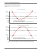
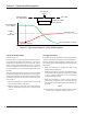
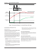
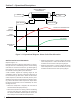
Figure 2-8. Operational Diagram - Air Cooled Oil Cooler (VFD Type)
TARGET
OUTPUT
TEMPERATURE
START
TEMPERATURE
MINIMUM FAN
SPEED
TE
OIL COOLER
TEMPERATURE (OIL COOLER
OUTLET TEMPERATURE)
FAN SPEED
AIR COOLED OIL COOLER (VFD TYPE)
Reference Figure 2-8
If installed, the VFD type air cooled oil cooler is a heat
exchanger that uses one or more fans running on a VFD
to control the oil temperature at its outlet.
A PID controller adjusts the speed of the fan(s) to control
the temperature at the outlet of the oil cooler. When the
temperature of the oil at the outlet of the cooler exceeds
the desired temperature plus a deadband, the fan(s) will
increase speed to add more cooling. When outlet tem-
perature drops below the desired temperature minus a
deadband, the fan(s) will decrease speed.
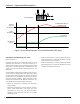
• When the compressor is stopped, the oil cooler fan(s)
will stop.
• When the compressor is running and the oil cool-
er outlet temperature rises above the “Oil Cooler
Start” temperature set in the “VFD Type Oil Cooler
Setpoints” screen, the fan(s) will start at a settable
minimum speed.
• When the compressor is running and the oil cooler
outlet temperature is above the deadband, the PID
controller will increase fan speed.
• When the compressor is running and the oil cooler
outlet temperature is below the deadband, the PID
controller will decrease fan speed.
OIL COOLER TEMPERATURES
It is possible to monitor Oil Cooler Inlet Temperature,
and monitor Oil Cooler Outlet Temperature if an oil cool-
er is not being controlled.
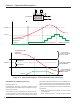
OIL COOLER STANDBY HEATER
If installed, a heater within the remote oil cooler is con-
trolled by the compressor PLC to maintain warm oil. The
heater cycles on and off to maintain a desired oil cooler
outlet temperature range. Setpoints to control the Oil
Cooler Standby Heater are on the “Oil Cooler Control
Setpoints (Step or VFD Type)” Screen.