VSG/VSSG compact logix PLC Operation manual FOR UNITS BUILT BEFORE JULY 1, 2013
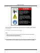
Important Note Before applying power to the control panel, all wiring to the panel shall be installed per NEC. Specifically check for proper voltage and that the neutral is grounded at the source. An equipment ground should also be run to the panel. *See Wiring Instructions and Diagrams before proceeding. NOTES: • • • Before start-up you need to enter all system values and options, see section on Setpoint Values.
/Blank VSG/VSSG • Compact Logix PLC Manual •Vilter/Emerson • 35391CL
Table of Contents Important Note ................................................................................................. 3 VSG/VSSG STANDARD VILTER WARRANTY STATEMENT ...................................... 6 Operational Flow Charts .................................................................................... 7 Main Screen..................................................................................................... 15 Log On Screen .....................................................
VSG/VSSG STANDARD VILTER WARRANTY STATEMENT Seller warrants all new single screw gas compression units and bareshaft single screw compressors manufactured by it and supplied to Buyer to be free from defects in materials and workmanship for a period of (a) eighteen (18) months from the date of shipment or (b) twelve (12) months from the date of installation at the end user’s location, whichever occurs first.
Operational Flow Charts Requirements to Start Compressor Oil Separator Temp > Oil Sep Start Trip Setpt. Volume and Capacity slides are less than 5 %.
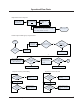
Operational Flow Charts Suction Pressure Control Capacity Inc WAIT No No No Is Suction Press > Suct Press Cap Inc Setpt? Yes Is Cap Inc ON Timer Timed Out? Yes Is Cap Inc OFF Timer Timed Out? Yes Reset Cap Inc Timers Yes Is Cap Dec. OFF Timer Timed Out? Yes Reset Cap Dec Timers No No No Capacity Dec Is Suction Press < Suct Press Cap Dec Setpt? Yes Is Cap Dec.
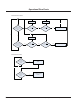
Operational Flow Charts Oil Cooler Fan Control (Selectable Control Optional) PID Control 30 sec delay Oil Cooler outlet temp > set pt? Unit Start No Yes Increase Speed Yes Decrease Speed No Oil Cooler outlet temp < set pt? PID Control Oil Temperature Control Valve 30 sec delay Oil injection temp > set pt? Unit Start No Yes Modulate valve Yes Modulate valve No Oil injection temp < set pt? VSG/VSSG • Compact Logix PLC Manual •Vilter/Emerson • 35391CL 9
Operational Flow Charts Delayed Lockout Timers WARNING: FOR THE FOLLOWING SHUTDOWNS, A DELAYED RESTART MAY OCCUR: High Discharge Pressure Failure High Compressor Discharge Temp Failure High Package Outlet Temp Failure High Oil Injection Temp Failure Is Shutdown Value Below Reset Value? Shutdown due to Operational Failure Has It been *H1 Hours Since Shutdown? Yes H1= Timer Set Between .5-6 Hours. Default Value= .
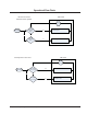
Operational Flow Charts Capacity Control Using Suction Pressure Control Setpoints Start Has Decrease at Start (Expired 15 sec.
Operational Flow Charts Capacity Control Using Discharge Pressure Control Setpoints Start Has Decrease at Start (Expired 15 sec.
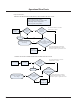
Operational Flow Charts Compressor Operation with VFD Drive Check/Adjust Capacity Slide No Start Compressor Start VFD at Minimum Speed (30 Hz Typ.) Is Control Press.
/Blank VSG/VSSG • Compact Logix PLC Manual •Vilter/Emerson • 35391CL
Main Screen Main Screen This screen has been designed to give the operator an overall view of all operating parameters affecting the compressor package. This screen should always be displayed when maintenance items and setpoint items are not being performed. Status information such as Alarms and Trips are displayed on the screen. This screen contains buttons to navigate to setpoint setup screens. Status information on the compressor, oil pump, oil heater and run mode. Start/Stop buttons. Hour meter.
Log On Screen Log On or Off Press Log on Button and the below screen will appear. When altering setpoints, log on is necessary. Select appropriate user name and enter password to change/access setpoints. To Log On: Enter your User Name (case sensitive) and Password (case sensitive) then touch the <_| enter key. To Log Off: Touch the Log Off button. This will return to the DEFAULT low-level user. The DEFAULT user may navigate to most screens but cannot change settings.
Set Up Screen From the Main screen, touch the Setup button. After entering an authorized user name and password, the screen pictured below will appear. Pressure units,Temperature units and Suction/ Discharge Pressure control configurations are list selectable. To choose a configuration from a list: 1.) Touch the list. 2.) Touch the Up or Down Arrow to move the green cursor “>” along side of the desired configuration. 3.) Touch the Enter button. This will highlightgreen the chosen configuration.
Set Up Screen · 18 Setpoint #1/#2 Select – The operator can select the compressor to run with setpoint #1 or #2 settings. · Oil Pump Selection – The operator can select the compressor to use either oil pump #1 or #2 when compressor has a second oil pump. · Pressure Units – Select units of measure for pressure readings. Choices are PSIG, PSIA, kPa [A], kPa [G], kg/cm² [A], kg/cm² [G], Hg (vac) [G], WC [A], WC [G], Bar [A], Bar [G], Torr [A], Torr [G].
Vilter Only Screen To synchronize the PanelView date and time to the Conrol Logix date and time: 1. Display the Vilter Only Screen (This screen has restricted access). 2. Touch the “Touch to Synchronize HMI Clock to PLC” button.
Menu Screen Touch Here At the bottom of the Main screen touch the Menu button to bring up the screen shown in Figures below. Use this screen to navigate to the other setpoint screens contained within the program. Each screen has a help button to describe the function of the screen.
Menu Screen There are three options for the Compressor Control Setpoints: Discharge Pressure Control VSG/VSSG • Compact Logix PLC Manual •Vilter/Emerson • 35391CL 21
Menu Screen Suction Pressure Control 22 VSG/VSSG • Compact Logix PLC Manual •Vilter/Emerson • 35391CL
Menu Screen Process Temperature Control VSG/VSSG • Compact Logix PLC Manual •Vilter/Emerson • 35391CL 23
Compressor Alarm and Trip · Low Suction Pressure Setpoints 1&2 – This is the low suction pressure safety. This safety is active in both temperature and pressure control modes. An alarm or trip will be active on a drop in suction pressure below the setpoint value. · High Discharge Pressure Setpoints 1&2 This is the high discharge pressure safety. The alarm or trip will be active on a rise in discharge pressure above the setpoint value.
Compressor Setpoints and Alarms · Prelube Oil Pressure – This is the low Prelube Oil Pressure safety. The Trip will be active if the compressor is in Pre-lube and the Oil Pressure drops below the set-point value. · Low Oil Pressure – This is the Low Oil Pressure Safety. The Alarm and Trip will occur if the Oil Pressure drops below the set-point(s) value. · High Filter Differential Pressure – Start – This is the High Filter Differential Pressure (at compressor Start) Safety.
Compressor Timer Setpoints To change a timer setting, a user with high access level must be logged on. · Capacity Decrease At Start – At compressor startup, the capacity motor is held at minimum position for this time period. After the timer expires, the slide is free to move in accordance to the system demands. · Compressor Starter Auxiliary Contact Bypass – This timer is used to bypass the motor amperage input at start.
Compressor Timer Setpoints · Filter Differential Pressure Safety Changeover – This timer bypasses the Hi Run Filter Differential Pressure setting during start, to allow the Hi Start Filter Differential Pressure to protect against High Filter Differential during start. After the timer has cycled, the Hi Run Differential Pressure Safety is active. · Low Oil Separator Level Bypass Timer – This timer bypasses the low oil level switch for momentary drops in the oil level.
Compressor Control Setpoints From the Menu screen, press the Compressor Control setpoints button. The compressor control setpoints screen will be shown. These screens enable the operator to view and adjust settings that affect compressor control. From the Setup screen, the operator can choose the method or mode of compressor control: Compressor Control Via: 1. Discharge Pressure 2. Suction Pressure 3.
Compressor Control Setpoints Discharge Pressure Control Setpoints on this screen: · Discharge Pressure On/Off – The compressor will automatically cycle ON and OFF at the setpoints entered. Discharge Pressure On/Off control is only active if the Compressor Control Via Discharge Pressure option is selected on the Setup screen. If a compressor shutdown is desired on a discharge pressure drop and a manual reset is required, set the OFF value below the Low Discharge Pressure Safety Trip value.
Compressor Control Setpoints Suction Pressure Control Setpoints on this screen: 30 · Suction Pressure On/Off – The compressor will automatically cycle ON and OFF at the setpoints entered. Suction Pressure On/Off control is only active if the Compressor Control Via Suction Pressure option is selected on the Setup screen. If a compressor shutdown is desired on a suction pressure drop and a manual reset is required, set the OFF value below the Low Suction Pressure Safety Trip value.
Compressor Control Setpoints Process Temperature Control Setpoints on this screen: · Process Temperature Control – Provides for a Suction Pressure Override feature. If the suction pressure should drop below the Suction Pressure Capacity Decrease OFF setpoint, the Suction Pressure Capacity Decrease OFF setpoint will override the Capacity Control F Increase and prevent the compressor capacity from increasing (loading).
Compressor Control Setpoints · Capacity Control °F Increase – The capacity of the compressor will increase when process temperature is at or above the ON setpoint, and the increase “off” timer has cycled. Capacity will continue to increase until the Capacity Control °F Increase OFF setpoint is reached. If closer system control is desired, set the ON and OFF setpoints at the same values. This will essentially eliminate and difference between the ON and OFF setpoints.
Additional Compressor Controls · · High Discharge Pressure Unloading Setpoints – Active in Suction Pressure or Process Temperature Capacity Control mode. These setpoints limit the compressor from loading at high discharge pressure conditions. They override the Suction Pressure or Process Temperature Capacity Control setpoints. The capacity of the compressor will decrease when the discharge pressure is at or above the ON set point.
Additional Compressor Controls · · · 34 Minimum Run Capacity – The Minimum Run Capacity is the minimum capacity the compressor will be allowed to run at. When the compressor is started, it will be loaded to the Minimum Run Capacity control setpoint minus 5%. This is done to prevent the capacity control from hunting if the load is not great enough to keep the compressor capacity at the Minimum Run Capacity setpoint.
VSG/VSSG • Compact Logix PLC Manual •Vilter/Emerson • 35391CL Blank/35
Motor Speed Setpoints & Control Screen VFD SCREEN SETTINGS Settings: Auto Button: Choosing Auto will do the following: 36 1. While the fan is off the Output Mode will be forced to Manual Mode. 2. When the fan starts, it will remain in Manual Mode at the Initial Speed for the period defined as Delay Auto. 3. After the Delay Auto time expires, the Output Mode will change to Auto Mode. 4. In Auto Mode, the VFD is enabled to increase and decrease speed to maintain the temperature settings. 5.
Motor Speed Setpoints & Control Screen 8. Max Speed Detect: Setting for PLC program detection of maximum speed. This setting will not limit the speed of the VFD. Generally, this setting is useful only when sequencing of multiple devices is used. 9. Minimum Speed: This is the minimum speed that the PLC will send to the VFD. This is active in Manual Mode and in Auto Mode. Adjustment Limit: This is the maximum amount of change in speed per adjustment.
Diagnostics Force Output WARNING: Be sure to remove all outputs from Forced-On mode before exiting this screen! To force an output, a user with high level access must be logged on first. Without sufficient access, the outputs display without force buttons. Touch the Logon button or Set button to prompt the Logon screen. At the Logon screen, enter the user name (case sensitive) then the user’s password (case sensitive) then press the <-| enter button.
Instrument Calibration To calibrate, a user with high level access must be logged on first. Without sufficient access, the raw input values and calibrated values display without “Calibrate” buttons. Touch the Logon button or Set button to prompt the Logon screen. At the Logon screen, enter the user name (case sensitive) then the user’s password (case sensitive) then press the <-| enter button.
Instrument Calibration 40 VSG/VSSG • Compact Logix PLC Manual •Vilter/Emerson • 35391CL
Instrument Calibration Pressures Confirm the “mA Reading” value (the raw mA value at the analog module) is correct and stable. If not already done, set the Minimum mA to 4.00 If not already done, set the Maximum mA to 20.00 Set the Minimum Pressure to the actual minimum pressure at 4mA as marked on the transducer. Set the Maximum Pressure to the actual maximum pressure at 20mA as marked on the transducer. Set the Offset to zero unless required otherwise.
Instrument Calibration Motor Amps Confirm the “mA Reading” value (the raw mA value at the analog module) is correct and stable. If not already done, set the Minimum mA to 4.00. This is the minimum mA expected from the current transmitter at 0 motor amps. If not already done, set the Maximum mA to 20.00. This is the maximum mA possible from the current transmitter. Set the Minimum Ratio value of the current transformer. Enter a 0 for zero amps. Set the Maximum Ratio value of the current transformer.
Instrument Calibration Temperatures All RTDs are 100 ohm Pt and are scaled as such via hard-coded configuration in the PLC input module. The Raw T Reading is defined as the scaled value from the RTD input module. Set the Offset to zero unless required otherwise. The offset value adds to the raw temperature reading scaled value to result in the Calibrate Value is used for control.
Instrument Calibration Temperatures Optional Temperature Transducers can be used in place of standard RTDs. Confirm the “mA Reading” value (the raw mA value at the analog module) us correct and stable. If not already done, set the Minimum mA to 4.00 If not already done, set the Maximum mA to 20.00 Set the Minimum Temperature to the actual minimum temperature at 4mA as marked on the transducer. Set the Maximum Temperature to the actual maximum temperature at 4mA as marked on the transducer.
Oil Mixing Valve Various types of oil coolers can be used to maintain the oil injection temperature, usually either a water-cooled shell-&-tube heat exchanger mounted locally or a remotely located air-cooled fan-coil unit. In either case, the oil temperature control valve operates the same. A two-way ball valve is located in the main oil line between the oil separator and the compressor. The oil cooler is piped in parallel to the oil temperature control valve, which acts as a by-pass valve. 1.
Oil Mixing Valve 3.0 Initial Position 3.1 With the electrical power to the valve de-energized, the valve is set to its initial position by ensuring that the ball is in the closed position and that the actuator indicator displays CLOSED. When the electrical power to the valve is energized, the valve should rotate to fully OPEN. 3.2 4.0 Operation 4.1 4.2 4.3 4.4 4.5 4.6 4.7 When initially installed, the ball must be in the closed position.
Oil Mixing Valve 8.2 8.3 8.4 8.5 8.6 8.7 8.8 8.9. Disconnect electrical leads at actuator. Remove four cap screws that fasten the actuator to the valve mounting bracket. Lift the actuator off the valve stem. Rotate the actuator to the desired position. Slide actuator down on the valve stem. Secure the actuator to the valve mounting bracket with four cap screws. Re-connect the electrical leads at the actuator. Restore 120V and 24V power to the actuator.
Unit Start Screen (Start / Stop Logic) Unit Start Button Pressing this button will invoke a floating button panel, called Unit Start. The operational mode of the compressor unit can be selected from the Unit Start button panel. The compressor unit does not start when the green Unit Start button, on the main screen, is pressed. Unit Start Window Local Button The Local button is used to put the compressor controller into Local mode. This is the default mode for the compressor controller.
Unit Start Screen (Start / Stop Logic) Start In Auto Button In this mode the compressor will respond to its on-board settings for start, stop, load and unload commands. UNIT START START IN MANUAL LOCAL Start In Manual Button In this mode the compressor will respond to operator inputs from the HMI screen. They Capacity and Volume Slide Valve Position can be adjusted by the up and down arrows that appear on the main screen. The Position is a value 0% to 100%.
Unit Start Screen (Start / Stop Logic) Stop Button Pressing this button will stop the compressor unit. If the compressor unit is in Central mode when the Stop button is pressed, the compressor controller enters Local-Stop-Lock mode. The central system controller will no longer be able to command the compressor controller. To return to any operational mode, see the description of Local-Stop-Lock Release Button below.
Device Names To change Device Name, go into the “Vilter Only” screen and press “Create Device Names.” From the Device Name Screen, press the corresponding text window to change the name of the device.
Calibration Procedure of Optical Actuators ACTUATOR MOTOR CONTROL MODULE CALIBRATION PROCEDURE 1. Open the plastic cover of the capacity motor by removing the four #10 screws. Caution: there are wires attached to the connector on the plastic cover. Handling the cover too aggressively could break the wires. 2. Gently lift the cover and tilt it toward the Turck connectors. Raise the cover enough to be able to press the blue calibrate button and be able to see the red LED on the top of assembly. 3.
Calibration Procedure of Optical Actuators 8. Note: The “Slide calibration” screen on the Control Panel has a “Current” window, which displays twice the actuator output voltage. This value, (the % volume and the % capacity) displayed in the “Current Vol” and Current Cap” Windows are meaningless until calibration has been completed. 9. Use the DEC button on the Control panel to drive the slide valve to its minimum “mechanical stop” position.
Calibration Procedure of Optical Actuators 15. Use the INC button to rotate the actuator towards its maximum position while watching the millivolt readout on the controller screen. Discontinue pressing the INC button when the millivolt reading in the “Current” window is approximately 4800 millivolts. You are nearing the mechanical stop position. 16. Pulse the INC button to carefully move the slide valve until the millivolt readout “saturates”, or stops increasing.
Command Shaft Rotation and Travel Command Shaft Rotation Capacity Compressor Model No. of Turns/Rotation Angle/Slide Travel Capacity Volume Volume INC DEC INC DEC Turns Degrees Travel Turns Degrees Travel CW CCW CW CCW 0.91 328 3.568” 0.52 187 2.045” CW CCW CW CCW 0.80 288 3.141” 0.45 162 1.767” CCW CW CCW CW 0.91 328 3.568” 0.52 187 2.045” CCW CW CCW CW 1.09 392 4.283” 0.63 227 2.473” CCW CW CCW CW 1.22 439 4.777” 0.74 266 2.
Installation Instructions For Replacement Of Optical Actuator CAUTION: WHEN INSTALLING THE OPTICAL SLIDE MOTOR, LOOSEN LOCKING COLLAR BEFORE SLIDING THE COLLAR DOWN THE SHAFT. DO NOT USE A SCREWDRIVER TO PRY LOCKING COLLAR INTO POSITION. OVERVIEW Calibration of an optical slide valve actuator is a two step process that must be done for each actuator installed on the compressor. The steps are as follows. 1.
Slide Valve Actuator Theory of Operation Slide Valve Actuator Theory of Operation The slide valve actuator is a gear-motor with a position sensor. The motor is powered in the forward and reverse directions from the main computer in the control panel. The position sensor tells the main computer the position of the slide valve. The main computer uses the position and process information to decide where to move the slide valve next. The position sensors works by optically counting motor turns.
Slide Valve Actuator Troubleshooting Guide Problem Reason Solution Dirt or debris is blocking one or both Clean the optocoupler slots with a optocoupler slots Q-Tip and rubbing alcohol. The photochopper fence extends less than about half way into the optocoupler slots The actuator cannot be calibrated or The white calibrate wire in the grey exit calibration mode Turck cable is grounded Adjust the photochopper so that the fence extends further into the optocoupler slots.
Slide Valve Actuator Troubleshooting Guide Problem The actuator does not transmit the correct position after a power loss There is a rapid clicking noise when the motor is operating The motor operates in one direction only The motor will not move in either direction The motor runs intermittently, several minutes on, several minutes off The motor runs sporadically The motor runs but output shaft will not turn Reason Solution The motor was manually moved while the position sensor was not powered.
Slide Valve Actuator LED Blink Codes* Flash Pattern Meaning *=ON _=OFF *_*_*_*_*_*_*_*_*_*_*_ *___*___*___*___*___ Calibration step 1 Calibration step 2 This indicates a zero span. This error can only occur during calibration. The typical cause is forgetting to move the actuator when setting the upper limit of the span. If this is the case, press the blue button to restart the calibration procedure. This error can also occur if either or both of the slotted optocouplers are not working.
Slide Valve Actuator LED Blink Codes* Flash Pattern Meaning The motor has overheated. The actuator motor will not run until it cools. Once the motor cools, the actuator will resume normal operation. *__*__*____________ Motor overheating is sometimes a problem in hot and humid environments when process conditions demand that the slide valve reposition often. Solutions are available; consult your Vilter authorized distributor for details.
Safety Failure Message Suction Pressure SP#1 Fail This message will appear when the suction pressure falls below the safety setting of the Lo Suction Pressure Trip Setpoint No. 1. In addition, this message will appear when the suction pressure reading rises above 300 PSI, indicating an open transducer or bad analog channel. Suction Pressure SP#2 Fail This message will appear when the suction pressure falls below the safety setting of the Lo Suction Pressure Trip Setpoint No. 2.
Safety Failure Message Oil Separator Start Temp Fail – This message will appear when the Oil Separator Temp is below the Low Oil Separator Start Temp Trip setpoint. In addition this message will appear after the Oil Separator Temp Safety Changeover timer times out and the Oil Separator temperature fails to rise above the Low Oil Separator Start Temp Reset after the compressor is started.
Safety Failure Message Filter Inlet Pressure Fail – This message will appear with the manifold pressure rises above 300 PSI or falls below 30” Hg. Start Filter Diff Press Fail – This message will appear if the Filter Differential pressure rises above the High Fltr Diff Press – Start setpoint before the Filter Differential Pressure Safety Changeover timer times out.
Version Screen This screen lists a hard-coded version description of the PanelView-Plus HMI file and active information regarding the ControlLogix processor. Active Logix processor information are real-time statuses via the Ethernet link between the HMI and the Logix processor. Logix processor information displayed: 1. Processor Name: Name assigned by Vilter to the Logix processor 2. Mode: Remote Run, Run, Program 3. Revision: Revision of the processor 4.
Trend Charts The trend analysis screens display historic data of the last 300,000 records of analog values. The following historical chart periods are available by touching the buttons along the right side of the screen: 3 minutes, 15 minutes, 30 minutes, 1 hour, 2 hours, 6 hours, 12 hours, 1 day, 2.5 days, 5 days. * Back button: Displays chart of previous period.
Trend Charts The standard values recorded are: Pressures - displayed on page 1: Suction Pressure Discharge Pressure Oil Injection Differential Pressure Oil Filter Differential Pressure Displayed as a bold, solid blue line Displayed as a bold, solid bright-green line Displayed as a bold, solid red line Displayed as a bold, solid pink line Temperatures - displayed on page 1: Suction Temperature Discharge Temperature Oil Separator Temperature Oil Injector Temperature Displayed as a dashed, white line Displa
Troubleshooting: Problem: Trend charts no longer display historical data but only update with real-time data which reinitializes each time the chart is displayed. Cause: Time and/or Date of HMI was changed so logged data file cannot be sensible. Solution: From the Vilter Only screen (password protected) Clear the log files of the PanelView. a. Touch or scroll to the File Management field then touch the Enter button. b. Touch or scroll to the Delete Files field, then touch the Enter button c.
Captured Data at Shutdown The Captured at Shutdown screen shows data captured prior to compressor shutdown.
/Blank VSG/VSSG • Compact Logix PLC Manual •Vilter/Emerson • 35391CL
35391CL Rev. 8 (8/13) Emerson and Vilter are trademarks of Emerson Electric Co. or one of its affiliated companies. © 2013 Emerson Climate Technologies, Inc. All rights reserved. Printed in the USA.